MT Pro MZ54 User manual


2
INSTRUCTION MANUAL
1. IMPORTANT REMARK 3
1.1. Safety Precautions 3
2. INTRODUCTION 3
3. INSTALLATION REQUIREMENTS 3
4. INPUTS 4
4.1. Inputs 1 to 4, program 4
4.2. Input 5, priority 5
4.3. Phantom power 5
5. OUTPUTS 5
5.1. Zone outputs 5
5.2. Phones output 5
6. CONSIDERATIONS AND START-UP 5
6.1. Power-up 5
6.2. Input gain 5
6.3. Destination selection for Input #5 6
6.4. Equalization 6
6.5. Output volume adjustments 6
6.6. Wall remote control connection 6
6.7. Audio monitoring system 6
6.8. Security caps 6
7. FUNCTION LIST 7
8. FUNCTION DIAGRAM 8
9. TECHNICAL CHARACTERISTICS 9
10. BLOCK DIAGRAM 10

3
1. IMPORTANT REMARK
Thank you for choosing our MZ54. It is VERY IMPORTANT to carefully read this manual before any connection in
order to maximize your use and get the best performance from this equipment.
In order to guarantee the optimum operation of this unit, we strongly recommend that its maintenance be carried
out by our Authorised Technical Services.
1.1. Safety Precautions
This apparatus must be earthed through its mains cable.
Do not expose the unit to rain or water splashes, and do not place liquid containers or incandescent objects like
candles on top of the unit.
Any change in the configuration of the unit must be carried out by a qualified technician. Should any
connection / disconnection task be done, always disconnect the unit from the mains supply.
There are no user serviceable parts inside the unit.
2. INTRODUCTION
The MZ54 is a 5 input sources/4 zone outputs audio matrix especially designed for multi-zone sound system
applications with independent source selection and volume adjustment. It also manages priority signals and
messages for the diffusion of generic and/or evacuation warnings.
Main characteristics:
4 stereo inputs (two of them accepting microphone/line levels, the last two accepting line levels only).
4 monophonic zone outputs, with 2-band tone controls for each output (adjustable with a screwdriver on front
panel).
Switchable phantom power supply for microphone inputs.
Independent source selection and output volume adjustment (per zone).
Connectivity with remote control panels for zone source selection and volume adjustment.
Local or remote zone control mode selection (from the device front panel or from remote control panels).
Headphones monitoring section.
Euroblock connectors for inputs and outputs (input #1 has also a XLR type connector for MIC/LINE signal).
Removable front panel knobs with safety caps (included) to prevent unwanted access.
3. INSTALLATION REQUIREMENTS
The MZ54 has been especially designed to be installed in a standard 19" rack, taking up 1U.
Since the MZ54 power consumption is very low, it doesn’t require forced ventilation. Nevertheless, you must avoid
extreme temperature conditions and keep the atmosphere of the room in which it is located as dry and dust-free as
possible.
Keep the equipment far from noise sources (variable voltage regulators, motors, etc…) as well as from power
cables.
The MZ54 operates under voltages between 90 and 264 V at 47 to 63 Hz. This device features an over
dimensioned power supply that adapts to the mains voltage in any country of the world with no need to make any
adjustments.

4
In order to protect it from potential overloads, the MZ54 is equipped with a 0.5A mains fuse (27). If the fuse blows
up, you must replace it with an identical one. NEVER REPLACE THE FUSE WITH ANOTHER ONE WITH A
HIGHER VALUE.
CAUTION: Fuse substitutions have to be performed by a qualified technician.
4. INPUTS
The MZ54 accepts two types of balanced audio inputs: microphone (MIC) and stereo line (LINE).
4.1. Inputs 1 to 4, program
Input Channels 1 and 2 accept microphone or line signals. Channels 3 and 4 accept line signals only. Finally,
Channel 5 is dedicated to priority signals and accepts microphone or line signals.
All input terminals are Euroblock connectors, except the XLR type for MIC/LINE L Input 1.
Euroblock connectors wiring diagram is the following:
Hot or direct signal > Pin +
Cold or inverted signal > Pin -
Ground > Pin ⊥
4.2. Input 5, priority
The signal received at the input #5 is processed as a high-priority signal, having two kinds of operation:
Priority mode or Talkover:
Attenuates the current program signal in any zone output selected with the ZONE micro-switches on the front panel
and overlays the Input #5 signal.
Priority mode can be activated by automatic detection of a signal at the 5th input, or by closure contact (dry
contact) on the back panel.
Internal jumpers are used to select activation mode (signal detection (default) or contact closure), attenuation (- 20, -
30 (default) or - 80 dB) and recovery time (1, 2 (default) or 3 seconds).
Emergency/Evacuation mode:
Mutes the current program signal in All zone outputs and replaces it with Input #5 signal.
Additionally, zone outputs volume closure controls (front panel knobs and remote panels) are ignored, as the signal
diffusion has a preset volume adjusted with VOL control on the back panel.
This mode is only activated by closing the contact on the back panel.
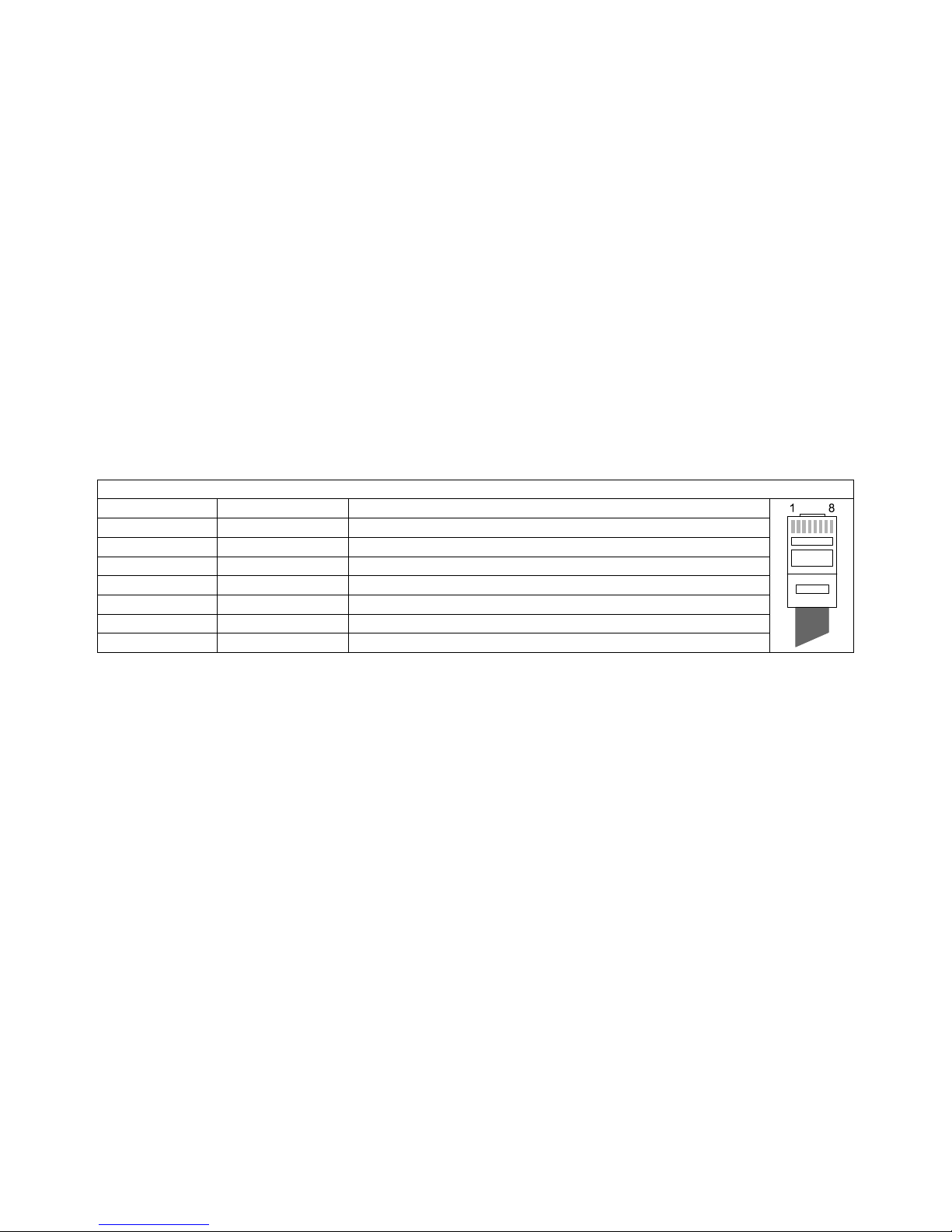
And for XLR connector:
Hot or direct signal > Pin 2
Cold or inverted signal > Pin 3
Ground > Pin 1
Microphones should have a low impedance (200 to 600Ω) and be monophonic. For UNBALANCED connections,
you must short pin 3 (negative) to ground.
For inputs with a MIC/LINE selection, suitable operating position should be set with the dedicated back panel
switch: Engaged: line signal
Released: microphone signal
NOTE: In microphone mode the MIC LEVEL knob located next to the previous switch is enabled.
The gain for each input source (1 to 5) is set with the GAIN rotary knob on the front panel. Please refer to section 6.
CONSIDERATIONS for more information.

5
Stereo LINE inputs accept 0 dBV (1 V) line level signals from CD and DVD players, multimedia devices, MP3
players, radio tuners, TV receivers, etc. Turntables CANNOT BE CONNECTED directly to the MZ54, as none of
the inputs has a built-in RIAA preamplifier.
4.2. Phantom power
An internal jumper activates the Phantom power supply for all microphone inputs at a time, allowing to connect
condenser microphones.
5. OUTPUTS
5.1. Zone outputs
The MZ54 has four main or zone outputs, all balanced and with Euroblock connectors: ZONE 1, ZONE 2, ZONE 3
and ZONE 4.
Euroblock connector should be wired as indicated:
Hot or direct signal > Pin +
Cold or inverted signal > Pin -
Ground > Pin ⊥
5.2. Phones output
In the MONITOR section, the PHONES output allows to monitor any zone output signal, from 1 to 4, as well as the
signal received through the fifth input of the equipment, dedicated to high-priority signals.
6. CONSIDERATIONS AND START-UP
6.1. Power-up
This is done by means of the Power switch (27).
6.2. Input gain
The gain is controlled with knob (4) for each input.
The SP indicator (2) lights to indicate a signal presence in this input.
The CLIP indicator (3) warns that the channel is nearly overloaded. This indicator should never stay permanently
lit.
On the front panel, Input # 5 has a GAIN knob acting as a general control of this signal send to zone outputs in Priority
mode (see 4.2. Input 5, priority). Additionally, inside the unit, 4 adjustment potentiometers allow to attenuate the
individual signal sent from Input 5 to the 4 output zones, customising this input sound volume for the different zones in
Priority mode.
6.3. Destination selection for Input #5
Next to the INPUT 5 gain knob on the front panel, use the ZONE 4 ways switch to define the destination zones for
this input in Priority mode (see section 4.2. Input 5, priority). An output zone (from 1 to 4) is selected as Input #5
destination when its switch is activated (downwards).
If you want to work in Priority mode with activation by external contact closure, connect this external contact to PRIO
terminals on the back panel.
NOTE: Remember that with the other input #5 operating mode (Evacuation/Emergency), the ZONE selector for
destination zones is deactivated, since this mode always mutes the current program signal in All zones outputs,
replacing it with Input #5 signal.

6
6.4. Equalization
Tone controls (7-8) provide a gain/attenuation of ±15 dB for each one of the LOW and TREBLE bands.
6.5. Output volume adjustments
Output volume can be adjusted for each zone by two controls:
The VOL rotary knob on the front panel when the associated REM/LOC switch is in Local position (released)
The Volume rotary knob on the remote wall panel (if installed) when the associated REM/LOC switch is in
Remote position (engaged)
The active source can be selected for each zone by two controls:
The SOURCE rotary selector on the front panel to select one equipment input (1 to 4) or none (OFF)
The INPUT rotary selector on the wall remote panel (if installed) when the front panel associated rotary
selector (SOURCE) is on Remote position. Available options are also input sources 1 to 4, or none (OFF)
6.6. Wall remote control connection
The wall remote controls are connected to the MZ54 by means of a standard CAT5 cable terminated on both ends
with RJ-45 connectors: insert one of them in a REMOTE port on the back panel (ZONE 1, ZONE 2, ZONE 3 or
ZONE 4) and the other in the RJ-45 port of the remote control.
RJ-45 connector wiring
Pin 1 to Pin 1
White/Orange
GND
Pin 2 to Pin 2
Orange
REMOTE VOL (10V÷0V MIN÷MAX)
Pin 3 to Pin 3
White/Green
GND
Pin 4 to Pin 4
Blue
N.C.
Pin 5 to Pin 5
White/Blue
N.C.
Pin 6 to Pin 6
Green
VCC (+10V)
Pin 7 to Pin 7
White/Brown
GND
Pin 8 to Pin 8
Brown
REMOTE ZONE (0, 3, 5, 7, 10V OFF, Z1, Z2, Z3, Z4)
6.7. Audio monitoring system
Use the MONITOR section to monitor the sound volume and content for output zones and Input #5, as described in
section 5.2. Phones output.
6.8. Security cover
To remove the security cover, remove the two small cross head screws on the left and right of the cover. This will
give you access to the Zone selector for input 5, the high and low adjustment for the outputs and the local and
remote controls for all outputs.

7
7. FUNCTION LIST
MZ54 Main Unit
1. Space reserved for writing
2. Visual indication, SP
3. Visual indication, CLIP
4. Channel volume control
5. Destination zone selector, ZONE
6. Local/Remote selector, LOC / REM
7. Low control, LOW
8. Treble control, TREBLE
9. Volume control OUTPUT, VOL ZONE
10. Input selector, SOURCE
11. POWER indicator
12. Phones source selector, ZONE
13. Volume control for headphones output, MONITOR
14. Headphones connector
15. Input sensitivity adjustment, MIC LEVEL
16. Input selector, MIC / LINE
17. Signal input XLR3 connector
18. Signal input screw terminal, LINE R
19. Signal input screw terminal, MIC / LINE L
20. Signal input screw terminal, LINE L
21. Volume control, LEVEL
22. Screw terminal, FIRE LINK
23. Output screw terminal, OUTPUT ZONE
24. RJ-45 connector, REMOTE ZONE
25. Ground terminal, GND
26. Power switch
27. Fuse holder
28. Mains socket
MZR1 Remote
1. Remote volume control
MZR2 Remote
1. Remote volume control
2. Remote source control

8
8. FUNCTION DIAGRAM

9
10. TECHNICAL CHARACTERISTICS
Inputs Sensitivity nom(*)/Impedance MIC BAL -50(-20)dBV/>2kΩ
LINE (1-2-5) -10dBV/2kΩ
LINE (3-4) -10dBV/50kΩ
OutputsLevel/Minimum load OUTPUT BAL 0(+6)dBV/600Ω1(2)V
HEADPHONES200mW/200ΩTHD 1%
Remote Analog Control
Frequency response LINE 5Hz-40kHz -3dB
MIC BAL 5Hz-37kHz -3dB
Harmonic distortion LINE <0.08%
MIC BAL <0.1%
CMRR MIC >70dB@1kHz
Signal/Noise ratio LINE >110dB
MIC BAL >100dB
Tone control BASS 100Hz ±15dB
TREBLE 10kHz ±15dB
Talkover TIME 1 / 2 / 3 sec
EFFECT -20 /-30 / -80 dB
Phantom voltage +18VDC
Mains 90-264VCA 47-63Hz
Power consumption 29VA
Dimensions Panel 482.6x44mm
Depth 195mm
Weight 2.7kg
(*) Internally selectable

10
10. BLOCK DIAGRAM
Table of contents