5
XENYX 1204/1204FX
1.1 General mixing console functions
A mixing console fulfils three main functions:
sSignal pr cessing: Preamplification, level adjustment,
mixing of effects, frequency equalization.
sSignal distributi n: Summing of signals to the aux sends
for effects processing and monitor mix, distribution to one
or several recording tracks, power amp(s), control room
and 2-track outputs.
sMix: Setting the volume level, frequency distribution and
positioning of the individual signals in the stereo field, level
control of the total mix to match the recording devices/
crossover/power amplifier(s). All other mixer functions can
be included in this main function.
The interface of BEHRINGER mixing consoles is optimized for
these tasks enabling you to easily keep track of the signal path.
1.2 The users manual
The users manual is designed to give you both an overview of
the controls, as well as detailed information on how to use them.
In order to help you understand the links between the controls,
we have arranged them in groups according to their function. If
you need to know more about specific issues, please visit our
website at http://www.behringer.com, where youll find
explanations of e.g. effects and dynamics applications.
+The bl ck diagram supplied with the mixing c ns le
gives y u an verview f the c nnecti ns between
the inputs and utputs, as well as the ass ciated
switches and c ntr ls.
For the moment, just try and trace the signal path from the
microphone input to the aux send 1 connector. Dont be put off
by the huge range of possibilities its easier than you think! If you
look at the overview of the controls at the same time, youll be
able to quickly familiarize yourself with your mixing console and
youll soon be making the most of all its many possibilities.
1.3 Before you get started
1.3.1 Shipment
Your mixing console was carefully packed in the factory to
guarantee safe transport. Nevertheless, we recommend that
you carefully examine the packaging and its contents for any
signs of physical damage, which may have occurred during
transit.
+If the unit is damaged, please d NOT return it t us,
but n tify y ur dealer and the shipping c mpany
immediately, therwise claims f r damage r
replacement may n t be granted.
1.3.2 Initial operation
Be sure that there is enough space around the unit for cooling
purposes and to avoid over-heating please do not place your
mixing console on high-temperature devices such as radiators
or power amps. The console is connected to the mains via the
supplied cable. The console meets the required safety standards.
Blown fuses must only be replaced by fuses of the same type
and rating.
+Please n te that all units must be pr perly
gr unded. F r y ur wn safety, y u sh uld never
rem ve any gr und c nnect rs fr m electrical
devices r p wer cables, r render them in-
perative.
+Please ensure that nly qualified pe ple install and
perate the mixing c ns le. During installati n and
perati n, the user must have sufficient electrical
c ntact t earth, therwise electr static discharges
might affect the perati n f the unit.
1.3.3 Online registration
Please do remember to register your new BEHRINGER
equipment right after your purchase by visiting
www.behringer.com (alternatively www.behringer.de) and
kindly read the terms and conditions of our warranty carefully.
Should your BEHRINGER product malfunction, our goal is to
have it repaired as quickly as possible. To arrange for warranty
service, please contact the retailer from whom the equipment
was purchased. Should your BEHRINGER dealer not be located
in your vicinity, you may directly contact one of our subsidiaries.
Corresponding contact information is included in the original
equipment packaging (Global Contact Information/European
Contact Information). Should your country not be listed, please
contact the distributor nearest you. A list of distributors can be
found in the support area of our website (www.behringer.com).
Registering your purchase and equipment with us helps us
process your repair claims quicker and more efficiently.
Thank you for your cooperation!
2. CONTROL ELEMENTS AND
CONNECTORS
This chapter describes the various control elements of your
mixing console. All controls, switches and connectors will be
discussed in detail.
2.1 Mono channels
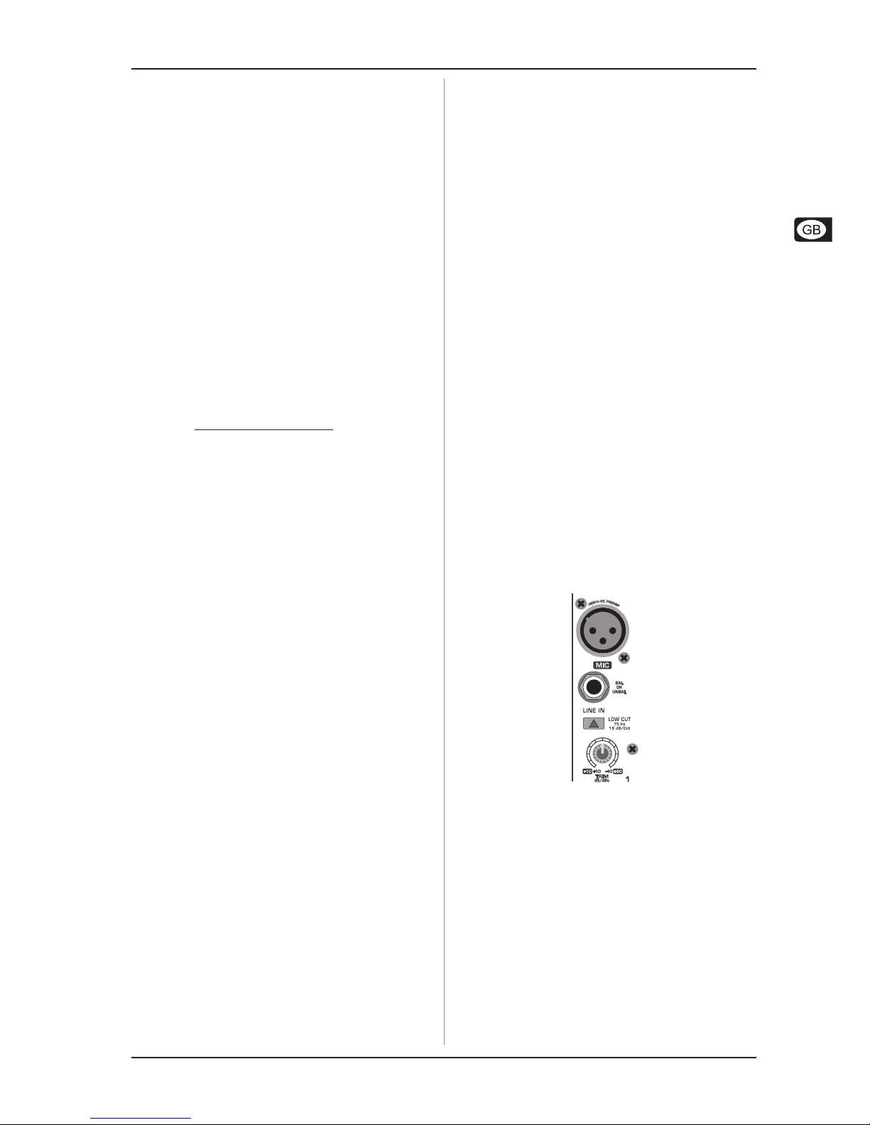
2.1.1 Microphone and line inputs
Fig. 2.1: Connectors and controls of mic/line inputs
MIC
Each mono input channel offers a balanced microphone input
via the XLR connector and also features switchable +48 V
phantom power supply for condenser microphones. The XENYX
preamps provide undistorted and noise-free gain as is typically
known only from costly outboard preamps.
+Please mute y ur playback system bef re y u
activate the phant m p wer supply t prevent
switch- n thumps being directed t y ur l ud-
speakers. Please als n te the instructi ns in
chapter 2.4.2 V ltage supply, phant m p wer and
fuse.
LINE IN
Each mono input also features a balanced line input on a 1/4"
connector. Unbalanced devices (mono jacks) can also be
connected to these inputs.
2. CONTROL ELEMENT AND CONNECTOR