SERIES 569 SELF PROPELLED
3
2.10. When installing the new belt be sure that the belt
is riding within the belt keepers.
See Figure 2.10.
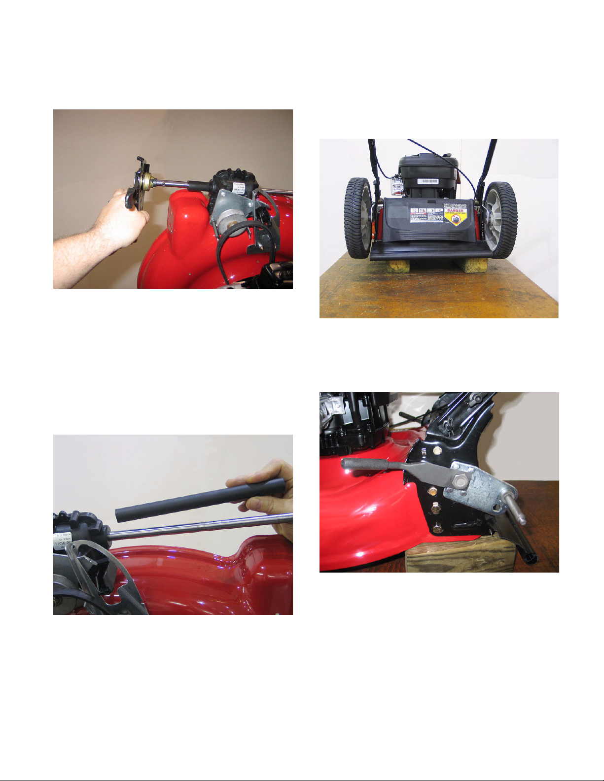
3. BLADE REMOVAL
3.1. Disconnect and ground the spark plug wire.
3.2. Drain the fuel tank or place a piece of plastic
under the fuel cap to prevent gas from leaking.
3.3. Tip the mower on its side so the air cleaner is up.
3.4. Secure the blade from rotating with a block of
wood or a blade lock.
See Figure 3.4.
NOTE: Torque for crack shaft bolt is 450-600
inch pounds
Figure 2.10
Belt Keepers
Figure 3.4
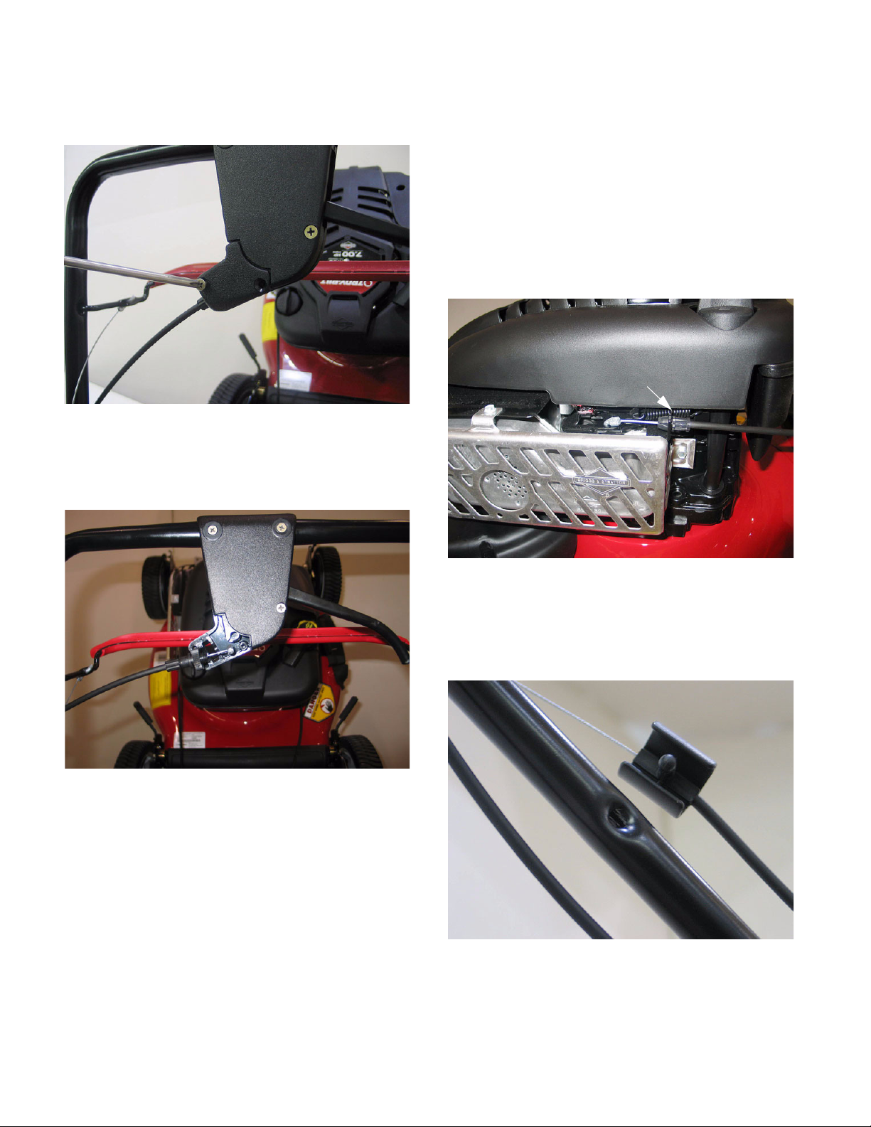
4. TRACTION CONTROL CABLE REMOVAL
4.1. Disconnect and ground the spark plug wire.
4.2. Remove the belt cover.
4.3. Disconnect the Z-fitting from the cable to the sta-
tionary bracket. See Figure 4.3.
NOTE: Slight back pressure will give the cable
slack to disconnect the Z- fitting easily.
NOTE: The cable end is barbed, and fits into a
snap-in cable mount to hold the cable in place.
NOTE: A Ford fuel-line disconnect tool is handy
for releasing barbed cable ends.
4.4. Squeeze the tabs together to allow the cable to
slip through the bracket.
4.5. Cut the cable ties to remove them from the han-
dle. Replace them with new ones during installa-
tion.
4.6. Loosen the wing nuts that secure the upper han-
dle to the lower handle, and carefully fold the
upper handle upward for easy access to the bot-
tom of the self-propel control housing.
NOTE: Use caution not to kink the control
cables.
Figure 4.3