MTD Yard Machines 707 User manual

OWNER’S GUIDE
IMPORTANT: READ SAFETY RULES AND INSTRUCTIONS CAREFULLY
MTD PRODUCTS INC. P.O. BOX 368022 CLEVELAND, OHIO 44136-9722
PRINTED IN U.S.A.
This symbol on the product’s nameplate
UNDERWRITERS LABORATORIES INC.
means it is listed by
UL
®
Form No. 770-8830A
18” Side Discharge
ELECTRIC
LAWN MOWER
Model No. 707
1/98

2
SECTION 1: SAFE OPERATION PRACTICES
This symbol points out important safety instructions which, if not followed, could endanger the
personal safety and/or property of yourself and others. Read and follow all instructions in this manual
before attempting to operate your electric lawn mower. Failure to comply with these instructions may
result in personal injury. When you see this symbol—heed its warning.
DANGER: Your electric lawn mower was built to be operated according to the rules for safe
operation in this manual. As with any type of power equipment, carelessness or error on the part of the
operator can result in serious injury. If you violate any of these rules, you may cause serious injury to
yourself or others.
WARNING: When using electric lawn mowers, basic safety precautions should always be followed
to reduce the risk of fire, electric shock, and personal injury. These basic precautions include the
following:
1. TRAINING
•Read all instructions carefully in their entirety before
attempting to assemble or operate this machine. Be
completely familiar with the controls and the proper
use of this machine before operating it. Keep this
manual in a safe place for future and regular
reference and for ordering replacement parts.
•Your rotary mower is a precision piece of power
equipment, not a plaything. Therefore, exercise
extreme caution at all times.
•Use Right mower—Do not use lawn mower for any
job except that for which it is intended.
•Never allow children to operate a power mower. Only
persons well acquainted with these rules of safe
operation should be allowed to use your mower.
•No one should operate this unit while intoxicated or
while taking medication that impairs the senses or
reactions.
•Stay Alert—Watch what you are doing. Use common
sense. Do not operate lawn mower when you are
tired.
•Keep the area of operation clear of all persons,
particularly small children and pets. Stop motor when
they are in the vicinity of your mower. Although the
area of operation should be completely cleared of
foreign objects, an object may have been overlooked
and could be accidentally thrown by the mower in
any direction and cause serious personal injury to the
operator or any others allowed in the area.
2. PREPARATION
•Prior to each mowing, thoroughly inspect the area
where the equipment is to be used. Remove all
stones, sticks, wire, bones and other foreign objects
which could be picked up and thrown by the mower
in any direction and cause serious personal injury to
the operator or any others allowed in the area.
•Always wear safety glasses or eye shields during
operation or while performing an adjustment or
repair, to protect eyes from foreign objects that may
be thrown from the machine in any direction. Always
use face or dust mask if operation is dusty.
•Dress properly. Wear sturdy, rough-soled work
shoes. Never operate a unit in barefoot, sandals or
sneakers. Do not wear loose clothing or jewelry.
They can be caught in moving parts. Use of rubber
gloves and footwear is recommended when working
outdoors.
•Never attempt to make a wheel or cutting height
adjustment while the motor is running.
•Mow only in daylight or in good artificial light.
•Avoid Dangerous Environment—Never operate the
equipment in the rain or in damp wet locations.
Always be sure of your footing. A slip and fall can
cause serious personal injury. Keep a firm hold on
the handle and walk, never run. Do not over-reach—
keep footing and balance at all times.
•To prevent electric shock, use electric mower only
with a UL Listed extension cord set suitable for
outdoor use, such as Type SW-A, SOW-A, STW-A,
STOW-A, SJW-A, SJOW-A, SJTW-A, or SJTOW-A.
•Extension Cord—Make sure your extension cord set
is in good condition, is heavy enough to carry the
current your mower will draw, and is polarized (one
blade of plug is wider than the other). A 100' length
of 14 AWG extension cord should be used. An
acceptable substitute is a 50' length of 16 AWG cord.
In applications where a longer cord is needed, a 150'
length of 12 AWG cord may be used. An undersized
cord will cause a drop in line voltage resulting in loss
of power and overheating. To reduce the likelihood of
disconnection of the extension cord set from the lawn
mower, be sure to use the cord restraint provided or
make a knot as shown in the illustration below
•To reduce the risk of electric shock, this lawn mower
has a polarized plug (one blade is wider than the
other) and will require the use of a polarized
extension cord. The mower plug will fit into a
Mower
Extension
Cord Cord
Connect Plug and Receptacle

3
polarized extension cord only one way. If the plug
does not fit fully into the extension cord, reverse the
plug. If the plug still does not fit, obtain a correct
polarized extension cord. A polarized extension cord
will require the use of a polarized wall outlet. This
plug will fit into the polarized wall outlet only one
way.If the plug still does not fit into the wall outlet,
reverse the plug. If the plug still does not fit, contact
a qualified electrician to install the proper wall outlet.
Do not change the equipment plug, extension cord
receptacle, or extension cord in any way.
•Inspect lawn mower cord periodically and if
damaged, have it repaired by an authorized service
facility. Keep handles dry, clean, and free from oil
and grease. Inspect extension cord periodically and
replace if damaged.
•Fuses—The mower should be operated on a 15 or
20 AMP circuit. If you experience difficulty in starting
with a standard 15 AMP fuse or circuit breaker,
contact your nearest authorized service location. Do
not use a higher rated fuse without consulting your
power company.
•Ground Fault Circuit Interrupter (GFCI) protection
should be provided on the circuit(s) or outlet(s) to be
used for the lawn mower. Receptacles are available
having built-in GFCI protection and may be used for
this measure of safety.
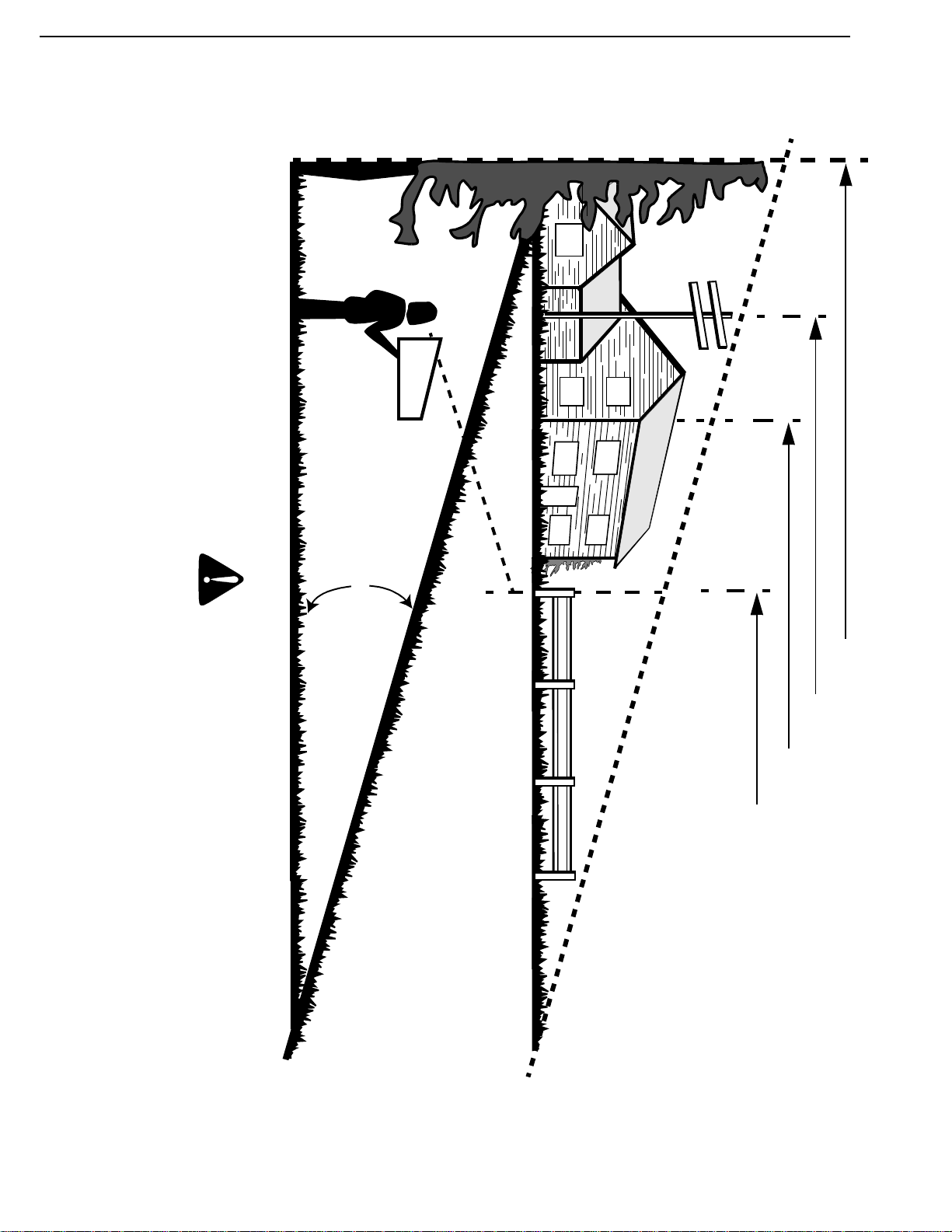
•For your safety, use the slope gauge included as part
of this manual to measure slopes before operating
this unit on a sloped or hilly area. If the slope is
greater than 15° as shown on the slope gauge, do
not operate this unit on that area or serious injury
could result.
3. OPERATION
•Do not abuse cord—never pull lawn mower by cord
or yank it to disconnect from receptacle. Keep cord
from heat, oil, and sharp edges.
•If extension cord is damaged in any manner while
plugged in, disconnect extension cord from house
receptacle.
•Do not put hands or feet near or under rotating parts.
Keep clear of the discharge opening at all times as
the rotating blade can cause injury.
•Stop the motor when you leave the mower and
before crossing gravel drives, walks or roads.
•After striking a foreign object, shut off the motor,
make absolutely sure the blade and all moving parts
have completely stopped, disconnect the power cord
to prevent accidental starting, then thoroughly
inspect the mower for any damage. Such damage
must be repaired before restarting and operating the
mower.
•If the equipment should start to vibrate abnormally,
stop the motor and check immediately for the cause.
Vibration is generally a warning of trouble.
•Stop the motor, unplug the power cord, and wait for
the blade and all moving parts to stop before
cleaning or unclogging, repairing or inspecting the
mower. The cutting blade continues to rotate for a
few seconds after the motor is shut off.
•Do not force lawn mower. It will do the job better and
safer at the rate for which it was designed.
•Mow across the face of slopes, never up-and-down.
Never cut grass by pulling mower toward you.
Exercise extreme caution when operating mower on
uneven terrain or changing direction on slopes. Do
not mow excessively steep slopes. Don’t overreach—
Keep proper footing and balance at all times. A slip
and fall can cause serious personal injury.
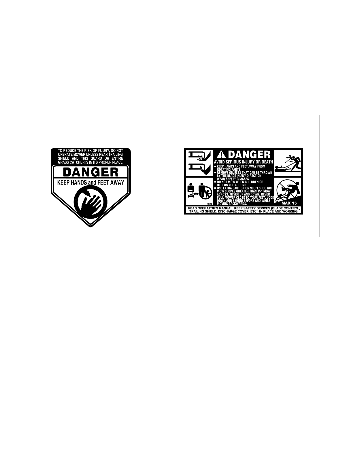
•Never operate mower without proper guards, and
other safety protective devices in place and in
working order.
•The blade/motor control on this mower is installed to
minimize the risk of blade contact injury and is
required by federal regulations. Do not under any
circumstances attempt to defeat the function of the
blade/motor control.
•To avoid electric shock hazard, never push mower
over cord. Do not mow around the lawn in circles.
Always travel back and forth across the lawn,
beginning at the point nearest the electric outlet to
which the extension cord is connected. This will keep
the cord on the mowed area of the lawn and out of
the way.
•Do not operate mower after it has been dropped or
damaged in any manner. Return mower to nearest
authorized service location.
•The use of accessory attachments not recommended
by the mower manufacturer may cause hazards.
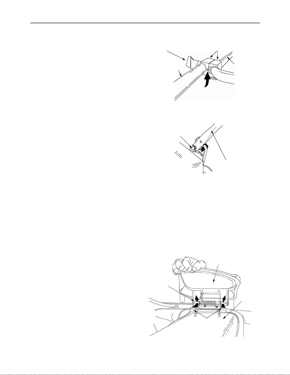
•Do not operate this mower with the chute door open,
unless the complete grass catcher or side chute
deflector is properly mounted on the mower.
4. MAINTENANCE AND STORAGE
Warning: Disconnect lawn mower from
electrical outlet when not in use, before
performing any maintenance or service on
mower and when changing accessories
such as blades and the like.
•Check the blade and motor mounting bolts at
frequent intervals for proper tightness. Keep all nuts,
bolts, and screws tight to be sure the equipment is in
safe working condition.
•Keep blade sharp.
•Use identical replacement blades only. Replace
damaged cord.
•To reduce fire hazard, keep the motor free of grass,
leaves, or excessive grease.
•Store idle lawn mower indoors when not in use.
Allow motor to cool before storing in any enclosure.
Lawn mower should be stored indoors in dry, high or
locked-up place, out of reach of children.

4
•Maintain lawn mower with care. Keep blade sharp
and clean for best and safest performance. Follow
instructions for lubricating and changing
accessories.
•Check the grass catcher bag frequently for wear or
deterioration. Replace a worn or damaged bag
immediately. Be sure replacement bag meets
original equipment specifications.
5. DOUBLE INSULATED LAWN MOWER
Double insulation is a concept in safety in electric lawn
mowers, which eliminates the need for the usual three-wire
grounded power cord and grounded supply system.
Wherever there is electric current in the mower, there are
two complete sets of insulation to protect the user. All
exposed metal parts are isolated from the internal metal
motor components with protecting insulation.
IMPORTANT: Servicing of a lawn mower with double
insulation requires extreme care and knowledge of the
system and should be performed only by a qualified service
technician. For repair service we suggest you return the
lawn mower to your nearest authorized service dealer.
Always use original factory replacement parts when
servicing.
Figure 1
You will find the two safety labels reproduced below, on your mower. Please follow
instructions on these safety labels for safe operation of the mower.

5
SECTION 2: FINDING YOUR MODEL NUMBER
This Operator’s Manual is an important part of your new walk behind. It will help you assemble, prepare and
maintain your walk behind. Please read and understand what it says.
Before you start to prepare your walk behind for its first use, please locate the model plate and copy the
information from it in this Operator’s Manual. The information on the model plate is very important if you need
help from your dealer or the MTD customer support department.
•Every walk behind has a model plate. You can locate it by standing behind the unit in the operating
position and looking down at the rear of the deck.
•The model plate will look like Figure 2.
Figure 2
SECTION 3: CALLING CUSTOMER SUPPORT
If you are having difficulty assembling this product or if you have any question regarding the controls,
operation or maintenance of this unit, please call the Customer Support Department. You can reach them by
calling:
1-800-800-7310
Before you call, make sure that you have your model and serial numbers ready. By having the model and
serial numbers ready, you help the Customer Support Representative give you faster service. To find your
unit’s model and serial number, see SECTION 2: FINDING YOUR MODEL NUMBER.
MTD PRODUCTS INC
CLEVELAND, OHIO 44136
XXX-X-XXX-X-XXX XXXXXXXXXXX
This is where your model number will be.
This is where your serial number will be.
Copy the model number here:
Copy the serial number here:

6
SECTION 4: SLOPE GAUGE
15°
SIGHT AND HOLD THIS LEVEL WITH A VERTICAL TREE
A POWER POLE
A CORNER OF A BUILDING
OR A FENCE POST
FOLDONDOTTEDLINE,REPRESENTINGA15°SLOPE
USE THIS PAGE AS A GUIDE TO DETERMINE SLOPES WHERE YOU MAY NOT OPERATE SAFELY.
Do not mow on inclines with a slope in excess of 15 degrees (a rise of approximately 2-1/2 feet every 10 feet). A riding mower
could overturn and cause serious injury. If operating a walk-behind mower on such a slope, it is extremely difficult to maintain
your footing and you could slip, resulting in serious injury.
Operate RIDING mowers up and down slopes, never across the face of slopes.
Operate WALK-BEHIND mowers across the face of slopes, never up and down slopes.
WARNING

7
SECTION 5: ASSEMBLY
NOTE: Reference to right or left hand side of the
mower is observed from the operating position.
You will have to use an extension cord,
purchased separately, to run this unit. Please
refer to page 10 for appropriate cord selection.
REMOVING UNIT FROM CARTON
1. Remove staples, break glue on top flaps, or cut
tape at carton end and peel along top flap to
open carton.
2. Remove loose parts if included with unit (i.e.,
owner’s manual, etc.).
3. Cut along dotted lines and lay carton down flat.
4. Remove packing material.
5. Roll or slide unit out of carton. Check carton
thoroughly for loose parts.
TOOLS REQUIRED
A pair of pliers
ASSEMBLING HANDLE
1. Remove any packing material which may be
between the upper and lower handles for
shipping purposes.
2. Pull up and back on the upper handle to raise
the handle into the operating position. Make
certain the lower handle is seated securely into
the handle mounting brackets.
3. The upper handle may be adjusted to three
different height positions. To adjust the handle
at the desired position, align one of the three
marks on the top of the lower handle insulators
with the mark on the upper handle insulators.
See Figure 3.
4. Tighten the hand knobs on each side of the
handle. Make sure that carriage bolts are
seated properly into the handle insulators
5. Remove the hairpin clips from the outer hole in
the weld pins on the handle mounting brackets.
6. Using a pair of pliers, squeeze one leg of the
lower handle against the handle mounting
bracket. Insert the hairpin clip into the inner hole
on the weld pin. Repeat on the other side. See
Figure 4.
7. Make certain all nuts and bolts are tightened
securely.
Figure 3
Figure 4
Converting from Mulching to Side
Discharge
1. To convert your mower from a mulcher to a side
discharge mower, lift the mulching plug. Slide
the two hooks on the side discharge deflector
under the hinge pin on the mulching plug
assembly. Lower the mulching plug. Do not
remove the mulching plug at any time, even
when you are not mulching. See Figure 5.
.
Figure 5
Upper
Handle
Lower Handle
Insulator
Hand
Knob
(Align marks here)
Lower Handle
clip here
Mulching Plug
Hinge Pin
Side
Discharge
Deflector
Hook
(Slide hooks under the two
sides of hinge pin)

8
SECTION 6: OPERATION
KNOW YOUR LAWN MOWER
READ THIS OWNER’S MANUAL AND SAFETY
RULES BEFORE OPERATING YOUR LAWN
MOWER. Compare the illustrations with your lawn
mower to familiarize yourself with the location of
various controls and adjustments. Save this manual
for future reference.
MEETS CPSC SAFETY REQUIREMENTS
Your rotary walk-behind power lawn mower
conforms to the safety standards of the American
National Standards Institute and the U.S. Consumer
Product Safety Commission. The blade turns when
the motor is running.
Figure 6
Motor/Blade Control Assembly
WARNING: :Federal regulations require
a motor/blade control to be installed on
lawn mower in order to minimize the risk of
blade contact injury. DO NOT under any
circumstances attempt to defeat the
function of the motor/blade control. Never
attempt to bypass its operations.
NOTE: Your lawn mower is equipped with a motor/
blade control which requires the operator to be
positioned behind the lawn mower handle to start
and operate the lawn mower.
The motor/blade control is located on the upper
handle of the mower. See Figure 6. The motor/
blade control engages and disengages the motor
and blade.
Circuit Breaker
Your mower is equipped with a circuit breaker,
located near under the motor/blade control
assembly. This circuit breaker may trip when too
much stain is placed on the mower.
Starter Control Lever
The starter control lever is located on the motor/
blade control assembly. Standing behind the unit,
press the upper control lever with your left hand and
squeeze the lever with your right hand against the
upper handle. The motor will start.
Stopping the mower
Release the starter control lever to stop the
motor and the blade.
Side
Discharge
Deflector
Motor/Blade
Control Assembly
Motor
Cord
Restraint
Hand
Knob
Hand Knob Height
Lever
Adjustment
Upper Handle
Lower Handle
Mulching
Plug
Insulator
Height
Lever
Adjustment

9
WARNING: :The operation of any lawn
mower can result in foreign objects being
thrown into the eyes, which can result in
severe eye damage. Always wear safety
glasses or eye shields.
NOTE: : The wheels on your unit are set in a low
cutting height position for shipping purposes. For
best results, raise the cutting position until it is
determined which height is best for your lawn. See
cutting height adjustment.
CORD CONNECTION
Cord Selection
IMPORTANT: A 100 feet length of 14 AWG
extension cord should be used. An acceptable
substitute is a 50 feet length of 16 AWG cord. In
applications where a longer cord is needed, a 150 -
feet long 12 AWG cord may be used. Using any
other length or rating of cord will diminish the
performance and possibly the life of the electric
motor. In all cases, the extension cord should be a
UL listed cord set suitable for outdoor use.
Cord Restraint
1. Attach extension cord (not provided with unit) to
the cord restraint as follows.
2. Form a small loop in the extension cord. Allow
enough excess cord to make the connection to
the motor/blade control (approximately 20
inches).
3. Slip the loop through the slot on the bottom of
the cord restraint, and up over the tab, to
prevent disconnection from the motor/blade
control during operation.
Keep the cord restraint as close to the motor/blade
control as possible. See Figure 7
Figure 7
Connection to the Blade Control Assembly
•Connect the plug on the extension cord fully
onto the plug on the mower. The mower is
equipped with a polarized AC power plug
(one blade of the plug is wider than the
other), which will fit into the plug on the
extension cord only one way. If unable to
make a full connection, try reversing the plug
on the extension cord. Should the plugs still
fail to fit, contact your service dealer for
assistance. Do not defeat the safety purpose
of the polarized plug.
Connection to the Electric Power Source
•Plug the extension cord into any convenient
110-120 volt 60 cycle A.C. outlet or
receptacle for your source of power. This
outlet may be located either out-of-doors or
indoors. To avoid blowing fuses, pick an
outlet that is not overloaded. Your mower will
operate satisfactorily on a circuit that is fused
for 15 amperes. Do not use oversize fuses
without consulting your power company. If an
inside receptacle is used, the extension cord
can be taken out either through the doorway
or a window.
TO START MOTOR AND BLADE
1. Standing behind the unit, depress the upper
starter control lever with your left hand and
squeeze the lever with your right hand against
the upper handle. The motor will start. See
Figure 8.
Motor/Blade
Control
Assembly
Circuit Breaker
Reset Button
Cord
Restraint

10
Figure 8
IMPORTANT: : Your mower is equipped with a
circuit breaker, located under the blade control
assembly. See Figure 7. If the circuit breaker trips,
reset as instructed in the Maintenance section.
TO STOP MOTOR AND BLADE
1. Release the starter control lever to stop the
motor and blade. A high pitched noise will
result, due to deceleration of the electric motor.
Sparking at the top of motor is also normal
during deceleration.
WARNING: The blade continues to
rotate for a few seconds after the
motor is shut off. If motor does not
come to an immediate stop when the
motor/blade control handle is released,
contact an authorized service dealer.
2. Disconnect the power source to prevent
accidental starting while equipment is
unattended.
USING YOUR ROTARY MOWER
WARNING: Do not operate this
mower with the chute door open,
unless the complete grass catcher is
properly mounted on the mower.
1. Be sure that lawn is clear of stones, sticks,
wires, or other objects which could damage
lawn mower or motor. Such objects could be
accidentally thrown by the mower in any
direction and cause serious personal injury to
the operator and others.
2. To prevent electric shock, do not operate the
mower in damp or wet locations.
Mowing Pattern:
1. Always start from the point closest to the
power source where the cord is connected.
Never mow around the lawn in circles; travel
back and forth across the lawn, starting from the
point closest to the outlet and then moving away
from the outlet so the cord lies in the cut portion
of the lawn, out of the way. See Figure 9.
Figure 9
2. Do not allow extension cord to wrap around
trees, shrubs or other obstacles. When picking
up the extension cord, wind the cord in a series
of equal loops on each side of your hand to
prevent snarling.
3. When cutting heavy grass, reduce walking
speed to allow more effective cut and proper
discharge of the clippings. For a healthy lawn,
always cut off one-third or less of the total
length of the grass. The average lawn should be
approximately 1-1/2 to 2 inches during the cool
season, and over 2 inches during hot months.
For a healthier and better looking lawn, cut
more often and after moderate growth. The
lawn should be cut in the fall as long as there is
growth.
A
B T = Obstacles
Outlet
(Start here)

11
Tips for mulching:
•For effective mulching, do not cut wet grass
because it tends to stick to the underside of
the deck, preventing proper mulching of grass
clippings. New or thick grass may require a
narrower cut. The ground speed should be
adjusted to the condition of the lawn. If
mowing has been delayed and the grass has
been allowed to grow in excess of 4", mow
twice to reduce the grass height to 3-1/4"
maximum.
WARNING: :If you strike a foreign
object, stop the motor. Disconnect the
power source, thoroughly inspect the
mower for any damage, and repair the
damage before restarting . Extensive
vibration of the mower during operation
is an indication of damage. The unit
should be promptly inspected and
repaired.
SECTION 7: MAINTENANCE
GENERAL RECOMMENDATIONS
1. Always observe safety rules when performing
any maintenance.
2. The warranty on this electric mower does not
cover items that have been subjected to
operator abuse or negligence. To receive full
value from the warranty , operator must
maintain the mower as instructed in this manual.
3. Some adjustments will need to be made
periodically to maintain your unit properly.
4. All adjustments in the Service & Adjustments
section of this manual should be checked at
least once each season.
WARNING: Always stop motor and
disconnect the power source before
cleaning, lubricating or performing any
repairs or maintenance on lawn mower.
CUTTING BLADE
WARNING: Always protect hands by
wearing heavy gloves and/or wrapping
cutting edges with newspapers or other
materials when performing any blade
maintenance. Be certain to disconnect
the power supply.
Removing Blade
1. Stop the motor and disconnect the power
supply to the mower. Turn mower on its side.
2. Use a block of wood between blade and mower
deck to prevent blade from turning when bolt is
removed.
Figure 10
3. Using a 3/8” box or open-end wrench, remove
center bolt and bell washer which hold the fan,
blade and adapter to the motor shaft. See
Figure 10.
4. Remove the fan, blade and adapter from the
shaft.
5. Remove the two small bolts, flat washers and
nuts which hold the blade to the adapter. See
Figure 10. Remove fan from blade adapter.
Replacing Blade
1. Put blade adapter on motor shaft.
2. Fit blade in adapter making sure that the trailing
edge of the blade is up towards the engine, and
the side of the blade marked “Bottom” (or with
part number) faces the ground when the mower
is in the operating position.
3. Before reassembling the blade and the blade
adapter to the unit, lubricate the motor shaft and
the inner surface of the blade adapter with light
oil (or engine oil). Lubricating the bolt holes,
bolts and inner surface of the nuts is also
recommended.
Hex Bolt
Bell Washer
Hex Bolt
Hex Bolt
Flat Washer
Flat Washer
Blade Adapter
Blade
Fan

12
4. Assemble bolts, washers, and nuts in the exact
order of removal. Make sure to assemble the
fan properly before running the mower. See
Figure 10.
WARNING: Periodically inspect the blade
adapter for cracks, especially if you strike
a foreign object. Replace when necessary.
Blade Mounting Torque
The recommended torque for the center blade bolt
is 450-600 in. lbs. The recommended torque for the
two blade adapter bolts is 200-350 in. lbs.
To insure safe operation of your unit, all nuts and
bolts must be checked periodically for correct
tightness.
Sharpening blade
1. The blade can be sharpened with a file or on a
grinding wheel. Do not attempt to sharpen
while on the mower.
2. When sharpening the blade, follow the original
angle of grind as a guide. It is extremely
important that each cutting edge receives an
equal amount of grinding to prevent an
unbalanced blade.
3. Test the blade by balancing it on a round shaft
screwdriver or a blade balancer. Figure 11.
NOTE: An unbalanced blade will cause excessive
vibration when rotating at high speeds, may cause
damage to the mower and could break, causing
personal injury.
4. If the blade is not balanced, remove metal from
the heavy side until it balances evenly. We
recommend that the blade be always removed
from the adapter for the best test of balance
Figure 11
5. When replacing the blade, be sure to install the
blade with the side of the blade marked
“Bottom” (or with part number) facing the
ground when the mower is in the operating
position. Also make sure to follow the correct
order as shown in Figure 10.
DECK
NOTE: The underside of mower deck should be
cleaned after each use as grass clippings, leaves,
dirt and other matter will accumulate. This
accumulation of grass clippings, etc., is undesirable
as it will promote rust and corrosion.
1. Remove any buildup of grass and leaves on or
around the motor cover (do not use water).
Wipe mower clean with a dry cloth occasionally.
2. Disconnect the power source. Tilt the mower
forward or on its side and scrape clean with a
suitable tool.
WARNING: To reduce the risk of electric
shock, do not expose mower to water.
1. Insert screw driver through hole
2. Blade should be parallel to ground
Screw
Driver
Ground
Blade

13
Figure 12
LUBRICATION
Refer to Lubrication Chart.
1. Keep unit well lubricated. Lubricate the bolts
holding the height adjustment lever to the deck
with a light oil. See Figure 12.
2. If the wheels are removed for any reason,
lubricate the surface of the axle and the inner
surface of the wheel with light oil. See Figure 12.
3. If you are reassembling the blade and the blade
adapter to the unit, lubricate the motor shaft and
the inner surface of the blade adapter with light
oil (or engine oil). See Figure 12.
Also lubricate the bolt holes, bolts and inner surface
of the nuts in the blade adapter assembly before
reassembly. See Figure 12.
SECTION 8: SERVICE & ADJUSTMENT
CUTTING HEIGHT ADJUSTMENT
Figure 13
A height adjustment lever at each wheel provides
cutting height adjustment. Each adjuster has nine
height positions. Height of cut will be changed when
the lever is moved from one position to another.
Simply depress the lever towards wheel and move
wheel and lever assembly to desired position. See
Figure 13. All wheels must be placed in the same
relative position. For rough or uneven lawns, move
the wheels to a position which will give a higher
cutting height.
HANDLE HEIGHT ADJUSTMENT
The upper handle may be adjusted to three different
height positions. To select desired position, loosen
hand knobs and align one of the three marks on the
top of the lower handle insulators with the mark on
LUBE
LUBE
Cutting Height
Adjustment Lever

14
the upper handle insulators. Tighten the hand
knobs. Refer to Figure 3.
CIRCUIT BREAKER ADJUSTMENT
The circuit breaker is located under the blade
control assembly. This breaker may trip when too
much strain is placed on the mower. The circuit
breaker has been tripped if the mower will not run,
and the white part of the reset button projects out of
the blade control assembly housing. Refer to Figure
7.
1. If this occurs, wait approximately 30 seconds,
then depress the reset button. Refer to Figure 7.
2. Restart the mower, but be sure to reduce the
strain on the mower (i.e., mow at a higher
cutting height, slow down, or take a smaller
width of cut).
3. If the circuit breaker does not reset, or if it trips
repeatedly under normal cutting conditions, take
the mower to an authorized service dealer.
SECTION 9: OFF-SEASON STORAGE
Your mower should be prepared for off-season or
long storage by following the steps mentioned
below.
MOWER
1. Make certain the power supply is disconnected.
2. Clean mower as instructed in previous section.
3. Inspect and replace/sharpen blade if required.
Refer to Cutting Blade section on page 11.
4. Lubricate mower following instructions in the
lubrication section on page 13.
HANDLE
The handle may be folded away completely for
storage.
1. Loosen the hand knobs on the sides of the
handle, and fold the upper handle down.
2. Pull outward on each side of the lower handle,
and lift the sides of the lower handle past the
edges of the handle mounting brackets. Fold
the lower handle forward. Make sure not to
bend or kink the power cord.
EXTENSION CORD
1. Wipe extension cord to remove any foreign
substance such as oil or stains. Replace
extension cord if cut or damaged in any way.
2. Wind cord in a series of equal loops on each
side of your hand to prevent snarling.
STORAGE
•Store mower indoors, in a cool, dry place, out
of reach of children. Do not cover lawn
mower with a solid plastic sheet. Any plastic
covering traps moisture around the mower
which promote rust and corrosion.

15
SECTION 10: TROUBLE-SHOOTING
WARNING: :Before doing any kind of investigative or repair job on the mower, stop the motor
and disconnect from power source. Always protect hands by wearing heavy gloves when
performing any blade maintenance
Trouble Possible Causes Corrective Action
Handle not in position 1. Carriage bolts not seated in the
handle insulators 1. Adjust the height of the handle and
make sure that the carriage bolts
are seated properly into the handle
insulators. Tighten the hand knobs.
Mower not starting 1. Cord disconnected from the motor/
blade control
2. Motor/blade control switch defective.
3. Extension cord not connected to
the plug on the mower.
4. Extension cord not connected to a
source of power.
5. Circuit breaker on the mower or on
the house receptacle tripped
1. Reconnect the cord keeping the
cord restraint close to the motor/
blade control.
2. Replace motor/blade control switch.
3. Connect the extension cord to the
plug on the mower.
4. Connect the extension cord to an
indoor or outdoor 110-120 volt 60
cycle A.C. receptacle.
5. Reset the circuit breaker following
instructions in the Maintenance
section of this manual.
Circuit breaker on the mower tripping 1. Too much work load on the mower
2. Fuse blown; outlet overloaded.
1. Raise the cutting height, reset the
circuitbreakeronthemower, takea
smaller width of cut, and walk
slowly.
2. Connect to an outlet that is fused
for 15 amperes. Reset the circuit
breaker and start the mower again.
Mower cutting grass unevenly 1. Cutting height not set properly.
2. Lawn rough or uneven.
1. All wheels must be placed in the
same cutting height for the mower
to cut evenly.
2. Move the wheels to a higher cutting
height position.
Mower not mulching properly 1. Wet grass clippings stick to the
underside of the deck. 1. Wait till the grass dries before
mowing.
Hard to push 1. High grass or cutting height too low.
2. Rear of mower housing and
blade dragging in heavy grass
1. Raise cutting height
2. Raise cutting height.
Mower vibrating at higher speed 1. Blade is unbalanced.
2. Bend motor shaft.
1. Balance the blade by grinding each
cutting edge equally.
2. Stop the motor, disconnect the
power source and inspect for
damage. Repair before restarting. If
vibrationpersists,takeittoaservice
dealer.

16
Model 707
55

17
Model 707
REF.
NO. PART NO. DESCRIPTION
1749-0886 Upper Handle
2747-0790 Cord Control Rod
3725-1590 Strain Relief Cord
4731-1270 Fan
5748-0356 Blade Adapter
6738-0102 Axle Bolt
717098 Hinge Clip
8731-1028 Rear Flap
9749-0885 Lower Handle
13 714-0104 Hairpin Clip
15 738-0507B Shld. Bolt .5" Dia. x .434"
20 682-3024 Handle Brkt. Assy.—R.H.
21 682-3025 Handle Brkt. Assy.—L.H.
24 736-0105 Spr. Washer .401 x .870 x .063
25 736-0356 Bell Washer .39" I.D. x 1.38" O.D.
26 712-0798 Hex Nut 3/8-16 Thd.*
27 14832 Spring Lever Assy. w/Knob
28 15262B Pivot Bar
29 15261A Height Adj. Plate
31 682-0018 18" Deck Assy.
32 14578 Height Adj. Assy. Comp.—R.H.
14579 Height Adj. Assy. Comp.—L.H. (Not Shown)
33 731-1263 Motor Cover
34 710-3009 Screw #10-24 x .75" Lg.
35 710-0605 Oval C-Sunk Screw 1/4-20 x 1.81
36 712-0241 Lock Nut 3/8-24 Thd.
37 710-0654A Hex Lock Wash. TT-Tap Scr. 3/8-16 x1.00"
38 710-0191 Hx Hd.3/8-24: 1.25 Lg.
39 736-0452 Bell Washer .396" I.D. x 1.14"
41 720-0241 Plastic Knob
42 734-1781 Wheel Assy. Comp. (8" x 1.75")
734-1699 Wheel Assy. Comp. (7" x 1.5")
43 731-1268 Upper Handle Insulator
44 731-1267 Lower Handle Insulator
45 710-0450 Carriage Bolt 5/16-18 x 3" Lg.
46 720-0279 Wing Nut 1/4-20 Thd.
47 726-0240 Cable Tie
48 736-0331 Bell Wash. .39 x 1.13 x .062
49 624-0099 Motor, Cord & Switch Assy.**
50 625-0050 Switch Assembly.
53 742-0718 18" Blade
54 731-1501 Mulching Plug
55 750-0218 Spacer
66 720-0226 Foam Grip (Optional)
70 721-0311 Insulator
71 726-0209 Cable Tie
72 731-1388 Insulator Knob
73 710-1251 Hex Bolt 3/8-24 x 2.5" Lg.
78 720-0258 Hub Cap (Optional)
78 731-1409 Chute Deflector
80 736-0270 Bell-Wash. 1/4" I.D.
81 710-0599 Hex Wash. Hd. TT-Tap Scr.
1/4-20 x .5" Lg.
87 747-0710 Hinge Pin
88 782-7006 Hinged Mounting Bracket
89 732-0731 Torsion Spring
90 --- Handle Bracket Ass’y - (Part of Ref. 20)
REF.
NO. PART NO. DESCRIPTION

18
REF.
NO. PART NO. DESCRIPTION
1710-1150 Scr. Hx. Lock #7-19 X 1.00 Lg.
2712-0189 Nut Weld Tab 1/4-20 Thd.
3724-0248 Cord W/ Plug
4725-1712 Circuit Breaker
5725-1731 Switch
6731-1985 Upper Switch Housing
7731-1986 Lower Switch Housing
8731-1987 Control Lever
9732-0935 Torsion Spring
Model 707
Exploded view of Cord & Switch Assembly (Part No. 625-0050)
1
7
4
2
5
98
3
6
5
6

19
Model 707
REF.
NO. PART NO. DESCRIPTION
1624-0031 Brush & Liner Assembly.
2724-0200 Brush Holder Cap
3624-0070 End Shield Assembly. W/plug
(Includes Ref. 1, 2 & 6)
4721-0305 Insulator Wire (Output)
5710-3009 Hex Tap Scr. #10-16 x .62” Lg.
6741-0875 Needle Bearing
7 † Magnet Housing Assembly
8624-0029 Armature Assembly.
9624-0062 Motor End Plate Assembly.
(Includes Ref. 10 & 11)
10 741-0124 Ball Bearing
11 748-0348 Bearing Adapter
12 710-1176 Carriage Bolt
13 712-0324 Hex L-Nut 1/4-20 Thd.
14 736-3090 Fl. Washer .26” I.D. x .72”
15 721-0306 Housing Insulator
16 782-5016 Brkt. Rectifier/Heat Sink
17 725-1715 Rectifier
18 721-0382 Heat Sink Compound
(not shown)
† Not available for service
Model 707

MANUFACTURER’S LIMITED WARRANTY FOR:
For TWO YEARS from the date of retail purchase
within the United States of America, its possessions
and territories, MTD PRODUCTS INC will, at its
option, repair or replace, for the original purchaser,
free of charge, any part or parts found to be
defective in material or workmanship. This warranty
covers units which have been operated and
maintained in accordance with the operating
instructions furnished with the unit, and which have
not been subject to misuse, abuse, commercial use,
neglect, accident, improper maintenance or
alteration.
Normal wear parts or components thereof are
subject to separate terms as noted below in the “No
Fault Ninety Day Consumer Warranty” clause.
All normal wear part failures will be covered on this
product for a period of 90 days regardless of cause.
After 90 days, but within the two year period, normal
wear parts failures will be covered ONLY IF caused
by defects in material or workmanship of OTHER
component parts. Normal wear parts are defined as
batteries*, belts, blades, blade adapters, grass
bags, rider deck wheels, seats, snow thrower skid
shoes, shave plates and tires.
How to obtain service: Warranty service is
available, with proof of purchase, through your local
authorized service dealer. To locate the dealer in
your area, please check the yellow pages or contact
the Customer Service Department of MTD
PRODUCTS INC, P. O. Box 368022, Cleveland,
Ohio 44136-9722. Phone 1 (800) 800-7310. The
return of a complete unit will not be accepted by the
factory unless prior written permission has been
extended by the Customer Service Department of
MTD PRODUCTS INC.
Transportation charges: Transportation charges
for the movement of any power equipment unit or
attachment are the responsibility of the purchaser.
Units exported out of the United States: MTD
PRODUCTS INC does not extend any warranty for
products sold or exported outside of the United
States of America, its possessions and territories,
except those sold through MTD PRODUCTS INC’s
authorized channels of export distribution.
Other Warranties:
1. The engine or component parts thereof carry
separate warranties from their manufacturers.
Please refer to the applicable manufacturer’s
warranty on these items.
2. *Batteries are covered by a 90-day replacement
warranty.
3. Log splitter pumps, valves and cylinders or
component parts thereof are covered by a one
year warranty.
4. All other warranties, express or implied,
including any implied warranty of
merchantability or fitness for a particular
purpose, are hereby expressly disclaimed in
their entirety.
5. The provisions as set forth in this warranty
provide the sole and exclusive remedy of MTD
PRODUCTS INC’s obligations arising from the
sales of its products. MTD PRODUCTS INC will
not be liable for incidental or consequential loss
or damage.
How state law relates to this warranty: This
limited warranty gives you specific legal rights, and
you may also have other rights which vary from
state to state. Certain disclaimers are not allowed in
some states and therefore they may not apply to
you under all circumstances.
NOTE: This warranty does not cover routine
maintenance items such as lubricants, filters, blade
sharpening and tune-ups, or adjustments such as
brake adjustments, clutch adjustments or deck
adjustments. Nor does this warranty cover normal
deterioration of the exterior finish due to use or
exposure.
Other manuals for Yard Machines 707
2
Table of contents
Other MTD Lawn Mower manuals
Popular Lawn Mower manuals by other brands

Parkside
Parkside PRMA 20-Li A1 Translation of the original instructions

Husqvarna
Husqvarna GX560 Original instructions

McCulloch
McCulloch MC1538ST owner's manual

Grizzly Tools
Grizzly Tools BRM 46-144 A-OHV Translation of the original instructions for use

Craftsman
Craftsman T1000 series Operator's manual

Bertolini
Bertolini BTS 80 Use and maintenance