mundoclima CL23220 User manual

MVD
Installation manual
English
CL23220 to CL23223
Console
www.mundoclima.com

Be sure to be in conformity with the local, national and
international laws and regulations.
Read "PRECAUTIONS" carefully before installation.
The following precautions include important safty items.
Observe them and never forget.
Keep this manual with the owner's manual in a handy place
for future reference.
1. PRECAUTIONS
The safty precautions listed here are divided into two categories. In
either case, important safty information is listed which must be read
carefully.
After completing the installation, make sure that the unit operates
properly during the start-up operation. Please instruct the customer
on how to operate the unit and keep it maintained.Also, inform
customers that they should store this installation manual along with
the owner's manual for future reference.
Be sure only trained and qualified service personnel to
install, repair or service the equipment.
Improper installation, repair, and maintenance may result in
electric shocks, short-circuit, leaks, fire or other damage to
the equipment.
Disconnect the power supply before cleaning and
maintenance.
Failure to observe a warning may result in death.
Failure to observe a caution may result in injury or
damage to the equipment.
Install according to this installation instructions strictly.
If installation is defective, it will cause water leakage,
electrical shock fire.
When installing the unit in a small room, take measures
against to keep refrigerant concentration from exceeding
allowable safety limits in the event of refrigerant leakage.
Contact the place of purchase for more information.
Excessive refrigerant in a closed ambient can lead to oxygen
deficiency.
Use the attached accessories parts and specified parts
for installation.
otherwise, it will cause the set to fall, water leakage,
electrical shock fire.
Install at a strong and firm location which is able to
withstand the set' s weight.
If the strength is not enough or installation is not properly
done, the set will drop to cause injury.
The appliance shall not be installed in the laundry.
Before obtaining access to terminals, all supply circuits
must be disconnected.
The appliance must be positioned so that the plug is
accessible.
The enclosure of the appliance shall be marked by word,
or by symbols, with the direction of the fluid flow.
For electrical work, follow the local national wiring
standard, regulation and this installation instructions. An
independent circuit and single outlet must be used.
If electrical circuit capacity is not enough or defect in
electrical work, it will cause electrical shock fire.
Use the specified cable and connect tightly and clamp
the cable so that no external force will be acted on the
terminal.
If connection or fixing is not perfect, it will cause heat-up or
fire at the connection.
Wiring routing must be properly arranged so that control
board cover is fixed properly.
If control board cover is not fixed perfectly, it will cause
heat-up at connection point of terminal, fire or electrical
shock.
If the supply cord is damaged, it must be replaced by the
manufacture or its service agent or similarly qualifued
person in order to avoid a hazard.
An all-pole disconnection swith having a contact
separation of at least 3mm in all poles should be
connected in fixed wiring.
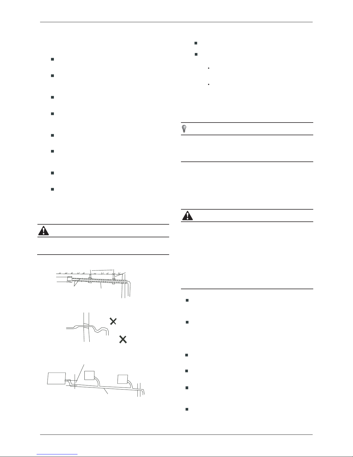
When carrying out piping connection, take care not to let
air substances go into refrigeration cycle.
Otherwise, it will cause lower capacity, abnormal high
pressure in the refrigeration cycle, explosion and injury.
Do not modify the length of the power supply cord or use
of extension cord, and do not share the single outlet with
other electrical appliances.
Otherwise, it will cause fire or electrical shock.
Carry out the specified installation work after taking into
account strong winds, typhoons or earthquakes.
Improper installation work may result in the equipment falling
and causing accidents.
CAUTION
WARNING
WARNING
CONTENTS PAGE
PRECAUTIONS........................................................................................1
INSTALLATION INFORMATION............................................................... 2
ACCESSORIES ......................................................................................3
INSPECTING AND HANDLING THE UNIT.................................................4
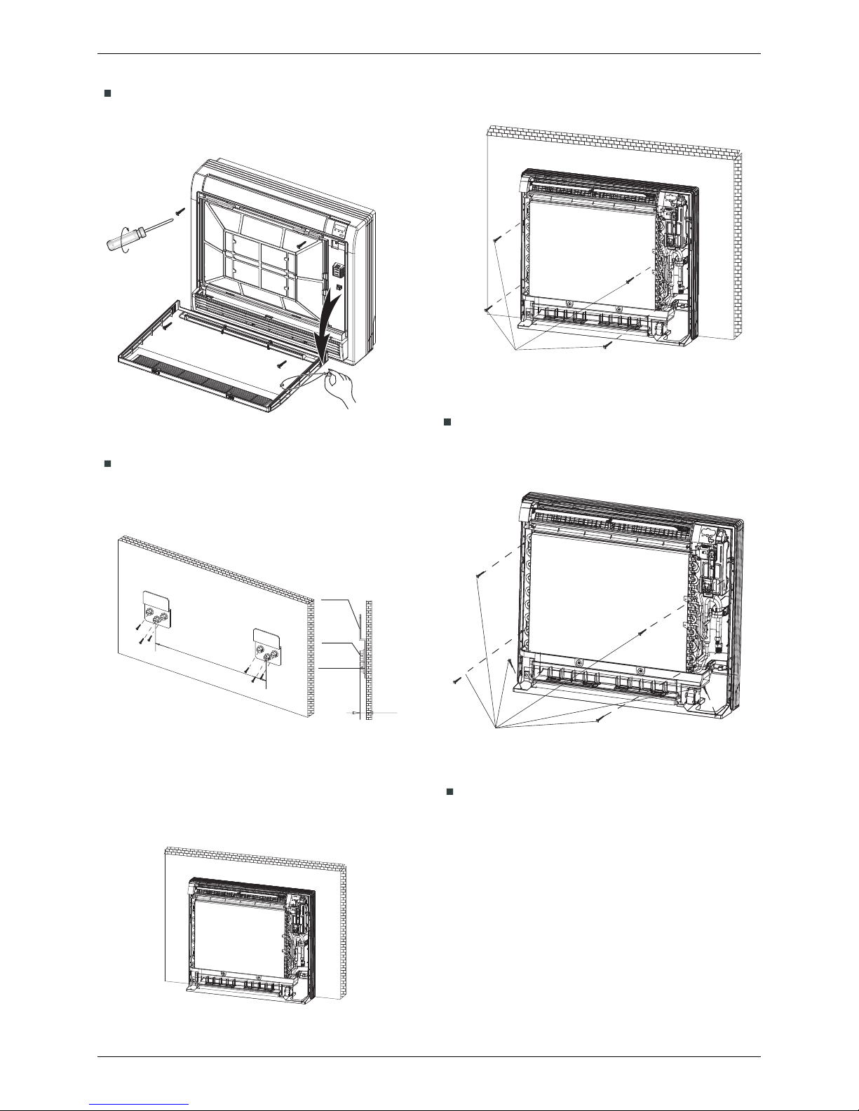
INDOOR UNIT INSTALLATION.................................................................4
CONNECT THE DRAIN PIPE....................................................................6
INSTALL THE CONNECTING PIPE...........................................................6
WIRING...................................................................................................9
CONTROL..............................................................................................12
9.1 Main board Code designation
Installation manual Console
1
TEST OPERATION.................................................................................14
TROUBLESHOOTING..................................................................13

To install properly, please read this "installation manual" at
first.
The air conditioner must be installed by qualified persons.
When installing the indoor unit or its tubing, please follow
this manual as strictly as possible.
If the air conditioner is installed on a metal part of the
building, it must be electrically insulated according to the
relevant standards to electrical appliances.
When all the installation work is finished, please turn on
the power only after a thorough check.
Regret for no further announcement if there is any change
of this manual caused by product improvement.
2. INSTALLATION INFORMATION
Ground the air conditioner.
Do not connect the ground wire to gas or water pipes,
lightning rod or a telephone ground wire.Incomplete
grounding may result in electric shocks.
Be sure to install an earth leakage breaker.
Failure to install an earth leakage breaker may result in
electric shocks.
Connect the outdoor unit wires , then connect the indoor
unit wires.
You are not allow to connect the air conditioner with the
power source until wiring and piping the air conditioner is
done.
While following the instructions in this installation
manual, install drain piping in order to ensure proper
drainage and insulate piping in order to prevent
condensation.
Improper drain piping may result in water leakage and
property damage.
Install the indoor and outdoor units, power supply wiring
and connecting wires at least 1 meter away from
televisions or radios in order to prevent image
interference or noise.
Depending on the radio waves, a distance of 1 meter may not
be sufficient enough to eliminate the noise.
The appliance is not intended for use by young children
or infirm persons without supervision.
Don't install the air conditioner in the following locations:
There is petrolatum existing.
There is salty air surrounding (near the coast).There is
petrolatum existing.
There is salty air surrounding (near the coast). If this can't
be avoided, choose a anticorrosive model.
There is caustic gas (the sulfide, for example) existing in
the air (near a hot spring).
The Volt vibrates violently (in the factories).
In buses or cabinets.
In kitchen where it is full of oil gas.
There is strong electromagnetic wave existing.
There are inflammable materials or gas.
There is acid or alkaline liquid evaporating.
Other special conditions.
If the refrigerant leaks during installation, ventilate the
area immediately.
Toxic gas may be produced if the refrigerant comes into the
place contacting with fire.
The temperature of refrigerant circuit will be high, please
keep the interconnection cable away from the copper
tube.
After completing the installation work, check that the
refrigerant does not leak.
Toxic gas may be produced if the refrigerant leaks into the
room and comes into contact with a source of fire, such as a
fan heater, stove or cooker.
INSTALLATION ORDER
Select the location;
Install the indoor unit;
Install the outdoor unit;
Install the connecting pipe ;
Connect the drain pipe;
Wiring;
Test operation.
CAUTION
9.1 Main board Code designation
Installation manual Cassette 4 way compact
2

3. ACCESSORIES
Table 3-1
Please check whether the following fittings are of full scope. If there are some spare fittings , please restore them carefully.
Fig.3-1
Never throw or beat the controller.
Before installation, operate the remote controller to determine its location in a
reception range.
Keep the remote controller at least 1m apart from the nearest TV set or stereo
equipment. (it is necessary to prevent image disturbances or noise interferences.)
Do not install the remote controller in a place exposed to direct sunlight or close to a
heating source, such as a stove.
Note that the positive and negative poles are right positions when loading batteries.
This manual is subject to changes due to technological improvement without further
notices.
Cautions on remote controller installation:
Remote controller
holder
Mounting screw B
ST2.9x10-C-H
QUANTITYSHAPENAME
1.Hook
8. Installation manual
3. Remote controller
4. Frame
6. Alkaline dry batteries (AM4)
2
1
1
2
2
1
Installation fittings
Remote controller & Its Frame
Others
5. Mounting screw(ST2.9×
10-C-H)
2. Mounting screw(ST3.9×
25-C-H)
10
7. Remote controller manual 1
9. Remote alarm signal wires 1
10. Remote control signal wires 1
11. Flexible hose tube 1
Remote
controller
RESET
TIME ON
TIME OFF
CLOCK
SWING
AIR DIRECTION
OK
ECO
SWING
MODE FAN
SPEED
0
LOCK
C/H
AUTO
COOL
DRY
HEAT
FAN
TEMP
SET
CLOCK
SET
HOUR
FANSPEED
RESET
TIMEON
TIMEOFF
CLOCK
SWING
AIRDIRECTION
OK
ECO
SWING
MODE FAN
SPEED
0
LOCK
C/H
AUTO
COOL
DRY
HEAT
FAN
TEMP
SET
CLOCK
SET
HOUR
FANSPEED
1
12.Copper:Use for pipe connection
of engineering installation
9.1 Main board Code designation
Installation manual Cassette 4 way compact
3

5. INDOOR UNIT INSTALLATION
4. INSPECTING AND HANDLING THE UNIT
At delivery, the package should be checked and any damage
should be reported immediately to the service agent.
When handling the unit, take into account the following:
Fragile, handle the unit with care.
Keep the unit upright in order to avoid compressor
damage.
Choose on before hand the path along which the unit is
to be brought in.
Move this unit as originally package as possible.
When lifting the unit , always use protectors to prevent
belt damage and pay attention to the position of the
unit’s centre of gravity.
Keep indoor unit, outdoor unit, power supply wiring and
transmission wiring at least 1 meter away from televisions and
radios. This is to prevent image interference and noise in
those electrical appliances. (Noise may be generated
depending on the conditions under which the electric wave is
generated, even if 1 meter is kept.)
When run some of the units among the indoor units in heating
mode, voice of refrigeration flowing comes from some other
non-operating indoor units, however, this is a normal
phenomena.
When you are going to install the unit at a quiet requirement
place, please consult the local distributor firstly.
There is enough room for installation and maintenance.
(Refer to Fig.5-1 and Fig.5-2)
The outlet and the inlet are not impeded, and the
influence of external air is the least.
The air flow can reach throughout the room.
The connecting pipe and drainpipe could be extracted out
easily.
There is no direct radiation from heaters.
5.1 Installation place
The indoor unit should be installed in a location that meets
the following requirements:
CAUTION
Fig.5-1
Fig.5-2
Fig.5-3
≥100mm
195mm
≥100mm
≥100mm
Hook
≥1000mm
700mm 210mm
600mm
(unit˖mm)
9.1 Main board Code designation
64
)007(
431
591
591
62
05
475
)006(
061
35
53
446
105
052
210
1 04
032
Installation manual Cassette 4 way compact
4

5.2 Install the main body
Fig.5-5
Hang the indoor unit on the hook.
(Refer to Fig.5-6)
(The bottom of body can touch with floor or suspended,
but the body must install vertically.)
For wall installations, secure hook using 6 screws and the
indoor unit using 4 screws
Fix the hook with tapping screw onto the walll which can
support the weight of the indoor unit.(Refer to Fig.5-5˅
Fig.5-6
Fig.5-8
Fig.5-4
195mm
Hook
Tapping
screw
Washer
˘mm
9.1 Main board Code designation
Removing front grille
1) Open the front panel.
2) Remove the 4 screws and remove the front grille while
pulling it forward (3 tabs).
Attach the front panel and front grille in their original positions
once all connections are complete.
For floor i
nstallations,
secure the indoor unit using 6 screws.
( Do not forget to secure to the rear wall.)(Refer to Fig.5-8)
●
Fig.5-7
●
Using 4 screws to secrew the indoor unit.
(Refer to
Fig.5-7)
●
Installation manual Cassette 4 way compact
5

7. INSTALL THE CONNECTING PIPE
CAUTION
All field piping must be provided by a licensed
refrigeration technician and must comply with the
relevant local and national codes.
Do not let air, dust, or other impurities fall in the pipe
system during the time of installation.
The connecting pipe should not be installed until the
indoor and outdoor units have been fixed already.
Keep the connecting pipe dry, and do not let moisture in
during installation.
Execute heat insulation work completely on both sides
of the gas piping and the liquid piping. Otherwise, this
can sometimes result in water leakage.
The Procedure of Connecting Pipes
7.1
Drill a hole in the wall (suitable just for the size of the wall
conduit), then set on the fittings such as the wall conduit and
its cover.
Bind the connecting pipe and the cables together tightly with
binding tapes.
Pass the bound connecting pipe through the wall conduct
from outside. Be careful of the pipe allocation to do on
damage to the tubing.
Connect the pipes. Refer to "How to Connect the pipes" for
details.
Expel the air with a vacuum pump. Refer to "How to expel the
air with a vacuum pump" for details.
Open the stop values of the outdoor unit to make the
refrigerant pipe connecting the indoor unit with the outdoor
unit in fluent flow.
Check the leakage. Check all the joints with the leak detector
or soap water.
6. CONNECT THE DRAIN PIPE
1.5m~2m
Insulating
material
Downward declivity
lower than 1/100
Bend
S shape
VP30
Downward declivity
lower than 1/100
Put as deep as possible
(about 10cm)
Fig. 6-1
NOTE
All the pictures in this manual are for explanation purpose only.
They may be slightly different from the air conditioner you
purchased(depend on model).The actual shape shall prevail.
The outlet has PTI screw bread, Please use sealing
materials and pipe sheath(fitting) when connecting PVC
The drain pipe of indoor unit must be heat insulated, or it
will condense dew, as well as the connections of the
indoor unit.
Hard PVC binder must be used for pipe connection, and
make sure there is no leakage.
With the connection part to the indoor unit, please be
noted not to impose pressure on the side of indoor unit
pipes.
When the declivity of the drain pipe downwards is over
1/100, there should not be any winding.
The total length of the drain pipe when pulled out
traversely shall not exceed 20m, when the pipe is over
long, a prop stand must be installed to prevent winding.
Refer to the figures on the right for the installation of the
pipes.
The distance between the end of the drain pipe and the
floor or the bottom of the waterspout must be more than
50mmˈand do not put it in the water. when the condense
dew directly discharge to the slotˈthe drain pipe must be
bend to make a U-shanped block to interdict the stench.
6.1 Install indoor unit drain pipe
Make sure all the connecting point of the drainage system
is sealed to prevent leakage.
CAUTION
6.2 Drainage test
Check whether the drainpipe is unhindered
New built house should have drain test done before
paving the ceiling.
Stow water of about 500ml to the water receiver
through the stow tube.
Turn on the power,
set the air conditioner under
the mode of “COOLING”.
Check whether the
drainpipe is unhindered(According to the length of
the drainpipe, it drained after one minute.), and
whether there’s a l
eakage exisit in all the connect-
ing point
9.1 Main board Code designation
Installation manual Cassette 4 way compact
6

CAUTION
Be sure to with insulating materials cover all the exposed
parts of the flare pipe joints and refrigerant pipe on the
liquid-side and the gas-side. Ensure that there is no gap
between them.
Incomplete insulation may cause water condensation.
Fig.7-1
Open the front panel
1
Slide the two stoppers on the left and right sides inward
until they click .(Refer to Fig.7-1)
How to take indoor unit apart to connect
the pipes
Remove the face plate .
3
Remove the four screws.(Refer to Fig.7-2)
Opening bottom of face plate for an angle that is 30
degrees, then the top of face plate will be take up.(Refer to
Fig.7-3)
Fig.7-3
Remove the front panel .
2
Remove the string. (Refer to Fig.7-2)
Allowing the front panel to fall forward will enable you to
remove it.
Fig.7-2
Cover the joints of the connecting pipe with the soundproof /
insulating sheath (fittings), and bind it well with the tapes to
prevent leakage.
Flaring
1
Cut a pipe with a pipe cutter. (Refer to Fig.7-4)
Insert a flare nut into a pipe and flare the pipe.
Refer to Table 7-1 for the dimension of flare nut spaces.
90 Lean crude burr
Fig.7-4
How to Connect the pipes
Table 7-1
Φ6.4 8.3 8.7
Φ9.5 12.0
Φ12.7 15.4
Φ15.9
Φ19.1
18.6
22.9
R0.4~0.8
45°±2
90 °
±4
A
97.2118.6N.m
61.875.4 N.m
49.560.3 N.m
32.739.9N.m
14.217.2 N.m
(mm)
min max
Pipe gauge Tightening torque Flare dimension A Flare shape
12.4
15.8
19.0
23.3
9.1 Main board Code designation
Installation manual Cassette 4 way compact
7

2
Bend the tubing in proper way. Do not harm to them.
(Refer to Fig.7-5)
Connect the indoor unit at first, then the outdoor
unit.
Too large torque will harm the bellmouthing and too small
will cause leakage. Please determine the torque
according to Table 7-2.
After the connecting work is finished, be sure to check
that there is no gas leak.
The bending angle should not exceed 90.
Bending position is preferably in the middle of the
bendable pipe. The larger the bending radius the better it
is.
Do not bend the pipe more than three times.
When connecting the flare nut, coat the flare both inside
and outside with either oil or ester oil and initially tighten
by hand 3 or 4 turns before tighting firmly. (Refer to
Fig.7-6)
Bend the pipe with thumb
min-radius 100mm
How to expel the air with a vacuum pump
Stop valve operation introduction
1 Opening stop valve
1.
2.
3.
Remove the cap and turn the valve
counterclock-wise with the hexagon wrench.
Turn it until the shaft stops.Do not apply excessive force
to the stop valve. Doing so may breakthe valve body, as
the valve is not a backseat type. Always use the special
tool.
Make sure to tighten the cap securely.
Fig.7-5
Fig.7-6
Fig.7-7
Be sure to use both a spanner and torque wrench
together when connecting or disconnecting pipes to /from
the unit. (Refer to Fig.7-7)
Make sure to tighten the cap securely.
For the tightening torque,refer to the table below.
2 Closing stop valve
1.
2.
Remove the cap and turn the valve clockwise with the
hexagon wrench.
Securely tighten the valve until the shaft contacts the
main bodyseal.
CAUTION
CAUTION
Always use a charge hose for service port connection.
After tightening the cap, check that no refrigerant leaks are
present.
Table 7-2
Tightening torque N M (Turn clockwise to close)
Stop
Valve size
Shaft (valve body)
Cap
(Valve lid)
Φ6.4
Hexagonal
wrench 4 mm
Φ12.7
Mainte-
nance nut
1822
13.516.55.46.6
8.19.9
11.513.9
1
2
4
3
5
7
6
Using the vacuum pump
Loosen and remove the maintenance nuts of stop valves A
and B, and connect the charge hose of the manifold valve to
the service port of stop valve A. (Be sure that stop valves A
and B are both closed)
Connect the joint of the charge hose with the vacuum pump.
Open the Lo-lever of the manifold value completely.
Turn on the vacuum pump. At the beginning of pumping,
loosen the maintenance nut of stop valve B a little to check
whether the air comes in (the sound of the pump changes,
and the indicator of compound meter turns below zero). Then
fasten the maintenace nut.
When the pumping has finished, close the Lo-lever of the
manifold valve completely and turn off the vacuum
pump.Make pumping for 15 minutes or more and check that
the compound meter indicates -76cmHg(-1X10 Pa)
Loosen and remove the cap of stop valves A and B to open
stop valve A and B completely, then fasten the cap.
Disassemble the charge hose from the service port of stop
valve A, and fasten the nut.
5
Fig.7-9
Fig.7-8
service port
cap
maintenance nut
Stop valve
Gas side
Liquid side
hexagon holeshaftseal
Outdoor
unit
Indoor
unit
AC
D
B
9.1 Main board Code designation
Installation manual Cassette 4 way compact
8

Fig.7-10
Pressure meterMulti-meter
-76 cmHg
Lo-lever
Lo-lever
Charge hose Charge hose
Vacuum pump
Hi-lever
Manifold valve
8. WIRING
CAUTION
The appliance shall be installed in accordance with
natioanl wiring regualtions.
The air conditioner should use separate power supply
with rated voltage.
The external power supply to the air conditioner should
have ground wiring, which is linked to the ground wiring
of the indoor and outdoor unit.
The wiring work should be done by qualified persons
according to circuit drawing.
An all-pole disconnection device which has at least 3mm
separation distance in all pole and a residual current
device(RCD)with the rating of above 10mA shall be
incorporated in the fixed wiring according to the national
rule.
Be sure to locate the power wiring and the signal wring
well to avoid cross-disturbance.
Do not turn on the power until you have checked
carefully after wiring.
NOTE
Remark per EMC Directive 2004/108/EC
For to prevent flicker impressions during the start of the
compressor (technical process) ,following installation
conditions do apply.
The power connection for the air conditioner has to be
done at the main power distribution. The impedance of
the distribution has to be low impedance.
No other equipment has to be connected with this power
line.
For detailed installation acceptance please refer to your
power supplier, if restrictions do apply for products like
washing machines, air conditioners or electrical ovens.
The temperature of refrigerant circuit will be high, please
keep the interconnection cable away from the copper
tube.
1
2
3
For power details of the air conditioner refer to the rating
plate of the product.
For any question contact your local dealer.
4
5
Electric Wiring
8.1
7.2
Refrigerant pipe installation
6
9.1 Main board Code designation
Ventilate the air if there was any refrigerant leakage during
installation.Leaked refrigerant will generate poisonous gas if
meeting fire.
Make sure there is no refrigerant leakage after installation.
Leaked refrigerant will generate poisonous gas if meeting fire.
Allowed Length and Drop of Piping
Requirements are different when installing the Outdoor
Unit,please refer to Outdoor Unit Installation Manual for
detailed information.
Material and Size of the Piping
Size(mm)
Pipe Material Copper Pipe for Air Conditioner
Model
Φ12.7
Φ6.4
22-45
(Gas side)
(Liquid side)
Refrigerant Volume to Be Added
Refrigerant Volume to be added is calculated according to
Outdoor Unit Installation Manual .
Be save to add refrigerant measuring by a scale.
If refrigerant volume added is inadequate (too much or
insufficient),the compressor malfunction will be caused.Be
sure to calculate the refrigerant volume carefully.
The service man should note down the piping length and
refrigerant volume added on the nameplate, which is on the
Electric Control Box Cover of outdoor unit for to diagnose the
compressor when compressor malfunction occurs.
Table 7-3
CAUTION
CAUTION
Installation manual Cassette 4 way compact
9

The installation bearer of sensing device rotated to another
side, and then takes off cover of electrical box. (Refer to
Fig.8-1)
Connect the cable
8.2
Table 8-1
MODEL 22~45
Power
Phase
Volt and frequency
Manual switch
Safty fuse
1-Phase
220-240V~ 50Hz/60Hz
15A
15A
Indoor
unit
power
wiring
Powerwire
Ground wiring 2.5mm2
Single wire 2.5mm2
Outdoor
/indoor
signal
wire
Amount 3
Diameter shielded wire 0.75mm2
Too small capacitance lead to wiring overheating, and will
cause a burning machine accident. Power specifications
refers to Table 8-1.
Installation bearer
of sensing device
Fig.8-1
Connect the connective cables to the terminals as identified
with their respective mached numbers on the terminal block of
indoor and outdoor units.
Re-install the Indoor unit and outdoor unit
The Specification of Power
8.3
8.4
Wiring of Indoor Unit Power Supply and
Signal Wire
The indoor unit should use dedicated power supply
different from the outdoor unit.
The power supplycurrent leakage protection device and
the switch of the indoor unit which connect to the same
outdoor unit should be universal.
The indoor unit power supply wire connect to port L and
port N, port connect to the ground wire, the indoor unit
signal wire connect to portPport Q and port E whichcor-
respond to port Pport Q and port E of the outdoor unit.
Indoor unit power
220-240V~ 50Hz
Fig.8-3
Fig.8-4
XYE
The wires connected
indoor unit to outdoor unit
PQLN E
The wires connected indoor unit
to central control monitor
Remove the electric box1 screw. (Refer to Fig.8-1)
9.1 Main board Code designation
Installation manual Cassette 4 way compact
10

It’s needed to add a remote control and remote alarm to
the unit. Take out the white short connector in the CN21
port from the main panel, accordingly joint the attached
connective wires corresponding to the CN21 and
REMOTE_ERROR ports, which color is the same as the
color of the ports. The wires go all through the plastic
cabinet above the main control board and lead out to from
the wire outlet. They must be fixed together with the other
wires at the hole orderly, avoid from wire be pressured by
the J-box.
CAUTION
8.5
Wiring connection diagram
Fig.8-5
34(
34(
(open)
3
4
the outdoor unit
signal wire between outdoor units
signal wire of
indoor/outdoor unit
group control
the shiled layer connect to shield wire
all shield terminals of shield wires connect to
the COMM terminal˼˃
The indoor unit which at the terminal of communication system should
paraliel connect a impedance between port P and port Q.
matching
resistor
8.6
Code switch function
temperature modification code
Air outlet selection switch
Fig.8-6
Select the code function.
ON OFF
ON
12
OFF
ON
12
OFF
Description˖
For the first code:
ON —— the lower air outlet open.
OFF —— the lower air outlet close.
For the second code:
ON —— “1”
OFF —— “0”
“11” —— +6°C
“10” —— +4°C
“01” —— +2°C
“00” —— +0°C
For the third code:
ON —— super high fan speed.
OFF —— extreme super high fan speed.
1
23
Temperature corrected code "+0" means˖in the heating,
T1>TS+0°C, the units' capacity should be 0.
Temperature corrected code "+2"means˖in the heating,
T1>TS+2°C, the units' capacity should be 0.
Temperature corrected code "+4"means˖in the heating,
T1>TS+4°C, the units' capacity should be 0.
Temperature corrected code "+6"means˖in the heating,
T1>TS+6°C, the units' capacity should be 0.
8.7
Telecontrol function
When the system detects the circuit is open (low electrical
level would be input to the chip detected terminal, when CN21
port without short connected / SW3 switched in OFF), it would
responds as follows:
Turn off the remote controller.
The system would receive and remember the remote/wire
control signal (but without settle the failure).
The display lamp flashing in 1Hz, as far as the chip
detects high electrical level has been input.
System will not relieve the failure and output the
malfunction information.
When the system detects the circuit is close (high electrical
level would be input to the chip detected terminal, when CN21
port has short connected / SW3 switched in ON), it would
responds as follows:
If the latest memory is the shut off mode, the unit would
keeping in shut off, if the memory is the open mode, unit
would restart again.
The starting operation mode is equal to memory function.
Installation manual Cassette 4 way compact
11

9.1 Main board Code designation
Installation manual Cassette 4 way compact
12
9.1 Switch setting
9. CONTROL
Ș1 means factory test mode
Ș0 means add. auto searching mode
(default setting)
Ș1 means DC fan is chosen
Ș0 means AC fan is chosen
Ș
Ș01 means DC fan static pressure is 1
(reserved)
Ș
Ș
6:
21
6:
21
6:
21
6:
21
6:
21
6:
21
6:definition
Ș00 means the temperature is 15
degrees when shutting down the unit
for cold wind proof.
Ș01 means the temperature is 20
degrees when shutting down the
unit for cold wind proof.
Ș10 means the temperature is 24
degrees when shutting down the
unit for cold wind proof.
Ș11 means the temperature is 26
degrees when shutting down the
unit for cold wind proof.
Ș00 means the time of stopping
indoor fan is 4 minutes
Ș01 means the time of stopping
indoor fan is 8 minutes
Ș10 means the time of stopping
indoor fan is 12 minutes
Ș11 means the time of stopping
indoor fan is 16 minutes
6:
21
6:
21
6:
21
6:
21
6:
21
6:
21
6:
21
6:
21
6:definition
Ș00 means temperature compensation is
6 degrees under heating mode Ș10 means temperature compensation
is 4 degrees under heating mode
Ș11 means temperature compensation
is 8 degrees under heating mode
Ș01 means temperature compensation is
2 degrees under heating mode
6:
21
6:
21
6:
21
6:
21
6:definition
Reserved
Reserved
Reserved
Ș
1 means auto wind under auto mode
Ș
0 means auto wind under non auto mode
6:
21
6:
21
6:definition
--definition
J1 no Jumpers means power
off memory function
J1 Jumpers means no power
off memory function
reserved
-
-
-
Reserved
6:
21
6:
21
Standard configure
Last one in the network
6:definition
21
21
0HDQV
0HDQV
definition

The system together have 64units(0-63),everyone has only
system addresscode,If two addresses are the same in one
system , the abnormal operation will occur.
Please switch off the power before setting,otherwise the
unexpected error will occur.
CAUTION
9.3 Network address set
1) Network address is set by communication of indoor and
outdoor unit; the address is the same as indoor address, there
is no need to set separately.
2) The central control of indoor units can be done on outdoor
unit, there is no need to control indoor unit separately, for
details please refer to V4+ outdoor unit manual.
3) For previous control of indoor units, the network can be set
by connecting (X,Y,E) terminals, there is no need to set
network address.
Capacity setting
9.2
Horsepower code
ENC1
POWER_S
Table: 9-1
ENC1
1
2
3
2200 W
Switch cord
Switch For set horsepower
CapacityHorsepower
Note: No one are
permitted to alter
the cooling output
which be set
before shipping
from factory,
except licensed
maintain
personnel. 4500 W
3600 W
2800 W
0
Set the PCB board toggle of the indoor unit electric control box
by the different use. After setting, make sure to switch off the
power, and then switch on it. If you don’t switch on the power,
the capacity you set can not implement.
9.1 Main board Code designation
Installation manual Cassette 4 way compact
13
Table.10-1
NO. Type Contents
LED Lamp flash
Remarks
The evaporator
sensor check
point is abnomal
or room temp.
sensor is
abnormal.
Indoor/outdoor unit
communication
is abnormal
Water level switch
is abnormal
Mode conflict
The run lamp
flashes fast
The timer lamp
flashes fast
The alarm lamp
flashes fast
The defrost lamp
flashes fast
After the malfunctions
disappear, it restores
automatically.
After the malfunctions
disappear, it restores
automatically.
After the malfunctions
disappear, it restores
automatically.
When the indoor unit
turns to heating mode
or is turned off, the
alarm will disappear.
1
2
3
4
5
Malfun-
ction
Malfun-
ction
Malfun-
ction
Malfun-
ction
Alarm
After the malfunctions
disappear, it restores
automatically.
Outdoor unit
is abnormal
The alarm lamp
flashes slowly
6
7
4 LED flash
togather
8
M_Home
mismatching
EEPROM error
Defrost LED flash
slowly
No address
when first time
power on
Timer LED and
run LED flash
togather
Malfun-
ction
Alarm
Alarm
After the malfunctions
disappear, it restores
automatically.
After the malfunctions
disappear, it restores
automatically.
When the indoor unit is
replaced with a correct
one , the alarm will
disappear
E2
E3
E4
E1
Ed
EE
E0
H0
E7
FE
10. TROUBLESHOOTING

Installation manual Cassette 4 way compact
14
According to the user's requirement, install the remote
controller frame where the remote controller's signal can
reach the indoor unit smoothly.
Test operation
11. TEST OPERATION
The test operation must be carried out after the entire
installation has been completed.
Please confirm the following points before the test operation:
The indoor unit and outdoor unit are installed properly.
Tubing and wiring are correctly completed.
The refrigerant pipe system is leakage-checked.
The drainage is unimpeded.
The heating insulation works well.
The ground wiring is connected correctly.
The length of the tubing and the added stow capacity of
the refrigerant have been recorded.
The power voltage fits the rated voltage of the air
conditioner.
There is no obstacle at the outlet and inlet of the outdoor
and indoor units.
The gas-side and liquid-side stop valves are both opened.
The air conditioner is pre-heated by turning on the power.
Set the air conditioner under the mode of "COOLING" with the
remote controller, and check the following points. If there is
any malfunction, please resolve it according to the chapter
"Troubleshooting" in the "Owner's Manual".
The indoor unit
Whether the switch on the remote controller works well.
Whether the buttons on the remote controller works well.
Whether the air flow louver moves normally.
Whether the room temperature is adjusted well.
Whether the indicator lights normally.
Whether the temporary buttons works well.
Whether the drainage is normal.
Whether there is vibration or abnormal noise during
operation.
Whether the air conditioner heats well in the case of the
HEATING/COOLING type.
The outdoor unit
Whether there is vibration or abnormal noise during
operation.
Whether the generated wind, noise, or condensed of by
the air conditioner have influenced your neighborhood.
Whether any of the refrigerant is leaked.
A protection feature prevents the air conditioner from being
activated for approximately 3 minutes when it is restarted
immediately after shut off.
CAUTION

ASK FOR MORE INFORMATION
Phone: (+34) 93 446 27 80
eMail: [email protected]
TECHNICAL ASSISTANCE
Phone: (+34) 93 652 53 57
MVD
www.mundoclima.com
This manual suits for next models
1
Table of contents
Popular Music Mixer manuals by other brands

Tascam
Tascam 388 Studio 8 operation & maintenance

Digital Audio Labs
Digital Audio Labs Livemix CS-DUO quick start guide

SoundCraft
SoundCraft Spirit Folio Rac Pac Product guide

Magnimage
Magnimage MIG-H8 user manual

DAVIS
DAVIS Vantage Pro2 6312 Console Console manual

Audio 2000
Audio 2000 AMX7322 owner's manual