
© Munters Corporation, November 2023
4QM1410r0
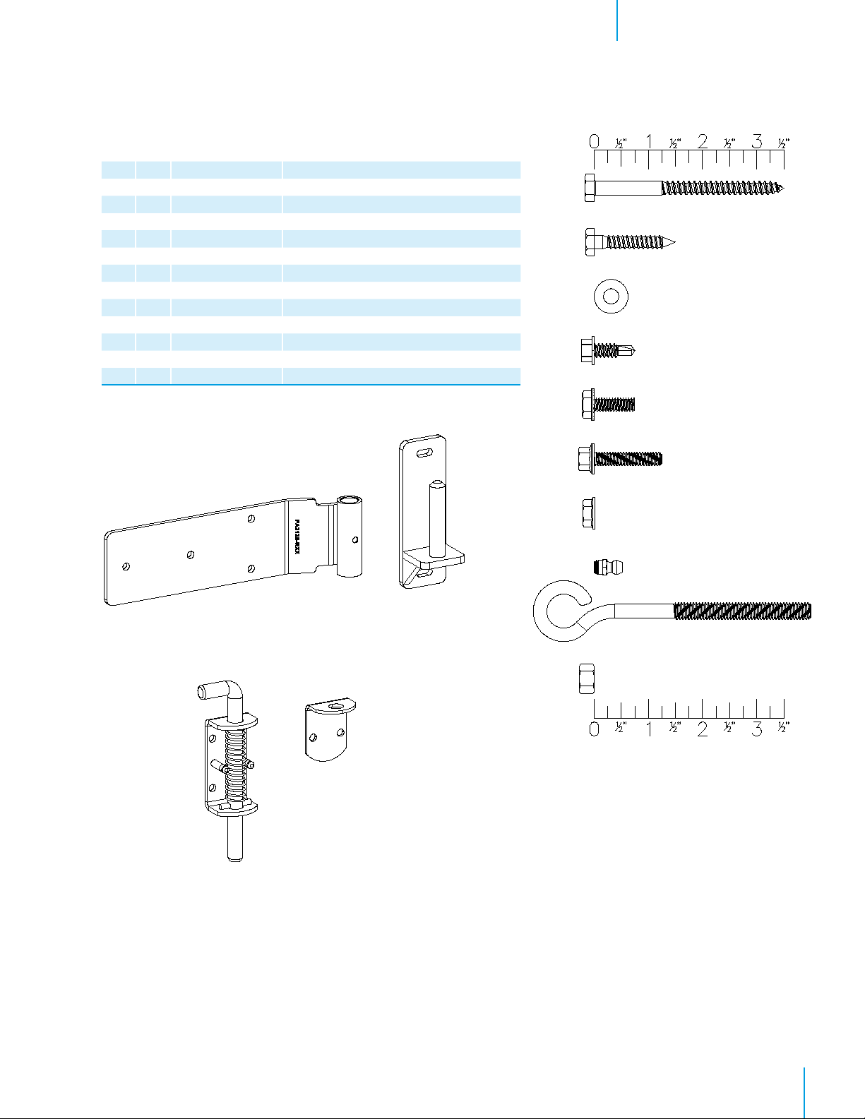
1.1 Parts List
Unpacking the Equipment 1.
Before beginning installation, check the overall condition of the equipment. Remove packing materials, and examine
all components for signs of shipping damage. Any shipping damage is the customer’s responsibility and should be re-
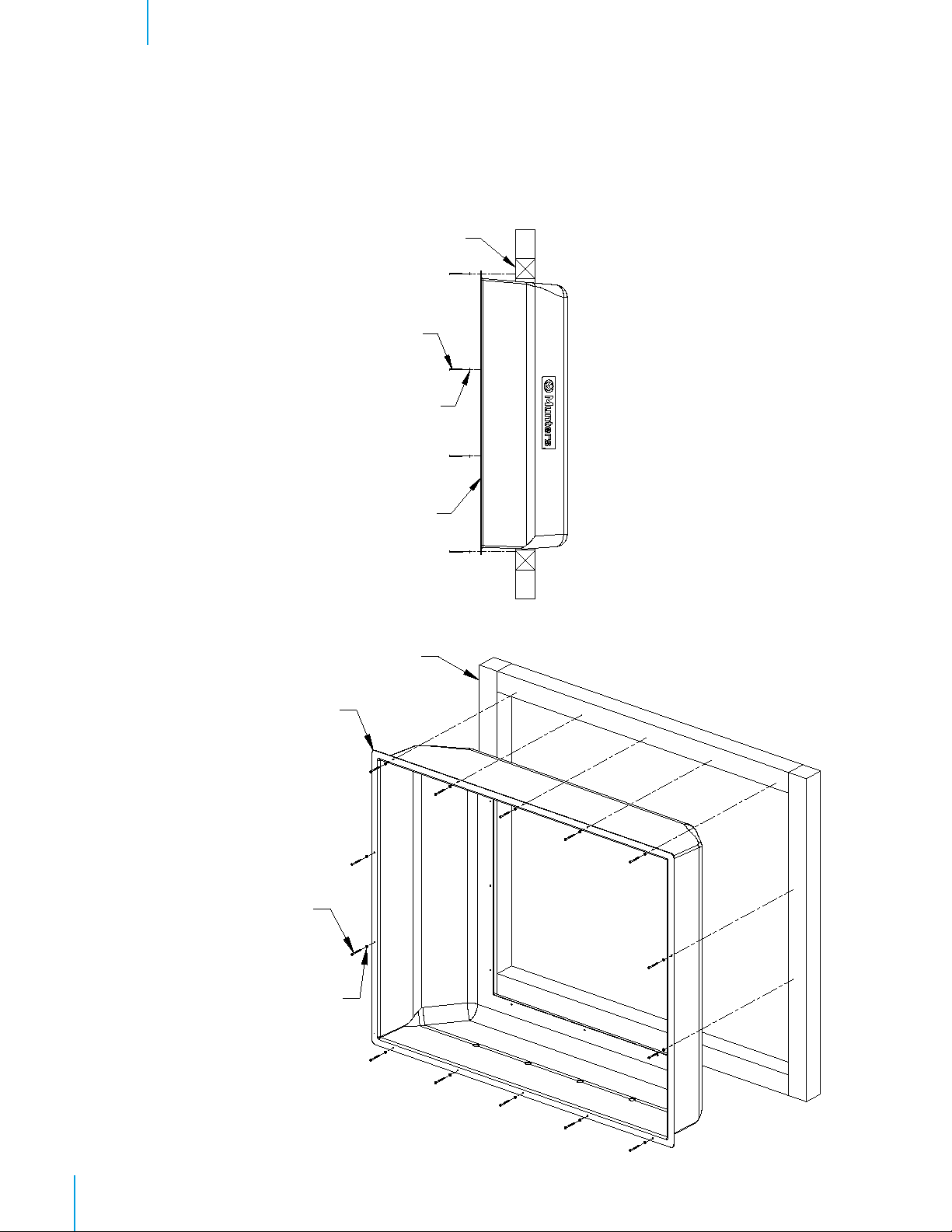
ported immediately to your freight carrier. LTX Housing is shipped with all accessories for assembly, (fan not included).
Each LTX Housing Includes:
Qty Cat. No. Description
1 FA2136 - FA2151 - FA2155 LTX Housing, 36LTX - 51LTX - 55LTX, FG
1 FA1621 Right/Left LTX Doors Kit
1 BK2001 Bulk Pack, R.H. Door Side Panels
1 FA2103 Door Hinge Panel, GZ
1 FA2105 R.H. Center Door Panel, GZ
1 BK2002 Bulk Pack, L.H. Door Side Panels
1 FA2103 Door Hinge Panel, GZ
1 FA2107 L.H. Center Door Panel, GZ
1 BK2003 Bulk Pack, R.H. Door Top/Bottom Panels
2 FA2104 R.H. Top/Bottom Door Panel, GZ
2 FA2110 1/2 Darkout Bracket, 36”L., GZ
1 BK2004 Bulk Pack, L.H. Door Top/Bottom Panels
2 FA2106 L.H. Top/Bottom Door Panel, GZ
2 FA2111 1/2 Darkout Bracket, 48”L., GZ
1 BK2005 Bulk Pack, R.H. Door Corners/Hardware
1 FA2124 R.H. Center Top Corner Bracket, GZ
1 FA2125 R.H. Center Bottom Corner Bracket, GZ
2 FA2123 Top/Bottom Hinge Panel Corner Bracket, GZ
2 FA2120 [H] Lift-Off Style, Leaf Hinge, CTD-STEEL, BK
2 FA2121 [J] Lift-Off Style Hinge Pin, CTD-STEEL, BK
22’ KA7101 Brush Seal, 0.31”W. x 0.75”H. BLK, PVC
1 HP1188 Hardware Package One Door
1 HP1189 Hardware Package TEK Screws One Door
1 BK2006 Bulk Pack, L.H. Door Corners/Hardware
1 FA2126 L.H. Center Top Corner Bracket, GZ
1 FA2127 L.H. Center Bottom Corner Bracket, GZ
2 FA2119 Top/Bottom Hinge Panel Corner Bracket, GZ
2 FA2120 [H] Lift-Off Style, Leaf Hinge, CTD-STEEL, BK
2 FA2121 [J] Lift-Off Style Hinge Pin, CTD-STEEL, BK
22’ KA7101 Brush Seal, 0.31”W. x 0.75”H. BLK, PVC
1 HP1188 Hardware Package One Door
1 HP1189 Hardware Package TEK Screws One Door
1 BK2007 Bulk Pack, Darkout, Rods & Gap Cover
1 FA2114 Light Gap Cover, Darkout, GZ
1 FA2147 Light Gap Cover Bracket, GZ
2 FA2141 J-Hook Rod, 2 Ends, 0.25”D, 71”L, STL
2 FA2142 J-Hook Rod, 2 Ends, 0.25”D, 66”L, STL
2 FA2130 Reinforcing Plate, LTX Housing, 60”L., CTD-GZ
Continued on next page


 user manual")


