OUTDOOR HELIUM HOTSPOT OVERVIEW
Frequency Supported Regions
915 Mhz US915, AU915, AS923-1/2/3/4, KR920
The frequency is set upon initialisation by the Helium Network.
Antenna Specications
Specication 470Mhz Model 868 & 915Mhz Models
Frequency Range 420-480 860-930 Mhz
Peak Gain 3 dBi 3 dBi
VSWR ≤1.5 ≤1.5
Input Impediance 50 Ohms 50 Ohms
Length 50CM 30CM
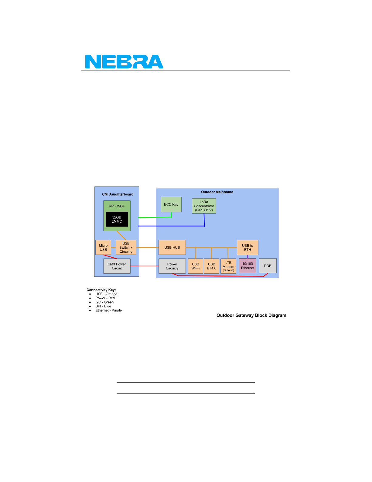
Hardware Overview
Mainboard Layout
Layout Contents
1. DC Barrel Jack - 2MM Pin, 6.5MM Barrel centre positive. Recommended
PSU 12V @1.5A.
2. LAN Connector - RJ45 Connector wired to the Ethernet & POE Modules.
3. Power Jumper - 3 Pin jumper to select power source, place in position
1-2 for POE, or 2-3 for DC Jack.
4. POE Module - Negotiates 802.11AF compliant connection and outputs
12V DC into the power section.
5. Power Section - Takes the 12V power source and regulates it down to
5V & 3V3 rails.
6. Ethernet Controller - 10/100 Ethernet to USB 2.0 Adaptor, Maxlinear
XR22800IL32-F. Connected to USB Hub.
7. USB Hub - 4 Port USB Hub, wired to Ethernet controller, USB port & M-
PCIE connector.
8. USB Port - USB 2.0 Type A Connector, recommended max power 250mA.
9. “Raspberry Pi” Header - 40 Pin RPi style header, please note only the
rst 24 pins are wired. (Refer to 1.1.X)
10. M-PCIE connector - M-PCIE Connector wired up to USB for connectivity,
has Micro SIM Card connected to it.
11. Micro Sim Card Slot - For use with 3G/4G Module in M-PCIE slot
12. Lora Module Connector - Designed for use with select M-PCIE LoRa Con-
centrators, these only have wired up SPI, plus GPS PPS from the GPS
Module.
4 Nebra LTD. 2021