manuals.online logo
Brands
  1. Home
  2. •
  3. Brands
  4. •
  5. NEC
  6. •
  7. Projector
  8. •
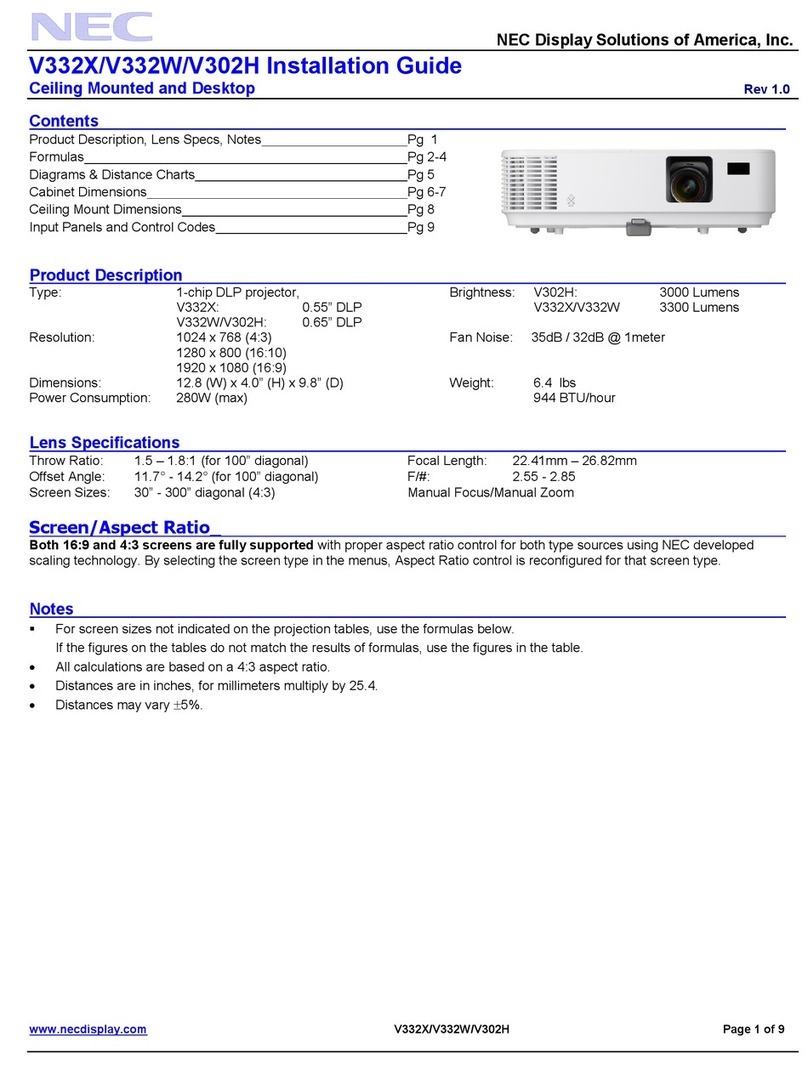
  9. NEC NP-M311W Installation instructions

NEC NP-M311W Installation instructions

Other manuals for NP-M311W

3

This manual suits for next models

132

Other NEC Projector manuals

NEC VT695 User manual

NEC

NEC VT695 User manual

NEC PA500U Series User manual

NEC

NEC PA500U Series User manual

NEC NP410 EDU User manual

NEC

NEC NP410 EDU User manual

NEC U321H User manual

NEC

NEC U321H User manual

NEC PH1000U User manual

NEC

NEC PH1000U User manual

NEC LT260 Series User manual

NEC

NEC LT260 Series User manual

NEC DLP Cinema NC2000C User manual

NEC

NEC DLP Cinema NC2000C User manual

NEC NC1700L User manual

NEC

NEC NC1700L User manual

NEC NP-PA500X User manual

NEC

NEC NP-PA500X User manual

NEC VT45KG User manual

NEC

NEC VT45KG User manual

NEC NP-M311W User manual

NEC

NEC NP-M311W User manual

NEC VT575 Series User manual

NEC

NEC VT575 Series User manual

NEC NC1100L-A User manual

NEC

NEC NC1100L-A User manual

NEC LT170 - XGA DLP Projector User manual

NEC

NEC LT170 - XGA DLP Projector User manual

NEC LT155 - MultiSync UXGA DLP Projector Assembly instructions

NEC

NEC LT155 - MultiSync UXGA DLP Projector Assembly instructions

NEC VE303 User manual

NEC

NEC VE303 User manual

NEC LT100 - MultiSync XGA DLP Projector Installation and user guide

NEC

NEC LT100 - MultiSync XGA DLP Projector Installation and user guide

NEC VT480 Series User manual

NEC

NEC VT480 Series User manual

NEC VT650 User manual

NEC

NEC VT650 User manual

NEC HT510 Series User manual

NEC

NEC HT510 Series User manual

NEC VT470 User manual

NEC

NEC VT470 User manual

NEC NC800C User manual

NEC

NEC NC800C User manual

NEC NP04CM Guide

NEC

NEC NP04CM Guide

NEC VT570 Series User manual

NEC

NEC VT570 Series User manual

Popular Projector manuals by other brands

Eiki LC-X985 Specification sheet

Eiki

Eiki LC-X985 Specification sheet

InFocus LitePro 610 quick start

InFocus

InFocus LitePro 610 quick start

Epson EH-TW5900 datasheet

Epson

Epson EH-TW5900 datasheet

FOREVER MLP-100 manual

FOREVER

FOREVER MLP-100 manual

Toshiba TDP-MT8U Specifications

Toshiba

Toshiba TDP-MT8U Specifications

Mitsubishi XD500U specification

Mitsubishi

Mitsubishi XD500U specification

Kodak Ektapro 3020 Illustrated parts list

Kodak

Kodak Ektapro 3020 Illustrated parts list

Toshiba TDP-EW25U Specifications

Toshiba

Toshiba TDP-EW25U Specifications

Barco iQ PRO G500 supplementary guide

Barco

Barco iQ PRO G500 supplementary guide

Philips LC1341 user guide

Philips

Philips LC1341 user guide

Epson PowerLite 1266 user guide

Epson

Epson PowerLite 1266 user guide

MAGINON DLP 1400S user manual

MAGINON

MAGINON DLP 1400S user manual

Toshiba TLP-380 owner's manual

Toshiba

Toshiba TLP-380 owner's manual

Philips PicoPix PPX2480/EU user manual

Philips

Philips PicoPix PPX2480/EU user manual

Hitachi CP-X605 Series Specifications

Hitachi

Hitachi CP-X605 Series Specifications

Optoma TW1692 user manual

Optoma

Optoma TW1692 user manual

Kodak EKTAPRO instruction manual

Kodak

Kodak EKTAPRO instruction manual

Optoma Optoma PRO150S datasheet

Optoma

Optoma Optoma PRO150S datasheet

manuals.online logo
manuals.online logoBrands
  • About & Mission
  • Contact us
  • Privacy Policy
  • Terms and Conditions

Copyright 2025 Manuals.Online. All Rights Reserved.

======================================================================
Control Commands for NEC Projector (Basic) Rev 4.28.11a
Copyright (C) NEC Display Solutions, Ltd. 2002-2011
----------------------------------------------------------------------
Updated on April 28, 2011
----------------------------------------------------------------------
This file contains information about NEC projector control commands.
Model Name
GT60 : GT5000/GT 6000 Series
GT50 : GT1150/GT 2150 Series
HT : HT1000/HT1100 Series
HT10 : HT410/HT510 Series
LT180 LT180
LT30 : LT25/LT30/LT35 Series
LT : LT220/LT240/LT240K/LT260/LT260K/LT 245/LT265 Series
LT80 : LT280/LT380 Series
MT70 : MT 860/MT1060/MT1065/MT1075 Series
NP60 : NP40/NP50/NP60 Series
NP62 : NP41/NP61/NP62 Series
NP1000 : NP1000/NP2000 Series
NP3150 : NP1150/NP2150/NP3150/NP3151W Series
NP4000 : NP4000/NP4001 Series
NP905 : NP905/NP901W/VT800 Series
NP600 : NP300/NP400/NP500/NP500W /NP500WS/NP600/NP600S Series
VT : VT770 Series
VT70 : VT37/VT47/VT480/VT57/VT570/VT575/VT670/VT676 Series
VT80 : VT48/VT480/VT580 Series
VT90 : VT49/VT490/VT590/VT595/VT 695 Series
VT700 : VT700
WT : WT600/WT610/WT615 Series
NP4100 : NP4100/NP4100W Series
NP3250 : NP1250/NP2250/NP3250/NP3250W Series
NP610 : NP310/NP410/NP410W /NP510/NP510W/NP510WS/NP610/NP610S Series
NP2200 : NP1200/NP2200 Series
NP216 : NP110/NP115/NP215/NP216 Series
NP64 : NP43/NP64 Series
M300 : M260X/M260W/M300X/M300W Series
P420 : P350X/P350W /P420X Series
U300 : U300X/U310W Series
V300 : V260/V260X/V200X Series
======================================================================
Contents
1. Projector Control
2. Connection Method
3. Interface Conditions
4. List of Commands
5. Command Descriptions
6. Table of Response Error Codes
======================================================================
1. Projector Control
----------------------------------------------------------------------
NEC projectors make use of control commands that control the functions of the projector via connection with a
personal computer or another device.
======================================================================
2. Connection Method
----------------------------------------------------------------------
The following 3 kinds of connection methods are available for sending and receiving control commands.
1. Serial connection using the serial port on the projector
A serial cable is required.
2. USB connection using the USB port on the projector
A USB cable is required.
3. LAN connection
3-1. LAN connection using a wired LAN card
A wired LAN card and LAN cable are required.
3-2. LAN connection using a wireless LAN card
A wireless LAN card is required.
3-3.LAN connection using the LAN port on the projector
A LAN cable is required.
3-4. LAN connection using a wireless LAN unit
A wireless LAN unit is required
Status of supported connection
* A USB cable is supplied as standard with the MT860/1060/1065/1075.
* The GT5000/6000 does not come with a USB cable.
* Note that a connection method using the supplied USB cable is not supported for the LT220/240/260.
* The serial cable, LAN card and LAN cable are separately sold.
* The WT610 replaced the WT610 and uses the same command set.
(CAUTION)
Before making connections, be sure to invalidate the standby mode of the projector and set the "idle mode". The
projector cannot use the control commands in the standby mode.
Setting method: Under projector [Projector Options] --> [Setup], enter a check for [Idle Mode] on Page 4.
( CAUTION ) (!1)
Before making connections, be sure to select [NORMAL] for [STANDBY MODE].
Setting method : From the projector's menu, select [SETUP] --> [OPTIONS(2)] -->[STANDBY MODE]--> [NORMAL].
( CAUTION ) (!2)
The projector accept the "POWER ON" command during [POWER-SAVING] mode for[STANDBY MODE].
Supplement:
(!1) Only the NP600/NP610/NP3200 series is compatible.
(!2) Only the M300 series is compatible.
[P350X/P350W/P420X Series]
STANDBY MODE: "POWER-SAVING"
Control Comm and
Serial
port
Wired
LAN port
Wireless
LAN unit
POWER ON Yes No No
Yes: Supported
No: Not supported
====================================================================
3. Interface Conditions
----------------------------------------------------------------------
Serial connection
----------------------------------------------------------------------
The communications method conforms to the RS-232C standard.
(1) (2) (3-1) (3-2) ( 3-3) (3-4)
GT5000/GT6000 Yes Yes Yes Yes Yes No
GT1150/GT2150 Yes No Yes Yes Yes No
HT410/HT510 Yes No No No No No
HT1000/HT1100 Yes No No No No No
LT180 Yes No No No No No
LT25/LT30/LT35 Yes No No No No No
LT220/LT240/LT260 Yes No Yes Yes No No
LT240K/LT260K Yes Yes Yes Yes No No
LT245/LT265/LT280/LT380 Yes No No Yes Yes No
MT860/MT1060/MT1065/MT1075 Yes Yes Yes Yes No No
NP40/NP50/NP60 YesNoNoNoNoNo
NP41/NP61/NP62 YesNoNoNoNoNo
NP43/N P64 Yes No No No No No
NP1000/NP2000 Yes No No Yes Yes No
NP1150/NP2150/NP3150/NP3151W Yes No No No Yes Yes
NP4000/NP4001 Yes No No No Yes No
NP905/NP901W Yes No No No Yes Yes
NP300/NP400/NP500/NP500W/NP500WS/NP600/NP600S Yes No No No Yes No
VT770 Yes No No No No No
VT37/VT47/VT470/VT57/VT570/VT575VT/670/VT676 Yes No No No No No
VT48/VT480/VT580 YesNoNoNoNoNo
VT49/VT490/VT590/VT595/VT695/VT700 Yes No No No No No
VT700 Yes No No No No No
VT800 Yes No No No Yes No
WT600WT/610/WT615 Yes Yes Yes Yes No No
NP4000/NP4001 Yes No No No Yes No
NP1250/NP2250/NP3250/NP3250W Yes No No No Yes Yes
NP310/NP410/NP410W/NP510/NP510W/NP510WS/NP610/NP610S Yes No No No Yes No
NP1200/NP2200 Yes No No No Yes No
NP4100/NP4100W Yes No No No Yes No
NP110/NP115/NP215/NP216 Yes No No No Yes No
M260X/M260W/M300X/M300W Yes No No No Yes No
P350X/P530W/P420X Yes No No No Yes Yes
U300X/U310W Yes No No No Yes No
V260X/V260W Yes No No No Yes No
Yes: Supported
No: Not Supported
Serial Port USB Port Wired
LAN Card
Wireless
LAN Card
Wireless
LAN Port
Wired
LAN Port
Baud rate: 38400 bps
(NP600 series, NP610 Series, VT60/VT70/VT80/VT90 series, VT700: 19200bps)
Data length: 8 bits
Parity bit: No parity
Stop bits: 1 bit
Communications mode: Full duplex
The control connector is described below.
[ HT/LT/NP40/VT70/VT80/VT90/WT ]
The PC CONTROL connector is a mini DIN 8-pin connector.
1 To TxD of PC
2
3
4 To GND of PC
5
6
7 To RxD of PC
8
* 2, 3, 5, 6, and 8 are used inside the projector.
[ GT/LT80/MT/NP1000/VT (except
VT70/VT80/VT90)/NP3150/NP905/NP600/NP4000/NP3250/NP610/NP2200/NP216/M300/P420/U300/V300 ]
The PC CONTROL connector is a D-SUB 9-pin connector.
1
2 To TxD of PC
3 To RxD of PC
4
5 To GND of PC
6
7 To CTS of PC
8 To RTS of PC
9
====================================================================
4. Communication Frame
----------------------------------------------------------------------
On the LT/MT/SX/GT series projectors communication is done in a frame
composed of header, data, and checksum.
The frame sent from the controller to the projector is referred to as
a command, and the one sent from the projector to the command as an
reply is referred to as a response.
The response has two types; Acknowledge (hereafter referred to as ACK)
that recognizes a command and Negative Acknowledge (hereafter referred
to as NAK) that fails to recognize a command.
+--------------+ Command +--------------+
| |-------------->| |
| Controller | | Projector |
| |<--------------| |
+--------------+ Response +--------------+
(ACK or NAK)
4-1. Frame Format
**********************************************************************
One frame comprises a header, a data portion, and a checksum.
Frame Format:
+-------------------------------+----------------------+--------+
| Header portion | Data portion |Checksum|
| | (Max. 4095 Bytes) | |
+-----+-----+-----+-------+-----+-----+-- --+-------+--------+
| 1 | 2 | 3 | 4 | 5 | 6 | ~ | n | m |
+-----+-----+-----+---+---+-----+-----+-- --+-------+--------+
| 8 | 8 | 8 | 4 | 12 | 8 | ~ | 8 | 8 |
| Bit | Bit | Bit |Bit| Bit | Bit | ~ | Bit | Bit |
+-----+-----+-----+---+---------+-----+-- ~ --+-------+--------+
| | | | |
| | | | +------------- Data length
| | | +-------------------- Model code
| | +------------------------- Projector ID
| +------------------------------- ID2
+------------------------------------- ID1
* ID1: (8 Bit)
This is an identification data assigned to each command.
Command :
This sets an identification data assigned to each command to send it.
( See each command description.)
Response :
This returns the 6th bit of received ID1 as HIGH.
For ACK it sends the 8th bit back as LOW (recognized); for NAK it
sends the 8th bit back as HIGH (not recognized).
* ID2: (8 Bit)
This is an identification data assigned to each command.
Command :
This sets an identification data assigned to each command to send it.
( See each command description.)
Response :
This returns the value of received ID2 as is.
* Projector ID : (8 Bit)
This is a projector ID for the projector that sends and receives
frames.
Command :
This specifies a projector ID for the projector that sends and
receives commands. (individual notification)
Entering 00H or FFH becomes a common command for all the projectors.
(broadcast notification)
This is convenient for controlling multiple projectors at the same
time.
* When the controller is connected with the projector on a one-to-one
basis Broadcast notification is recommended.
* When the controller is connected with multiple projectors
To control a certain projector, use "individual notification".
For all others "broadcast notification" is recommended.
Response :
This returns the projector ID for a projector received regardless of
individual notification or broadcast notification.
CAUTION :
To notify individually, specifying a model code from the following
model codes is required.
* Model code: (4 Bit)
This is a model code for the projector that sends and receives frames.
Command :
This specifies a model code for the projector that sends commands.
(individual notification)
Entering 0000B or 1111B becomes a common command for all the
projectors. (broadcast notification)
This is convenient for controlling multiple projectors at the same
time.
* When the controller is connected with the projector on a one-to-one
basis Broadcast notification is recommended.
* When the controller is connected with multiple projectors
To control a certain projector, use "individual notification".
For all others "broadcast notification" is recommended.
Response :
This returns the model code for a projector received regardless of
individual notification or broadcast notification.
Table of Model codes
-------------------------------------------
0000B : (broadcast notification)
0001B : MT Series
0010B : LT Series
0011B : SX Series
0101B : GT Series
1111B : (broadcast notification)
CAUTION :
* When the model code is set to "broadcast notification", the command
becomes broadcast notification command, regardless of values of the
projector ID.
* Model code is specified using upper ranking 4 bits of data length.
The lower ranking 4 bits becomes the upper bits of data length.
* Data length : (12 Bit)
This is data length of data portion (unit:: byte).
Command :
This sets data length of data added to a command to send it.
( See each command description.)
Response :
This sets data length of data added to a response to send it.
( See each command description.)
CAUTION :
Data length is specified using total of 12 bits ( 0 - 4095) of 4 bits
of the 4th byte and 8 bits of the 5th byte.* The upper ranking 4 bits
of the 4th byte is model code.
* Data portion
This becomes data of data length specified in the data length portion.
Command :
This sets data added to a command to send it.
( See each command description.)
Response :
This sets data added to a response to send it.
( See each command description.)
* Checksum
This is lower ranking 8 bits of the sum total of the header and data
portions of one transmit and receive data frame.
4-2. Data portion of response
**********************************************************************
For ACK
This returns ACK without adding data portion to the command that does
not request data.
This returns ACK with adding data to the data portion for the command
that requests data.
For NAK
This adds a cause of not accepting the command to data portion to
return it.
(Example) Power On
Command:
02H 00H FFH F0H 00H CKS
NAK:
A2H 00H 01H 20H 02H DATA01 DATA02 CKS
Data Contents
----------------------------------------------------------------------
DATA01 Error types
00H : Not supported
01H : Parameter error
02H : Operation mode error
03H : Gain-related error
04H : Logo transfer error
DATA02 Error description
* When not supported
00H : Unknown command
01H : The current model does not support this function.
02H : This model is not compatible with the Switcher.
03H : This model is not compatible with the PC Viewer.
* When a parameter error occurs
00H : Unvalid values specified.
01H : Specified terminal is unavailable or cannot be selected
02H : Selected language is not available.
* When an operation mode error occurs
00H : Available memory reservation error
01H : External control working
02H : Operating memory
03H : Standby
04H : On Forced on-screen mute mode
05H : Link mode working
06H : Displaying a signal other than PC Viewer
07H : -No signal-
08H : Displaying a test pattern or PC Card Files screen.
09H : No PC card is inserted-
0AH : Memory operation failed
0BH : Switcher mode working
0CH : Displaying the Entry List
* When a gain adjustment error occurs
00H : Group number / sub category number is not correct.
01H : Selected gain is not available.
02H : Adjustment failed
* When a logo transfer error occurs
00H : Start is not requested
01H : Cannot process due to storing
02H : Exceeds the total number of blocks required
at the time of start
03H : The block number of transferred data is not consecutive.
USB connection
----------------------------------------------------------------------
This conforms to the USB1.1 standard.
Transfer speed: All speeds (supported)
Endpoint: Control transfer Endpoint 0
Device class: HID class (Ver1.1)
USB1.1 Standard: Universal Serial Bus Specification Revision 1.1
HID : Human Interface Device
Connector Specifications
1 VBUS (Power supply)
2 D- (- Signal)
3 D+ (+ Signal)
4 GND (Ground)
* Depending on the USB host controller in the personal computer, the USB connection may fail to operate. When
using a USB hub, please use a self-powered type, not a bus-powered type. When using a USB hub, connection to
the first stage of the USB hub is recommended.
LAN connection
----------------------------------------------------------------------
[ Wired LAN port ]
LAN interface
Communication speed: Auto setting (10/100Mbps)
Certified standard: IEEE802.3 (10BASE-T)
IEEE802.3u (100BASE-TX, Auto-Negotiation)
A LAN connector (8 male RJ-45 connector)
1 TD+ Transmit data (+)
2 TD- Transmit data (-)
3 RD+ Receive data (+)
4 Not used
5 Not used
6 RD- Receive data (-)
7 Not used
8 Not used
[ Wired/wireless LAN card ]
The LAN connections will differ depending on the commercial LAN card that is used.
- For information on supported LAN cards, visit:
Global: http://www.nec-pj.com/
[Port Number]
The TCP port number used is "7142".
====================================================================
4. List of Commands
----------------------------------------------------------------------
* Example for command
----------------------------------------------------------------------
Command name Example
----------------------------------------------------------------------
006. RUNNING SENSE 00H 81H 00H 00H 00H 81H
007. COMMON DATA REQUEST 00H C0H 00H 00H 00H C0H
009. ERROR STATUS REQUEST 00H 88H 00H 00H 00H 88H
015. POWER ON 02H 00H 00H 00H 00H 02H
016. POWER OFF 02H 01H 00H 00H 00H 03H
018. INPUT SW CHANGE 02H 03H 00H 00H 02H <DATA> CKS
020. PICTURE MUTE ON 02H 10H 00H 00H 00H 12H
021. PICTURE MUTE OFF 02H 11H 00H 00H 00H 13H
022. SOUND MUTE ON 02H 12H 00H 00H 00H 14H
023. SOUND MUTE OFF 02H 13H 00H 00H 00H 15H
024. ONSCREEN MUTE ON 02H 14H 00H 00H 00H 16H
025. ONSCREEN MUTE OFF 02H 15H 00H 00H 00H 17H
030. GAIN ADJUST 03H 10H 00H 00H 05H <DATA> CKS
030-2. VOLUME ADJUST 03H 10H 00H 00H 05H 05H <DATA> CKS
030-12. IMAGE MODE ADJUST 03H 10H 00H 00H 05H <DATA> CKS
037. INFORMATION REQUEST 03H 8AH 00H 00H 00H 8DH
037-1. LAMP INFORMATION REQUEST 03H 8CH 00H 00H 00H 8FH
037-2. LAMP INFORMATION REQUEST 2 03H 94H 00H 00H 00H 97H
037-4. LAMP INFORMATION REQUEST 3 03H 96H 00H 00H 02H <DATA> CKS
037-7. LAMP INFORMATION REQUEST 4 03H 9BH 00H 00H 03H <DATA> CKS
038. LAMP MODE REQUEST 03H B0H 00H 00H 01H 07H BBH
039. LAMP MODE SET 03H B1H 00H 00H 02H 07H 00H BDH
046. WXGA MODE SETTING REQUEST 03H B0H 00H 00H 01H DATA1 CKS
049. WXGA MODE SETTING SET 03H B1H 00H 00H 02H DATA1 DATA2 CKS
050. REMOTE KEY CODE 02H 0FH 00H 00H 02H 00H 00H 13H
060. GAIN PARAMETER REQUEST 2 03H 04H 00H 00H 03H <DATA> CKS
077. MUTE CONTROL 02H 1AH 00H 00H 02H <DATA> CKS
078-1. SETTING REQUEST 00H 85H 00H 00H 01H 00H CKS
078-2. RUNNING STATUS REQUEST 00H 85H 00H 00H 01H 01H CKS
078-3. INPUT STATUS REQUEST 00H 85H 00H 00H 01H 02H CKS
078-4. MUTE STATUS REQUEST 00H 85H 00H 00H 01H 03H CKS
078-5. MODEL NAME REQUEST 00H 85H 00H 00H 01H 04H CKS
078-6. MIRROR COVER STATUS REQUEST 00H 85H 00H 00H 01H 05H CKS
079. FREEZE CONROL 01H 98H 00H 00H 01H DATA01 CKS
097-198. PIP/SIDE BY SIDE REQUEST 03H B0H 00H 00H 02H C5H DATA CKS
098-196. WXGA MODE SETTING SET 03H B1H 00H 00H 02H DATA1 DATA2 CKS