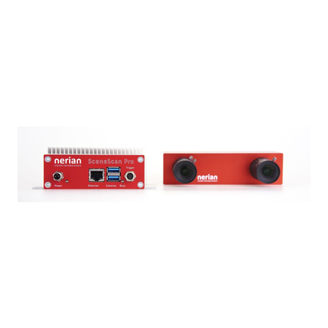
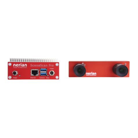
nerian Karmin2 User manual

Contents
1 Available Models 2
2 Specications 2
2.1 General Specications . . . . . . . . . . . . . . . . . . . . . . . 2
2.2 Dimensions and Mounting Holes . . . . . . . . . . . . . . . . . . 4
3 Trigger Port 4
4 Lenses 5
5 Camera Conguration 6
5.1 Pixel Binning and Bayer Pattern Downsampling . . . . . . . . . 6
5.2 Other Camera Settings . . . . . . . . . . . . . . . . . . . . . . . 6
5.2.1 Analog Control . . . . . . . . . . . . . . . . . . . . . . . 6
5.2.2 Image Format Control . . . . . . . . . . . . . . . . . . . 7
5.2.3 Acquisition Control . . . . . . . . . . . . . . . . . . . . . 7
6 Interfacing Karmin2 7
6.1 Connecting to SceneScan . . . . . . . . . . . . . . . . . . . . . . 7
6.2 ConnectingtoaPC......................... 8
7 Support 9
8 Warranty Information 9
1

1. AVAILABLE MODELS
1 Available Models
Karmin2 is available in two dierent baseline distances: 10 cm and 25 cm. The
10 cm model is intended for close-range measurements, while the 25 cm model
is intended for long-range measurements. The covered measurement range also
depends on the selected lenses and on the processed disparity range, which is
the image overlap range that is searched during image processing.
Both baseline distances are available with either monochrome or color im-
age sensors. When used in combination with SceneScan, the monochrome
versions can achieve higher image resolutions and frame rates. Using the
monochrome models is hence recommended if color information is not im-
portant for subsequent processing.
When using identical lenses and a constant disparity range, the 10 cm
models will have a lower minimum depth when compared to the 25 cm mod-
els. The depth error increases approximately quadratically with the measured
depth, starting at the minimum depth. Hence the 25 cm models will have a
lower depth error for all points that fall within its measurement range. If the
minimum depth of the 25 cm models is sucient, then these models should be
preferred over the 10 cm models. Detailed characteristics, including the mini-
mum depth, are available on the Karmin2 product page
1
for the most common
congurations.
2 Specications
2.1 General Specications
Camera modules
Basler daA1600-60um / daA1600-60uc
Sensor resolution
1600
×
1200 pixels
Sensor
e2v EV76C570
Sensor format
1/1.8"
Lens mount
C/CS-mount
Chroma
mono / color
Shutter
global shutter
Interface
USB 3.0
Trigger-input
4-pin Binder M8 connector
Stereo baseline distance
10 cm / 25 cm
Mounting bottom side
4
×
M3 threaded hole
1
×
1/4" UNC threaded hole (tripod mount)
Mounting top side
2
×
M3 threaded hole
Weight without lenses
280 g for 10 cm baseline
450 g for 25 cm baseline
Conformity
CE, FCC, RoHS
1
See: https://nerian.com/products/karmin2-3d-stereo-camera/
2

2. SPECIFICATIONS
-
144
-
100
-
294
-
250
?
6
41
?
6
41
(a)
-
40
-
40
?
6
35
?
6
35
(b)
-
24
?
6
24
-
74
?
6
24
(c)
Figure 1: (a) Dimensions and (b-c) placing of mounting holes for 10 cm and
25 cm versions of Karmin2. All measurements are provided in millimeters.
3

3. TRIGGER PORT
3
1
24
Pin Assignment
1 Trigger 0
2 Trigger 1
3 Ground
4 Reserved (Ground)
Figure 2: Pin assignment of trigger connector.
2.2 Dimensions and Mounting Holes
Dimensions of the available models are shown in Figures 1a and 1b. The
spacing of the available mounting holes is shown in Figures 1b for the top and
in Figure 1c for the bottom side of both versions. The measures in all gures
are provided in millimeters.
The top side features two threaded mounting holes with M3 metric threads.
The bottom side features four additional mounting holes with M3 threads, and
one mounting hole with a 1/4" UNC thread for use with tripods. The drill
depth of all mounting holes is 6 mm.
3 Trigger Port
The camera features a trigger port on the backside, which uses a male 4 pin
Binder 718/768 series connector. This connector matches the female trigger
connector on SceneScan and SceneScan Pro.
The following manufacturer part numbers correspond to matching connec-
tors, and should be used for custom trigger cables:
99 3376 00 04
Matching connector with solder termination, not shielded.
99 3376 100 04
Matching connector with screw termination, not shielded.
99 3376 500 04
Matching connector with cutting clamps termination, not
shielded.
99 3362 00 04
Matching connector with solder termination for 3.5 - 5 mm
2
cable cross section, shielded.
99 3362 25 04
Matching connector with solder termination for 2 - 3.5 mm
2
cable cross section, shielded.
99 3362 100 04
Matching connector with screw termination for 3.5 - 5 mm
2
cable cross section, shielded.
99 3362 100 04
Matching connector with screw termination for 6 - 8 mm
2
cable cross section, shielded.
The pin assignment of the trigger port is shown in Figure 2. There are two
trigger lines, named Trigger 0 and Trigger 1, which correspond to the equally
named trigger signals provided by SceneScan.
By default, Karmin2 is congured such that image acquisition only happens
4

4. LENSES
Table 1: Operating voltages for trigger port.
Voltage Description
4.2 VDC Absolute maximum voltage. Exceeding this voltage might
damage the camera and will void the warranty.
0 3.4 VDC Safe operating range
0 0.7 VDC Indicates a logical 0
1.8 3.4 VDC Indicates a logical 1
Table 2: Maximum allowed lens intrusion.
Mount type Lens rear diameter Maximum intrusion
CS-mount Less than 13.5 mm 7.8 mm
CS-mount More than 13.5 mm 6.0 mm
C-mount Less than 13.5 mm 12.8 mm (with 5 mm spacer ring)
C-mount More than 13.5 mm 11.0 mm (with 5 mm spacer ring)
upon a positive edge of Trigger 0. It is thus necessary to connect Karmin2 to
SceneScan's trigger port or to an equivalent trigger source. The trigger signal
will ensure that image acquisition of both cameras is synchronized, which is
necessary for processing the acquired image data.
The relevant voltage levels for the two trigger lines are listed in Table 1. The
absolute maximum voltage must not be exceeded in order to avoid damages
to the device.
4 Lenses
On the front-side, Karmin2 features two lens mounts for its two image sensors.
The lens mounts are compatible to the CS-mount standard. By using a 5 mm
spacer ring, it is possible to connect a C-mount lens. Karmin2 is shipped with
two spacer rings pre-mounted.
When mounting a lens, it is important that the lens doesn't intrude farther
than the maximum allowed lens intrusion. If the lens intrudes farther, it can
scratch the dust protection window. The maximum allowed intrusion depends
on the rear diameter of the lens. A narrow lens is allowed to intrude farther
than a wider lens. Table 2 provides a list of the allowed intrusions for C-mount
and CS-mount lenses with dierent diameters.
5

5. CAMERA CONFIGURATION
5 Camera Conguration
5.1 Pixel Binning and Bayer Pattern Downsampling
For many applications a high frame rate is more important than a high image
resolution. To cover such usage cases, the monochrome Karmin2 models can
be congured to use a
2×2
pixel binning. In this setting, four sensor pixels are
combined to form one image pixel. Using pixel binning allows the cameras to
operate at a higher frame rate. When used with SceneScan Pro, a maximum
frame rate of 40 fps is possible.
For the color models, SceneScan can perform a combined demosaicing and
down-sampling, which also results in the image width and height being halved.
This is the default operation mode when a color Karmin2 camera is connected
to SceneScan, or when a Bayer pattern pixel format is selected. The com-
bined demosaicing and down-sampling reduces artifacts from the Bayer pat-
tern, which improves the image processing quality.
Switching the camera conguration between full resolution and pixel bin-
ning / down-sampling mode will also aect the covered depth range, if the
disparity range is kept constant. A constant disparity range will cover a larger
percentage of an image that was acquired with active pixel binning, compared
to an image acquired at the native camera resolution. Hence, the disparity
range should be adjusted when changing the pixel binning conguration.
5.2 Other Camera Settings
The cameras provide a multitude of dierent settings that can be congured
when connected to SceneScan or SceneScan Pro. The available settings match
the ones available in the Basler dart daA1600-60um / daA1600-60uc camera
modules. For a full documentation of all settings, we hence recommend to
consult the documentation available by Basler
2
. The most common camera
settings are described in the following.
5.2.1 Analog Control
Gain:
Gain factor for the image sensor.
Gain auto:
Sets the mode for automatic gain control.
Black level:
Controls the analog black level as an absolute physical
value.
Gamma:
Controls the gamma correction of pixel intensity.
2
See https://www.baslerweb.com/en/support/downloads/document-downloads/basler-
dart-usb-3-0-users-manual/
6

6. INTERFACING KARMIN2
5.2.2 Image Format Control
Width:
Width in pixels of the selected Region-Of-Interest
(ROI).
Height:
Height in pixels of the selected ROI.
Oset X:
Horizontal image coordinate of the top-left corner of
the selected ROI. When congured through Scene-
Scan, this coordinate is measured relatively to the
image center.
Oset Y:
Vertical image coordinate of the top-left corner of the
selected ROI. When congured through SceneScan,
this coordinate is measured relatively to the image
center.
Binning horizontal:
Number of horizontal photosensitive cells that are
combined for one image pixel.
Binning vertical:
Number of vertical photosensitive cells that are com-
bined for one image pixel. There is a conditional de-
pendency to the
binning horizontal
parameter, which
has to be adjusted rst.
Pixel format:
Desired pixel encoding mode.
5.2.3 Acquisition Control
Exposure time:
Sets the exposure time.
Exposure auto:
Sets the mode for automatic exposure control.
Trigger selector:
Selects the trigger that shall be congured.
Trigger mode:
Controls if the selected trigger is active.
Trigger source:
Species the internal signal or physical input line to
use as the trigger source.
Trigger activation:
Species the activation mode of the trigger.
Exposure mode:
Sets the operation mode of the exposure.
6 Interfacing Karmin2
6.1 Connecting to SceneScan
Karmin2 is intended for use with the SceneScan or SceneScan Pro image pro-
cessing systems. Karmin2 should be connected with a Micro USB 3.0 cable to
one of SceneScan's USB ports. The Micro-USB-connector can be secure with
lock screws if an appropriate cable is used.
In addition to the USB connection, Karmin2 also requires a connection to
SceneScan's trigger port. A suitable trigger cable can be obtained from Nerian.
It is alternatively possible to use a trigger source other than SceneScan. In this
case please make sure that SceneScan is congured appropriately and that the
7

6. INTERFACING KARMIN2
Table 3: Supported trigger frequencies / frame rates.
Binning / SceneScan model Disparity range Max. feq.
Demosaicing
2×2
binning SceneScan 128 40 Hz
2×2
binning SceneScan Pro 256 20 Hz
Demosaicing SceneScan Pro 192 29 Hz
None SceneScan Pro 128 15 Hz
None SceneScan Pro 256 8 Hz
Figure 3: Karmin2 connected to SceneScan pro.
trigger source obeys to the voltage levels listed in Section 3. Figure 3 shows
Karmin2 connected to SceneScan Pro with a USB and trigger cable.
The trigger signal must provide an appropriate trigger frequency that can
be matched by the cameras and the selected SceneScan model. The possible
frequencies for dierent system congurations are listed in Table 3. In low-light
situations the desired frame rate might not be achieved if the sensor exposure
time is too high. In these cases, an appropriate exposure time upper limit
should be congured in the SceneScan camera settings.
SceneScan will load a suitable camera conguration for Karmin2 after the
initial connection. Please refer to the SceneScan / SceneScan Pro user manual
for information on the possible conguration options.
6.2 Connecting to a PC
When connected to a PC, Karmin2 will appear as two individual USB3 Vi-
sion cameras. Using Karmin2 with a PC is not ocially supported. This is
why an ocial API or example programs are not available. However, Karmin2
is compatible to Basler's Pylon camera API and software, which can be ob-
tained from the Basler website
3
. Please refer to Basler's documentation for
programming and using the cameras with a PC.
3
http://www.baslerweb.com/en/products/software
8

7. SUPPORT
7 Support
If you require support or if you have other inquiries that are related to this
product, please contact:
Nerian Vision GmbH
Zettachring 2
70567 Stuttgart
Germany
Phone: +49 711 2195 9414
Website: www.nerian.com
8 Warranty Information
The device is provided with a 2-year warranty according to German federal
law (BGB). Warranty is lost if the housing is opened by others than ocial
Nerian Vision Technologies service sta. In case of warranty please contact
our support sta.
9

Revision History
Revision History
Revision Date Author(s) Description
v1.1 July 13, 2019 KS Fixed mistakes and added color
support
v1.0 December 12, 2017 KS Initial revision
10
Table of contents
Other nerian Digital Camera manuals

