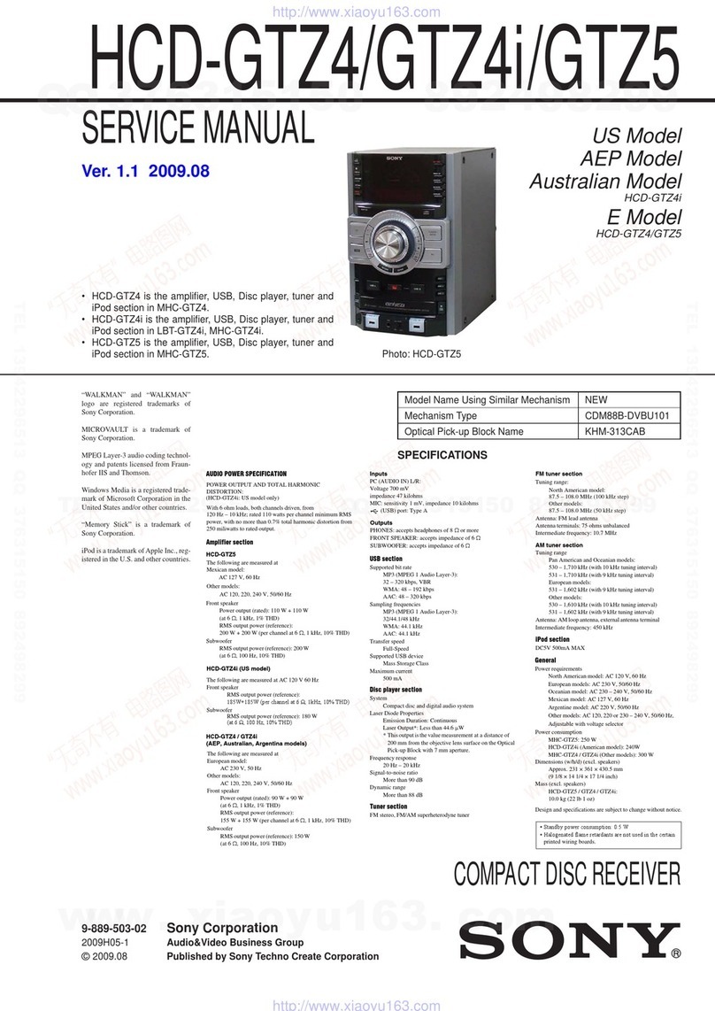
network 600 User manual

For
Service
Manuals
Contact
MAURITRON
TECHNICAL
SERVICES
8
Cherry
Tree
Rd,
Chinnor
Oxon
OX9
4QY
Tel:-
01844-351694
Fax:-
01844-352554
Email:-
SERVICE
MANUAL
for
service
technician
STEREO
MUSIC
CENTER
model
600
(Including
turntable
BSR
P-207
&
P-246)
SPECIFICATIONS
This
specifications
may
be
changed
for
improvement
of
performance
without
notice.
3
3
S
8
General
Semi-conductors..........
Sedeeeunede
41C,
56TR,
31
Diode,
7
LED
Usable
sensitivity
..................6-
LW:
8COz
V/m
Power
consumption.............-00.
80
W
(Max)
MW:
310
pV/m
WOIGKT
~
wicsiccossceccsdevciveces
Minette:
14.85
Kg
FM:
6.5
nV
Dimensions
..............
ceuebanenenes
656
(W)
x
299
(H}
x
463
(D)
mm
Image
rejection
..........2.cceeeeveeees
AM:
35
dB
FM:
30
dB
Audio
Section
S/N
GAtG
goccscdcaaveeci
Given:
AM:
40
dB
OUtPUt
POWER
........eecesscneeceecsees
TOW
+
10W
|
FM:
60
dB
T.HO.
vecdcsceccecececcececccsse.,
03%
FM
stereo
separation
............6-
30
dB
Ereasencyt
respons.
seceeeseeseee
BU™
25000
Hz
Hum
&
noise
(Aux)
ooo...
eee
60dB
Cassette
Section
input
sensitivity
(Aux)..............
I50mMV
|
Wow
&
Flutter
....--.ceecsceeeceeveeees
0.2%
(WRMS)
|
Bass
(10
KH)...
ccceeeeeeeeeeees
+8
dB
FF
&
ROW
ooucceeccccecccsenceeeecteeees
100sec
(C-60)
Treble
(10
KH2)
oo...
eeeeeeeees
+8
dB
Frequency
response
.............-...-
100~8000
Hz
|
SINatlO?
acumen:
45
dB
Tuner
Section
CrOSS
181K
o
ciecccdeos
desncevgarstotetisons
40
dB
Tuning
Range
............c.cccseece
eee
LW:
150~350
KHz
Erase
ratlo
..........cccccccsee
sen
ercconese
50
dB
MW:
515~
1650
KHz
Dolby
NR
effect
...........seeeeeeceee
9dB
FM:
87~109
MHz
Bias
freQUeNcy
.........seesceecreeeeeees
67
KHz

To
service
technician
This
service
manual
contains
detailed
service
information
for
Stereo
Music
center,
Model.
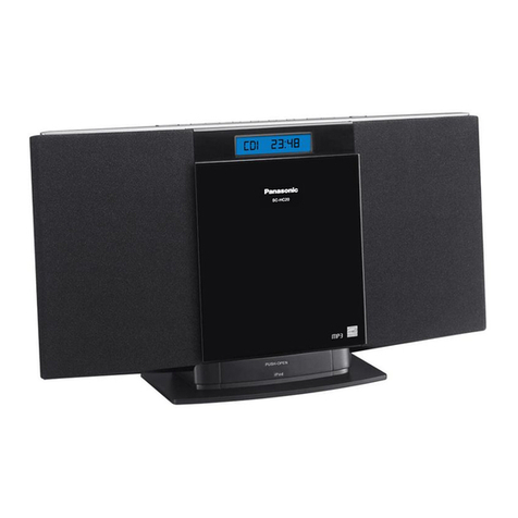
NW
600
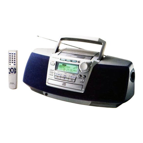
illustration
of
the
model
apperas
on
front
cover.
Please
give
attention
to
next
caution.
The
followings
are
the
safety
servicing
guidelines
for
all
audio
amplifiers
and
radio
receivers.
Service
work
should
be
performed
only
after
you
are
familiar
with
all
of
the
following
safety
guide.
To
do
otherwise
increases
the
risk
of
potential
hazards
and
injury
to
the
user.
3
Safety
guide
1.
Be
sure
that
all
components
are
positioned
in
such
a
way
to
avoid
possibility
‘of
adjacent
components
shorts.
This
especially
important
on
those
chassis
which
are
transported
to
and
from
the
repair
shop.
_
Always
replace
all
protective
devices
such
as
insulators
and
barriers
afte
working
on
a
receiver.
3.
Check
for
frayed
insulation
on
wires
including
the
AC-cord.
Also
check
across-the-line
com-
‘ponents
for
damage
and
replace
if
necessary.
4.
All
fuses
and
certain
resistors
and
capacitors
which
are
of
the
flameproof
type
must
be
re-
placed
with
exact
same
types
to
prevent
potential
fire
hazard.
5.
After
re-assembly
of
the
set
always
perform
an
AC-leakage
test
on
the
exposed
metallic
parts
of
the
cabinet
such
as
the
knobs,
antenna
terminal,
etc.
to
be
sure
the
set
is
safe
to
operate
without
danger
of
electrical
shock.
|
NO
To
order
repair
parts
Parts
order
must
contain,
|
SO
7
:
1.
Model
Number
—
found
on
front
cover
in
this
service
manual.
2.
Part
Number,
Description
and
Quantity.
_ |
”
(girs
eee
aerials
Contact’
|
| 7 _
MAURITRON
TECHNICAL
SERVICES
8
Cherry
Tree
Rd,
Chinnor
—
CONTENTS
Tet:
oiad
os
r004
Fax
G1844-52554
|
Email:-
Disassembly
instructions
..........---
ene,
tod
Se
eset
sy
are
ee
ree
be.
“2
Dial
cord
arrangement
.....
ee
Tere
ee
ee
ee
Peach
tees
Seca
esc
Sets
tle
deeeaee
3
Alignment
instructions
|
Tuner
alignment........
13
Ait
aah
noe
Ge
Maan
ea
ae
ne
eae
eee
re
3
Cassette
alignment
..........
sade
esacicie
hese
ah
east
a
eed
ae
evi
Aaa
ane
re
7
GiGUit
Had
2.<o
ne
cateeoehe
th
eewna
caesar
eeeeeode
Rus
abate
petit:
Angie:
WODNS
Electrical
parts
locations
..............
denser
White
tas
tee
pecs
anal
esl
Bh,
Be
(2.
1213
Wiring
diagram
..
0...
0.
ee
eee
eee
eee
ee
ee
ee
Seats
eee
14,15.
Exploded
view
for
Deck
mechanism
and
parts
list...
6...
eee
ee
tees
16.
17
©
Exploded
view
for
Turntable
BSR-P207
..........-.00008-
Se
at
agen
Ga
eee
18.
19
Exploded
view
for
Turntable
BSR-P246
..........
0000000
eee
eu
baeesaee
eed
20.
21
Parts
list
for
Turntable
BSR-P207
.........
or
pees
evade
tes
LAER
bass
22
Parts
list
for
Turntable
BSR-P246
0.0...
0...
eee eee
ee
ee
ees
Oe
ee
..23
Exploded
view
for
cabinet
..........
xe
aie
ee
eee
Serer
a
se
oe
..
24.25
Parts
list
for
cabeint
explodedview..
0.0.0...
0.0
cece
eee
eee
Daneae
en
sn
ara
26
Electrical
parts
list
.............
Pe
ee
eee
ee
wig
aipdaesaadaces
sa
aS
eae
ok
28

DISASSEMBLY
INSTRUCTIONS
For
Service
Manuals
Contact
MAURITRON
TECHNICAL
SERVICES
8
Cherry
Tree
Rd,
Chinnor
Oxon
OX9
4QY
| -
Tek:-
01844-351604
Fax:-
01844-352554
To
remove
Cassette
Ay
_
Emel
enquidectoriautvon.couk
Remove
the
screws
(2)
holding
the
cassette
Ay
and
lift
it
up.
To
remove
player
|
|
7 |
a)
Remove
the
screws
holding
the
Hole
cover
(1)
and
Pull
it
out
after
rotating
in
90
degrees
to
direction
of
arrows.
|
‘
b)
After
Changing
from
A
to
B
as
shown
in
Fig,
lift
up
the
player.
To
remove
main
chassis
ee
a)
Remove
the
screws
(3,4,5)
holding
the
cabinet
and
push
it
backward.
b)
Remove
the
screws
(6)
and
lift
up
the
main
chassis
as
shown
in
Fig.

DIAL
CORD
ARRANGEMENT
ae
ee
LA)
strRING
GUIDE
STRIN
!
fi
NG
GUIDE
(er
IT
(C.w)
DOUBLE
|
ROLLER
TUNING
SHAFT
4
TURNS(C.W)
PULLEY
,
Initiol
:
1
TURN
final:
{TURN
Set
the
dial
pointer
to
minimum
frequency
and
string
the
cord
by
following
the
number
sequence
_
order
as
shown
in
above
figure.
t
ALIGNMENT
INSTRUCTIONS
This
integrated
stereo
system
has
been
aligned.
at.the
factory
and
normally
will
not
require
further
adjustment.
|
|
As
a
result,
it
is
not
recommended
that
any
attempt
is
made
to
modificate
any
circuit.
If
any
parts
are
relaced
or
if
anyone
tampers
with
the
adjustments,
realignment
may
be
neces-
Sary.
|
Hii
secs
Manuals
Contact
:
| |
RON
TECHNICAL
SERVICES
Test
equipment
required
|
.
8
Cherry
Tree
Rd,
Chinnor
_
AM
IF
Sweep
generator
or
AM
IF
generating
scope.
: |
Oxon
OX9
4QY
|
Tel:-
01844-351694
Fax:-
01844-352554
.
Oscilloscope.
|
Email:-
VTVM
_
AM
SSG
(with
loop
ant.)
FM
IF
sweep
generator
or
FM
IF
generating
scope.
FM
SSG
(with
dummy
ant.)
_
| |
_
Frequency
counter,
> | | |
:
.
Stereo
modulator.
|
AnNOOAWN
>

TUNER
ALIGNMENT
Adjustment
and
Test
Points
EM
ANT
Ter.
1201
FM
IF
‘
L3
FM
ANT
L
Te
i.
2
R225
150
-
Tc102
|
peace
FM
OSC
[©]
mw
ant
R221
T™C103
TC101
_vP
i\WOSC
LW
ANT
R272
TP
|
|
©]
1202
FM
IF
7
MW
OSC
|
|@]r108
AM
IF
R123
T104
[SJawie
[O]
7101
wose
TP
|
T103
T102
MW
OSC
AM
IF
1C202
IC
201
sep.
adj.
-
R271
T.P
|
;
R222
Main
PWB
i
BALI
PRIS
AOC
et
pega
For
Service
Manuals
Contact
MAURITRON
TECHNICAL
SERVICES
8
Cherry
Tree
Rd,
Chinnor
Oxon
OX9
4QY
Tel:-
01844-351694
Fax:-
01844-352554
Email:-
%
%
&
%
i

ren
ere
SF
2
ee
ee
oe
ee
eee
ee
ee
~~
an
eee
eee
|
EO
ew
ST
Se
Pe
Se
ee
‘
t
ri
=
J
s
{
bg
ee
AZL—-NS
=—
fe
ew
ae
ee]
ee
oe
aouepsedwy
INndINO
OSS
WS:
Hy
On
i
i
i
’
4
a
i
i
é
(
Ls
dec:
emi
ahe
ew
ae
ee,
ene
ee
ae
om
oe
oe
ae
ow
ot
Pa
ge
ee,
ee
a
EER
Re
eee
|
#3.
3BOUd
|
WJ.
3808d
YOLIG
YIM
7]
40
Y
O@l8IS
YIM
|POG
2yNau]
"(pow
yo}Id
‘payndut
peindul
JOU
JaUUEYD
e
JO
jeuBis
07
suns
Gr.
BG014
}Ou
Og
O}
%OL
“Qns
pue
ulew
%06
WNWIUIWW
JO}
ISNipy
|
indjNO
jauueYd
e
JO
‘ZH
LL)
ZHW
86
Joes0Ucb
JOPEIBUBS)
jourwsal
JS
jeuBis
Ogseys
pue
HSS
WH
jeuluise
|
jeuluse
|
wnding
3ndu|
:
|
|
LYVHO
LNSWNOITV
X31d1LINW
WS
“ebueyos
winwiuliu
JO}
(q)
‘(2)-—
wal
aaoge
ey}
yeeday
ho
|
WALA
pue
(ud}eIAEg
WWIdg
Aouenbe
4
|
wew
snipy
Bures
ieiG
B
WUSUINI
SU
(L@ZH)
LZZY
JO
ae
G,,
OQOsSg
jeUIWE
|
jeut
ue}
Ans
ee
Rain
|
“uied
jeuBis
02
sun,
indinoO
Indino
Indu}
HW
.
4
anes
anas
is
wath
40321885
sexeadS
yy
WALA
pue
(UdIIEIASQ
ZHA
BZ
‘ZHOOP)
ZHW
06
OSS
WA
‘aBueyos
wnwiultu
JO}
(q)
‘(&)-Z
wal!
BAOgE
Gy)
JeedeyY
ysIO
|
|
WALA
(Z7ZY)
LZ?
("843
SeYyBI})
Gs,
PQOLd
JOUsLUse
f
pue
(u01BIAEG
-uleb
BSIMADOjO
Ayn
InNdINO
Indino
(ZH
S'S?
‘ZHOOP)
|
wnwixew
Jos
isnipy
Bueb
Buiun
JOEIOUAL)
_sayeeds
ZHW
601
OSS
Wa
("845
3S8M07)
(L7ZY)
LZZUY
WALA
“ETNISO
@SIM¥D0]9
Ge,
OQIO¢E
40
jeu
|
pue
(uo!
eIABG
W-
Zz
|
"uieb
Ss)
-48,UNOD
Atny
Indino
indinD
ZHAG
ZZ?
ZHOOY)
winwwixei
JO}
IsN{py
—Bues
Buiuny
JO}OIBUaS
Jaxeads.
ZHW
28
OSS
WS
("845.4
SAMO)
Buryeseueb
4)
WH
BSIMHADOID
ad.
8QOld
JO
BdODSO}|I19SO
BAIND
..S,,
-S81UNOD
Ajjns
indino
pue
10{e1BUBS)
Bue
Buruny
J078JBUSS
dI-Wa
daems
4!
Wd
peusuise
|
peusue
f
indino
ynduj
.
:
| |
,
LYVHD
LNSWNDITV
WS
+UlOd
zueLUISNI
ply
Asuenbei4
1M
PUBLUNAZSUY
esoding
BuIneS
181G

old
jeuBis
0)
oun,
|
"u1e6
Wnwixew
JO}
Isnipy
(109
"lu
AAT)
|
Lot)
JeuBIS
OJ
BUN
|
(21)
IS84BIH)
BSIMADO}O
Ayn
EOLDL
6ue6
Gulun,
"uieb
WNUWHXeLU
JO}
IsNipy
(‘A1f
1S8MO})
BSIMAIOID
JBJUNOD
ALN
Buec
Buruny
|
"web
ZOLOL
LUNLWIXeW
JO}
IsN[pY
yeubis
03
oun
({109
|
“WY
MW)
LOL
(84)
3S8461}4)
BSIMHADOIS
Ajjny
Buen-Bujuny
*ureb
uNnw)yxew
JO}
Isn[py
{bai}
IseMmo'y)
SIM
YDO]>-4J8UNO’)
Aung
Gued-Buyuny
("843
YSBMO07)
BSIMAOOjD-JBLUNOD
AqIN
Sueb-Burun,
WO,
wueWwIsnipYy
esoding
BuizeS
(819
wW7,,
8QOsd
Awwin
|
‘aBueyo
WNWwiui
sO}
(Q)
'(2)-G
WAI!
aAOge
aU)
Yeaday
WALA
pue
(POW
%OF
“ZHOOP)
ZH
OLE
OSS
WV
(EZ1L)
andino
10398339
"UY
SUON
40
*J8}
yaubew
saem
WALA
Pue
INdINO
YS
WV
(POW
%0E€
‘ZHOO?r)
ZHA
OO!
OSS
WV
‘abueyd
wNwiuiw
JO}
(Q)
‘(2)-p
wai!
eaoge
ey)
leedey
WALA
pue
|
{POW
%0E
‘ZHOOr)
(ETL
Yd)
nding
40}93}8q
eiiacenaeaad
“BI
HOSO
v
Buoy
JO
“JOE
“UY
WALA
pue
indino
jouBbew
saem
(POW
90€
‘ZHOOP)
dS
WV
2H»
OVl
OSS
WV
©
aBueUo
LuNuiulW
40}
(Q)
“(8)-E
way
anoge
OU}
jeadey
4
|
|
WALA
pue
oO
é
(EZb
wy)
wnding
is
saree
40}99128q
uy
a
aUON
JO
jeuttusal
youBew
_
OSS
WY
:
—
INdING
)
SACM
WALA
pee
Jaxeads
WV
(POW
%0E
‘ZHOOr)
2H»
009
|
OSS
WV
"eBueyd
winwiulu
JO¥
(Q)
‘(€)-Z
Way!
saoge
eu
leadey
WALA
pue
(PIOW
%OE
"2ZHOOY)
ZH>
OSOL
OSSWNV
40}
(EZLW)
ANAdING
-BI}J9SO
Suon)
J109918Q)
“uy
MW
JO
Jeuluual}
yeubew-aacem
WALA
Ppue
INdINGO
4exeedS
WY
(POW
%OE
‘ZHOOr)
ZHA
SLS
OSS
WV
edoos
Bujjeseueb
—
-NdINO
|
(€ZLY)
wNdINO
dl
Wi
40
‘edosso]|!95¢Q
ArWwv
JOWRIBUB
|
40}93798G
Pue
JOesaUaS
|
Gsams
41
WV
{eUpuse
|
jeujuuel
,
Aouenbes4
3ndyno
indu}
;
Us8}
|
g
}UeLUNIISU|
LYVHO
LNAaWNOIIV
WV

CASSETTE
ALIGNMENT
Tape
head
and
capstan
cleaning
1.
Periodically
clean
the
tape
head,
capstan
drive
shaft
and
other
tape
handling
surfaces
to
insure
|
proper
tape
handling
and
optimum
frequency
response.
2.
Use
a
cotton
swab
lipped
in
head
cleaner
or
denatured
alcohol
to
clean
all
tape
handling
sur-
faces.
Wipe
dry.
Tape
head
demagnetization
When
servicing
tape
unit,
do
not
use
magnetized
screwdrivers
or
wrenches
near
the
tape
head
since
they
can
magnetize
the
head.
A
magnetized
head
will
result
in
loss
of
high
frequency
response
and
increased
noise.
Head
adjustment
Head
adjustment
is
normally
required
when
the
head
is
replaced
or
f
poor
high
frequency
response.
Adjustment
and
test
points
VR654
(L)
(x)
Level
meter
adj.
Dolby
level
adj
vreo4in)
(X)
®)
Q
VR651~—s
vR601
(L)
(R)-
E
si
TA
(R)
IC
651
R
T601(R)
19KHz
trap
adj.
Rec.
sens.
adj.
|
Test}
|
VR653
(L)
VR603
(R)
Cassette
PWB
or
cases
of
cross-talk
and
P51
—
P53
T602
(R)
Bias
trap
adj.
T652
(L)
P,56
OC)
P.55
OC)
Bias,
current
adj.
«)
@
VR605(R)
VRES5S
(uy
T6117
ec.
freq.
adj.
)
|
For
Service
Manuals
Contact
MAURITRON
TECHNICAL
SERVICES
8
Cherry
Tree
Rd,
Chinnor
Oxon
OX9
4QY
Tel:-
01
844-351694
Fax:-
01844-352554
Email:-

ALIGNMENT
CHART
Step
|
tem
—
|
Condition
|
Input
signal
Procedure
Output
test
point
Remarks
2
—
Adjust
the
semi-
fixed
resistors
VR601
(R),
VR651
(L)
adjustment
R/P
head
Tape
selector
|
MTT-114
1)
Playback
the
T4(R),
T2(L)
by
|
VTVM
should
adjustment
|
switch;
normal
|
(10Khz,-10dB)
|
test
tape
VTVM
read
maximum
Dolby
NR
|
2)
Adjust
the
:
|
output.
The
switch:
off
azimuth
adjusting
:
difference
between
screw.
.
R
and
L
shouid
be
within
2dB.
Dolby
MTT
150
Playback
the
|T4
(R),
T2(L)
bY
|
VTVM
should
2
Level
(400Hz,
OdB)
test
tape
VTVM
|
read
580
mV.
Level
meter
MTT-150
1)
fines
the
Level
meter
Level
meter
adjustment
(400Hz,
OdB)
|
9)
Adjust
the
semi-
indication
should
indicate
fixed
resistors
_
Dolby
mark
VR604
(R)
VR654
(L)
(+3VU)
Erase
head
Frequency
/
counter
should
Bias
Tape
selector
Blank
tape
|
1)
Insert
blank
tape
frequency
switch
:normal
and
activate.
(P55,
P56)
adjustment
RECORD
mode.
|
by
frequency
read
67
KHz.
2)
Adjust
oscillator
|
counter
coil
T611.
|
1)
Insert
blank
tape
Blank
tape
VTVM
should
Bias
trap
Tape
selector
adjustment
switch:
normal
—
and
activate
read
minimum
|
RECORD
Mode.
TP.
P53
(R),
2)
Adjust
trap
coil
TP.
P51
(L)
—
T602
(RA),
by
VTVM
T652
(L).
19kHz
trap
19KHzt2Hz
Set
the
deck
in
T4
(R)
VTVM
should
adjustment
-10dB
audio
RECORD
mode
|
T2(L)
read
minium
—
|
signal
thru
and apply
the
by
VTVM
aux
jack.
signal
2)
Adjust
19kHz
trap
coil
T601
(R),
T651
(LI,
Insert
blank
tape
and
activate
RECORD
mode.
Adjust
the
semi-
fixed
resistors
VR605
(R),
VR655
(L)
Record
the
signal
on
MTT-501,
Rewind
and
play-
back
the
recorded
tape
Adjust
the
semi-
fixed
resistors,
VR603
(R),
VR653
(L).
~=——
VTVM
should
read
4mV.
TP.
P53
(R)
TP,
P51
(L)
by
VTVM
Tape
selector
switch:
normal
Bias
current
adjustment
|
Blank
tape
2
~—e
VTVM
shouid
read
580
mV
1kHz
audio
signal
thru
au
jack.
.
*
Tape
selector
swi
tch
‘normal
Recording
sensitivity
adjustment
2
a
3
—
For
Service
Manuals
Contact
MAURITRON
TECHNICAL
SERVICES
8
Cherry
Tree
Rd,
Chinnor
Oxon
OX9
4QY
Tel:-
01844-351694
Fax:-
01844-352554
Email:-
“Set
Fe
2
ha
OT
PP
CP
TIF
t~“n.
IPF
™Irdtiszat_aeztis
=
~
2.
waz
aE
*
ew
YY
er
Pwrows
rerrm
¢
Ry
bk.
1.
T7aITs
a
i

Equipment
Arrangement
for
Cassette
Alignment
Step
1.2
P/B
Head
ib
v
MTT-114
(Step
1)
MTT-150
(Step
2)
Step
4.
REC
Head
Blank
Tape
Step
5.7
REC
Head
Blank
Tape
Step
6.8
AUDIO
signal
Gen.
19KHz+2Hz,
-10dB
(Step
6)
1KHz
{Step
8)
UNDER
SERVICE
©?
TP
(T4,
T2)
SET
|
UNDER
,
©
SERVICE
VTVM
TP
(P55,
P56)
SET
Freq.
counter.
TP
(P53.
P51)
SET
UNDER
:
&
SERVICE
| |
e
VTVM
TP
(T4,
T2)
SET
|
UNDER
.
SERVICE
VTVM
-
For
Service
Manuals
Contact
MAURITRON
TECHNICAL
SERVICES
8
Cherry
Tree
Rd,
Chinnor
Oxon
OX9
4QY
Tel:-
01844-351694
Fax:-
01844-52554
Email:-

189
eocet
1990
#03
we
vw
tues
£299,
|
OMT
S
ae
:
a
eeu
=
|
radu
Sy
leew
91/1
+]
eG
seeo
|
fe
$4
>
.
€
bos
a'e's
1/0!
xol
a
‘
=
i
49
Gd
t
ais
2901
Scent
z
Gu
ey
4
3
.
2
'
Can
a
cess
resid
:
36
oye
ws
|
;
(3dar
wow)
:
‘
Pa
:
wove
ota
t
—
i)
te
oot
4fecooo
[ve
*
4
=
»
O8@
1298
Ss
985
eid
>
BOysa
tascooeh
-
|
gs
:
;
HEE
?
a
4
~~
6if/ol
ae
0
t3}
a
Lf}
_
gov
ak
a
|
.
|
;
3°
fot
ee
Bp
F4
Soreau
t9O
Dt
=
o-
“=
—
sa
ee
ee
*
:
Civ
San
odie
10f9
e
Of
HL
|
</
pe
HOSS
wee
€OVD
1'OC8
Zocy
4
ONOHG
421
lety
Sdw
este
OF
UL
die
iSt9
iO
Weioo
xoss
|
Wee
Sed
Iscy
26¢4u
x2’o
«60S
A
9'0
SOfcu
2ots
Oe
WIL...
©
|
(2d0)
4.0
advi
J
|
eer
a
sziu
~290
wad
89151
wewe
aon
of
al
e010
tms000
3219
O08
&
ace
4g
Es
pe
Clty
ly
KEId
Site
vou’
8:08
-pee
S209-6¢8
g-nsesl¢!
1
1024
re)
7
oO
yroouoquNeWw@seyinbue
-yew3
WVYHOVIG
LINDY!
PSSCSE-PHBLO
--XB4
PE91SE-Pr810
-“9L
AO¥r
6XO
UOXO
JOULIYD
‘Py
9011
AUeYD
g
SIOAYAS
TWOINHOSL
NOULIENVA
yoRuoy
syenuepy
ede
404

xos
a0cs
i
ims
26Gu
1SS9
Oy
pastes
me]
ET
|
|
PEDISEDE
©
—J
1
a
eee
4
|
9OGH
lash
ol
Mu
a
a)
oi
Or€ion
20291
_
fy
208-859
Gi29
a
Sn
}
a>
GOza
»
Oe
ee
A
Ay
nai
{mKTOTO
1229
way,
L—_I
MAL
DION!
CO)
omass
(%
)
F¥
/V
oad
'
roo
uaRUNeWeoseuinbua
-!pews
YSSCSE-PB
LO
--XB4
¥691S6-prBL0
-JO,
ADP
6XO
UOxO
JOUUIYD
‘Py
ee,
AueUD
g
SAOIAUSS
TWOINHOSL
NOWLILAVAN
PRUOD
syenuey
ad1ANas
104

Mm
ZONVNNORSd
630
0
OuUvVGHOS
SiMl
»
WA
FBNNVWHO
1437
€
TRA
wOLIDVdy?
Tv
2
“WA
JONWISS3N
Ty
|
ee
EE
is
SS
Since
<i
giziss
£990
£
eo
Rot
zee¥
|
—
as
98!
uG@e
dda

For
Service
Manuals
Contact
8
Cherry
Tree
Rd,
Chinnor
Oxon
OX9
4QY
’
Tel:-
01844-351694
Fax:-
01844-352554
MAURITRON
TECHNICAL
SERVICES
aNOHa
OWaH
Email:-
_
Wanv2a
§
au:
dvi
wuan(E
anv
wainioa
(EL)
wO10R
HAAW
el
XW

~~
Core
eI.
4
ae,
Soy
Ao
Saal
}
<
BE
ai
Sa
bo
—;
TE
RED
wae
,
;
Z
\
weer
seme
fa,
LUE
ee
Pee
ro
Soe
ae
Eco

AO
cp
oe
near
ee
mene
eet
A
ra
Lem
ae
eed
Sand
Heetoniae
a
—.
—
Ay
Paty
ene
i
:
i
a
oe
ee
ee
ee
ee
eee
‘
WVYDVIG
ONIHIM
adAl
AG
OOIW
MOLOM
LE9
BAL
VOM
O-E9G)
AV
TwNIWe
a2
[
——
ete
ey
cm
ee
ee
eee
ee
ee
@Ad
183
Ovan
“3
Fy
%.
Wate
119
‘el
CL:
eas}
‘|
Wwixwo5
#20
GY
140(L16,
LO
G~
Ki4B)
Dam
rete
ei
me
ee
eee
ee
oe
wdAL
ANY
For
Service
Manuals
Contact
MAURITRON
TECHNICAL
SERVICES
8
Cherry
Tree
Rd,
Chinnor
Oxon
OX9
4QY
Tel:-
01844-351694
Fax:-
01844-352554
Email:-
Gad
NVR
MS
MIAOd
~
yoes
-
11S
(AS
NBMOd
OL
A
we
Paes
eee
eee
ren
le
a
ee
oe
{3090-"201
*217}009
wO
8c@
TL
ZTUQQI
Ns
62s
ut
{asiG-
9G)
fau)
fe
TAN
=
waa
0
AL

81s
fh
rr
g
3
|
353
-
O@ea
[SCREW
ENEDEC!
[S|
sis
~0208
[screw
Speciac
[n=
090
[wasen
[7
[347
cara
[sro
WOE
[a
[ee
007A
[ant
sree,
[a
[se
~3i7a
[HOLOER
act]
oe
Cert
nem
ALARM
I
ating:
EMR
RS
OTIS
MMMM
RAED
So
stiien
i
.
[3
]333
-
0458
|
LEVER
CLUTCH
|
32
|384-coza
[wasWER
sToPPWa
1111
|
oO
by
ec
MODEL
:
D-02S
oP
sree
20
_
\
\e
~
eee
ee
ee
et
+
A
~
:
cS
{
No}
part
wo
|
NO
|
pescrenon
|
aban
|
|
383
-o22a|ScREW
SPE
|
[75
[350
~O1G
(WASHER
spec.
fi
tili
[a
|
[We
laae
-oezaispraa
ttf
lada
[tr
[ese
-ozve[wut
seem
(i
filit
il
76
|
357
~
Oa
[ie
GlurcH
ay
fifi
lids!
a|
E
Deimcac
BeoaG
£
i
eelelais|a
Bagi
zlsigiale
il
BEER
FEEEDEF
FI
&
ua
‘
B
QOOOGESEoOoErs
102
nao
[03/477
~
Coda
[RuaER
woTOR
"TS
TS]
373)
Ji)
[oe[See
=
Osea
Twasner
“speci
[51313]
3)
[OS
|
mec
534
[SCREW
M2.8x8”
[3[3]
3/3]
<u
COR
OY
WG
I
Be
:
sateee
-
ee
ae
et
ee
pee
mee
:
sistant
ie
Sea
=
Fe
eget
int
ae
tee
tpg
San
oma
SN
TRC
Nettie
manne
ott
aatimd
te
nee
mE
ee
cae
a
meedepandinee
Je
a
es
ane
Ni
Mhe
ae
nea
20
3
IRA
ee
RES
HMR
NRE
en
Base
bomi
te
bead
Cpl
hae
eR
RM
OE
aes
we
in
See
7
ve
Ma,
a
oh
ect
4SI7
SLUYVd
GNV
WSINVHOSW
4030
YO4
M3IA
G3d01dx4

EXPLODED
VIEW
FOR
TURNTABLE
BSR-P207
H
i
7
i
i
Hi
Oxon
OX9
4QY
Tel:-
01844-351694
Fax:-
01844-352554
Email:-
For
Service
Manuals
Contact
MAURITRON
TECHNICAL
SERVICES
8
Cherry
Tree
Rd,
Chinnor
te
\\S
Ss)
Y
Oy
rf
a
o1
|
©
)
ies
-
19
—


RE
(2
BI14614
A102110
0114616
A111913
A102110
A111999
B114636
A102109
A102595
A104189
B114639
A106090
A106089
A102166
A106510
A102126
A102616
A106206
A106510
A102126
A106090
A106089
A114654
A115011
A106015
B114542
B114544
B108181
wr
so
PARTS
LIST
FOR
TURNTABLE
BSR-P207
Description
Turntable
Adaptor
Circlip
Turntable
Moulding
Circlip
Circlip
Actuating
Pawl
Assembly
Cam
Gear
Riveting
Assembly
Circlip
Washer
Transit
Screw
Mainplate
Assembly
Spring
(Unit
Mounting)
Spring
Cup
7
Retaining
Cup
Clip
Screw
type
B
No.
6x
6.5
Rec.
Pan
Hd.(2
off)
Solder
Tag
(2
off)
Phono
Socket
Tag
Mounting
Strip
ScrewlypeB
No.
6x
6.5
Rec.
PanHd.
Solder
Tag
|
Spring
(Unit
Mounting)
Spring
Cup
Quadrant
Assembly
150mm
of
13
P.V.C.
Sleeving
Retaining
Strip
120v
Miniature
Switch
Assembly
240v
Miniature
Switch
Assembly
Switch
Body
=
.
—
#2'
ial
A106129
A100762
A101646
A102181
A106510
A102128
A106034
A105831
B106021
1A102109
A105619
B110364
A105965
)}A105824
A101620
A101623
A101620
A100762
A102128
A108589
A105267
B114612
A106510
A102166
A106512
A106089
4106090
Bi)
Ag
Description
Switch
Lever
Circlip
(3
off)
Washer
(Soff)
Rubber
Mounting
(3
off)
Two
Pole
Motor
Assembly
(T.P.8)
Screw
type
B
No.6x
6.5Rec.
Pan
Hd.
Circlip
Speed
Change
Bracket
Spring
(Raising
Spindle)
Speed
Change
Arm
Circlip
Adjusting
Screw
Raising
Cam
Jockey
Arm
Riveting
Assembly
Spring
(Jockey
Pulley)
Jockey
Pulley
Spinde
Washer
Jockey
Pulley
Assembly
Jockey
Pulley
Spindle
Washer
Circlip
Circlip
Raising
Spindle
Screw
type
B.T.4-24x
8
Rec.
PanHd.
On-Off
Slide
|
Screw
type
B
No.
6x
6.5Rec.
Pan
Hd.(2off)
Retaining
Clip
Screw
type
B.T.4-24x
16
Rec.
Pan
Hd.
Spring
Cup
Spring(Unit
Mounting)
win
n-OfD
Table of contents

