NEW SUNRISE NVR-1000 User manual

NVR-1000 OM.E 20130216-002
NVR-1000
VHF RADIOTELEPHONE
USER’S MANUAL
NEW SUNRISE

NVR-1000 MANUAL
NVR-1000 OM.E 20130216-002
NOTICE TO USERS
-Thanks for your purchasing this product VHF radio telephone.
-The copyright of this manual is owned by the manufacturer, NEW
SUNRISE CO., LTD (NSR). Prior written permission is required for copying
or reproducing the manual or part of the manual.
-Software version in your product may be some different from that
described as in this manual. Such difference will not affect the performance
of the product. NSR reserves the right of continuous improvement on
products both in software and in hardware without any prior notice.
-NSR will assume no responsibility for the damage caused by improper use
or modification of the product or claims of loss of profit by a third party.
-Please read this manual carefully to ensure proper use before installation
and use of the NVR-1000.
-Please keep the manual for your future reference.

NVR-1000 MANUAL
NVR-1000 OM.E 20130216-002
Some Frequently Asked Questions
How to check out own ship’s MMSI?
Own ship’s MMSI will show up shortly when the NVR-1000 is powered on.
You may also check out the MMSI in “DIAGNOSTICS”.
How to setup own ship’s MMSI?
The MMSI can be entered in SUPERVISION----MMSI SETUP. The password is
needed for the setting.
How to send a TEST call to other station?
Send a test call to other station in DSC MENU----SAFETY CALL----TEST. Wait for
the reply from the called station.
How to reply TEST call from other stations?
When AUTOMATIC ACK is set as YES in MENU----OTHER SETUP, the NVR-1000
will automatically reply to test call from other stations.
NVR-1000 MANUAL
NVR-1000 OM.E 20130216-002
SAFETY INSTRUCTIONS for the operator
Warning
Keep away from heat source or direct sunshine.
Prohibition
Don’t open the equipment. Only qualified personnel should
work inside the equipment. Don’t disassemble or try to modify
the equipment.
Dangerous
Turn off the power immediately when smoke or fire is emitted.
SAFETY INSTRUCTIONS for the installer
Warning
Connect the earthing cord to ship’s body.
Observe the compass safe distance to prevent deviation of
an onboard magnetic compass.
Prohibited
Don’t open the equipment unless you have fully understood
the structure and circuits of the equipment.
Only qualified personnel should work inside the equipment.
Don’t disassemble or try to modify the equipment.
Dangerous
Turn off the power at power distribution board before
installation.

NVR-1000 MANUAL
NVR-1000 OM.E 20130216-002
Table of Contents
1. OVERVIEW...........................................................................................................1
2. CONFIGURATIONS .............................................................................................2
2.1 SYSTEM CONFIGURATIONS ............................................................................2
2.2 SUPPLY SCOPE.....................................................................................................2
3. SPECIFICATIONS................................................................................................3
3.1 GENERAL SPECIFICATIONS.............................................................................3
3.2 TRANSMITTER.....................................................................................................3
3.3 RECEIVER.............................................................................................................3
3.4 DSC FUNCTION....................................................................................................4
3.5 DEDICATED DSC RECEIVER (WKR) ...........................................................4
4. STARTING SYSTEM ...........................................................................................5
4.1 POWER ON...........................................................................................................5
4.2 POWER OFF .........................................................................................................5
5. BASIC OPERATION............................................................................................6
5.1 KEYS ON THE FRONT PANEL .......................................................................6
5.2 KEY DESCRIPTIONS...........................................................................................6
5.3 BASIC OPERATION.............................................................................................7
6. INITIAL SETUP....................................................................................................8
6.1 CLOCK SETUP......................................................................................................8
6.2 POSITION SETUP .................................................................................................8
6.3 OTHERS SETUP....................................................................................................9
6.4 DIAGNOSTICS......................................................................................................9
6.5 SUPERVISION.....................................................................................................10
7. DSC CALLS.......................................................................................................12
7.1 MAKE A DSC CALL.........................................................................................12
7.1.1 DISTRESS CALL.....................................................................................12
7.1.2 URGENCY CALL .....................................................................................14
7.1.3 SAFETY CALL .........................................................................................16
7.1.4 ROUTINE CALL.......................................................................................17
7.1.5 SEMI / AUTO VHF ...................................................................................19

NVR-1000 MANUAL
NVR-1000 OM.E 20130216-002
7.1.6 TRANSMIT A STORED DSC MESSAGE ...........................................20
7.2 RECEIVE A DSC CALL...................................................................................20
7.3.1 DISTRESS CALL......................................................................................21
7.3.2 URGENCY CALL .....................................................................................21
7.3.3 SAFETY CALL .........................................................................................22
7.3.4 ROUTINE CALL.......................................................................................22
7.3.5 SEMI / AUTO VHF ...................................................................................22
8. INSTALLATION..................................................................................................23
8.1 VHF ANTENNA INSTALLATION......................................................................23
8.2 TRANSCEIVER INSTALLATION......................................................................23
8.3 CONNECTION.....................................................................................................23
8.3.1 POWER SUPPLY ......................................................................................23
8.3.2 GPS DATA INPUT.....................................................................................24
8.3.3 CONNECT TO PRINTER .........................................................................24
8.3.4 CONNECT TO (S)VDR.............................................................................24
Appendix Ⅰ. CHANNEL TABLE .............................................................................25
ITU Channel Table.........................................................................................................25
USA Channel Table........................................................................................................26
CAN Cannel Table.........................................................................................................27
Private Channel (simplex)..............................................................................................28
WX (Weather) Channel Table.......................................................................................29
Appendix Ⅱ. INSTALLATION DRAWINGS............................................................30

NVR-1000 MANUAL
NVR-1000 OM.E 20130216-002
1
1. OVERVIEW
NVR-1000 is a ship borne radiotelephone equipment on VHF FM and designed for
marine mobile service which provides function of VHF radiotelephone and digital
selective calling. It is to be met by provision of GMDSS required as 1988 GMDSS
amendments to SOLAS 1974.
It contains a VHF radio transceiver and a digital selective calling system and a dedicated
digital selective calling receiver to comply with the ITU Radio Regulations, the
performance standards developed by IMO and ITU.
Main features are as follows:
Channels
International Standard Channel (ITU), America Channel (USA),
Canada Channel (CAN), Weather Channel (WX), Private Channel
(PRV)
RF output
25W (HIGH) / 1W (LOW)
Dual watching
Watching channel 16 and other channels simultaneously is available.
Channel scan
Channels are scanned to sample any signal to be received.
DSC
A dedicated DSC receiver is included.
NVR-1000 MANUAL
NVR-1000 OM.E 20130216-002
2
2. CONFIGURATIONS
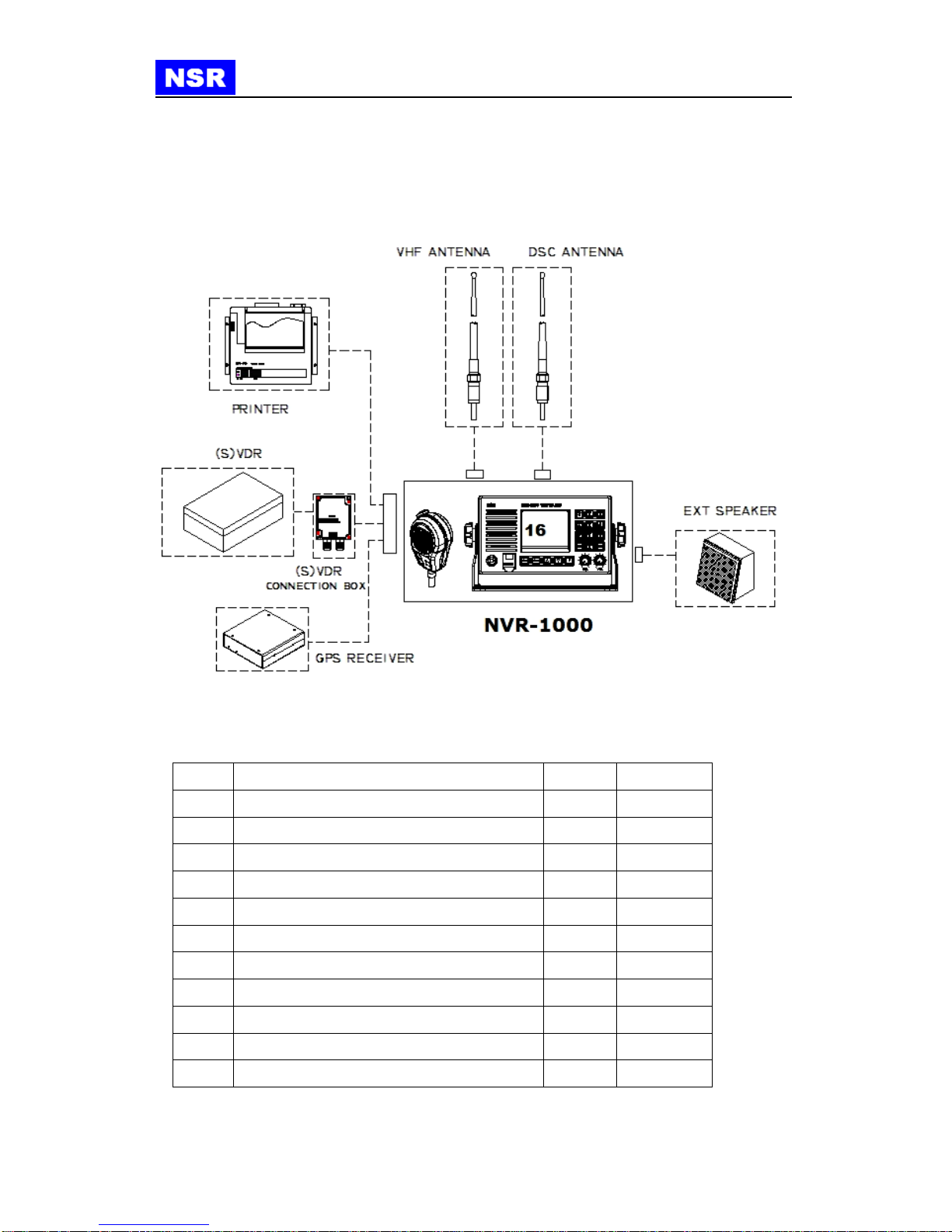
2.1 SYSTEM CONFIGURATIONS
The below figure is for the configurations of the equipment.
2.2 SUPPLY SCOPE
No.
ITEM
Q’TY
REMARKS
Standard
1
NVR-1000 VHF RADIOTELEPHONE
1
2
NVR-1030H MICROPHONE
1
3
FITTING MATERIALS
1
4
USER’S MANUAL
1
Optional
1
VHF ANTENNA
2
2
THERMAL PRINTER
1
NPT-100
3
VDR CONNECTION KIT
1
NVC100
4
EXTERNAL SPEAKER
1
5
POWER SUPPLY UNIT
1
13.5V/10A
NVR-1000 MANUAL
NVR-1000 OM.E 20130216-002
3
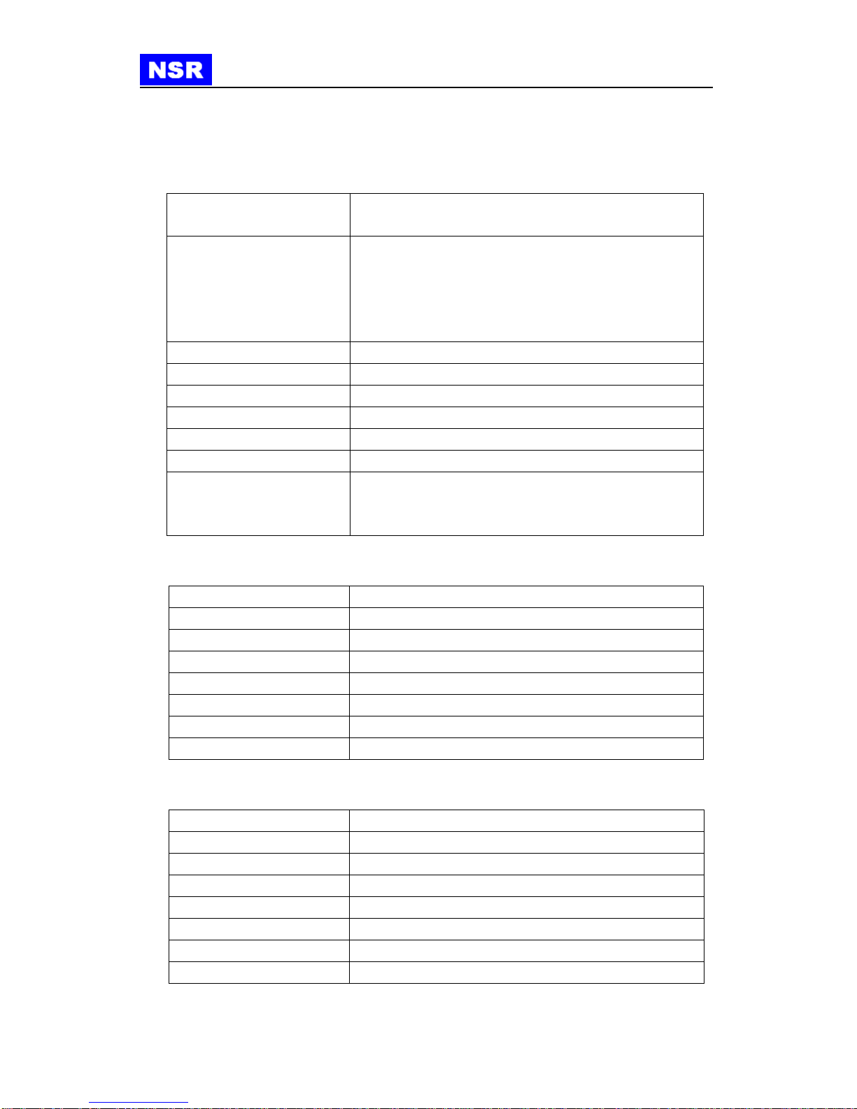
3. SPECIFICATIONS
3.1 GENERAL SPECIFICATIONS
3.2 TRANSMITTER
Output power
25W (High), 1W (Low)
Maximum frequency shift
≤±5kHz
Modulation type
FM (pre-emphasis 6dB/octave)
Frequency error
≤±1.5kHz
Occupied frequency band
≤±16kHz
Spurious emission
≤2.5μW (less than -26dBm)
Frequency stability
≤±10 x 10-6
Upper audio limit
≤3kHz
3.3 RECEIVER
Sensitivity
≤2uV e.m.f (SINAD=20dB)
Adjacent selectivity
≥70dB
Signal to noise ratio
≥40dB ( 1kHz, 70% modulated, 30dBμV RF input)
Spurious response rejection
≥70dB
Spurious emission
≤2nW (9kHz~2GHz)
Intermodulation rejection
≥65dB
Harmonic distortion
≤10%
Max Audio output
3W
Frequency range
Transmit : 156.025 ~ 157.425 MHz
Receive : 156.050 ~ 163.275 MHz
The number of channels
ITU channel: 57 channels
USA channel: 49 channels
CAN channel: 57 channels
WX (Weather): channel: 10 channels
PRV (Private) channel : 100 channels
Communication type
SIMPLEX and SEMI DUPLEX
Emission type
VOICE : G3E DSC : G2B
DSC class
Class A
Antenna impedance
50Ω
Input power
DC +12 ~ +15V (+13.5V rated)
Environment
Temperature: -15℃~ +55℃, Humidity 93%, +40℃
Interface
GPS INPUT: RS422 4800bps
PRINTER OUTPUT: RS232 4800bps
(S)VDR OUTPUT: TX Audio、RX Audio (unbalanced)
NVR-1000 MANUAL
NVR-1000 OM.E 20130216-002
4
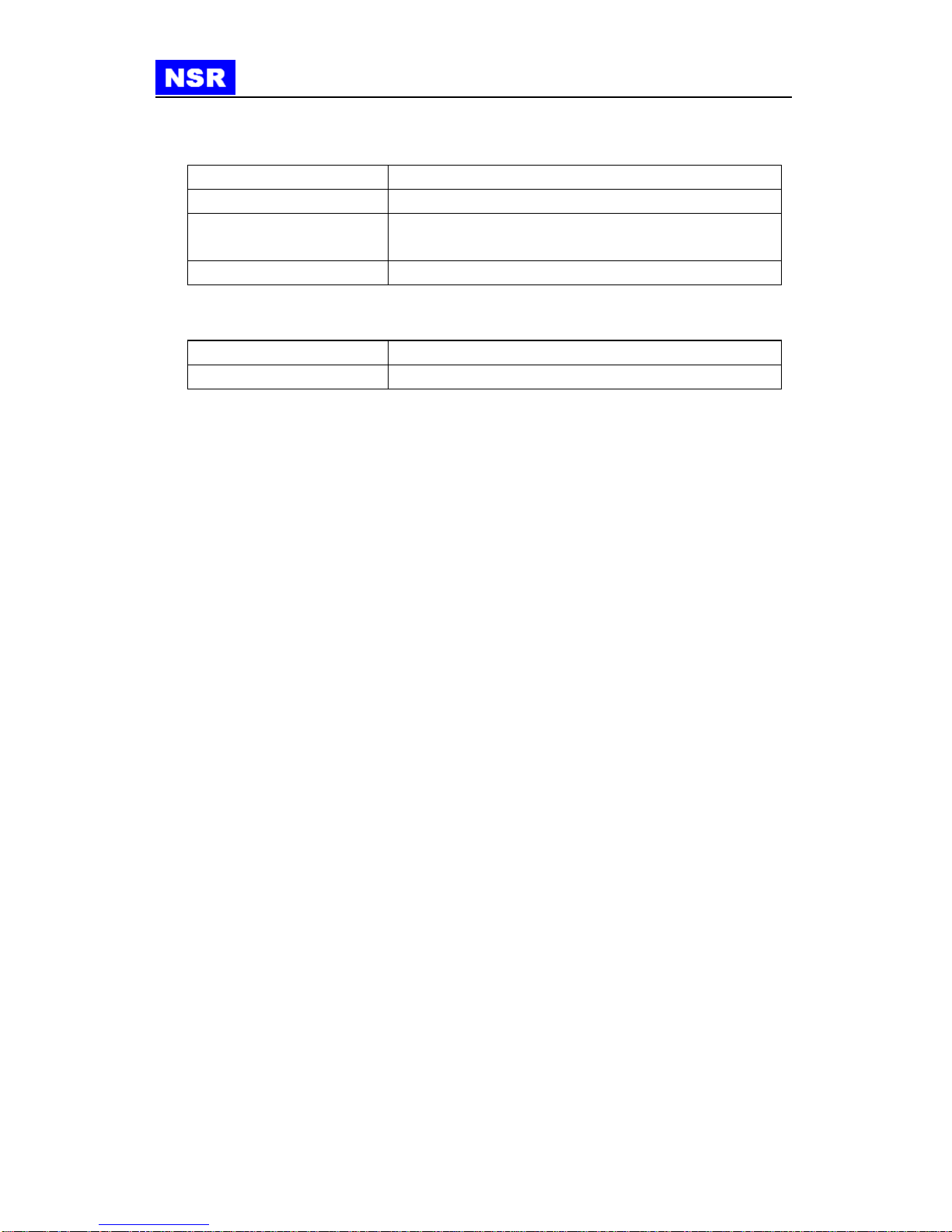
3.4 DSC FUNCTION
Signal format and protocol
Comply with the ITU-R M.493-11and M.541-9
Emission type
G2B
Modulation frequency
MARK(signal Y ) : 1,300Hz ±10Hz
SPACE(signal B ) : 2,100Hz ±10Hz
Transmission speed
1,200bps ±30 x 10-6
3.5 DEDICATED DSC RECEIVER (WKR)
Receive frequency
156.525MHZ (channel 70)
Sensitivity
Error rate≤1% when receiving signal=1μV

NVR-1000 MANUAL
NVR-1000 OM.E 20130216-002
5
4. STARTING SYSTEM
4.1 POWER ON
To start NVR-1000, follow the below steps:
①Power on the equipment by turning power switch (volume switch) clockwise.
②If the equipment is switched on initially,
program will be booted and it requires for MMSI
input as in right figure, then press ESC to return
to the initial screen and enter MMSI.
③If own ship’s MMSI is set, the initial screen will
be as the right figure when the equipment is
powered on.
④If program booting is completed, the initial screen will be displayed as right figure.
4.2 POWER OFF
To power off the equipment, turn the volume switch anti-clockwise until a “click”is
heard.
OWN SHIP’S MMSI
MMSI : 123456789
GROUP 1: 012345678
GROUP 2: 012345678

NVR-1000 MANUAL
NVR-1000 OM.E 20130216-002
6
5. BASIC OPERATION
5.1 KEYS ON THE FRONT PANEL
A distress key, menu keys, number keys, up/down keys are on the front panel.
MIC CONNECTION Power O
5.2 KEY DESCRIPTIONS
VOLUMNE
& POWER ON/OFF
To power on/off or to adjust speaker
volume.
SQUELCH
It is used to remove noise. Adjust the
squelch level slightly higher than point that
noise is removed.
Note: if squelch level is too high, weak
signal could be ignored.
DIMMER
Press F Key and then press ▲or ▼to
change the LCD backlight.
TX POWER
Set the transmitting power 25W or 1W.
CH UP/DOWN KEY
VOLUME & POWER ON/OFF
NOISE REDUCTION
FUNCTION KEY
CH70 KEY
CH16 KEY
SPEAKER
LCD
NUMERIC KEYS
DISTRESS KEY

NVR-1000 MANUAL
NVR-1000 OM.E 20130216-002
7
CHANNEL MODE
Change to desired channel mode among
ITU, USA, CAN channel.
WX CHANNEL
Change to weather channel mode (there are
10 channels in the weather mode).
PRIVATE
CHANNEL
Change to private channel mode.
5.3 BASIC OPERATION
When powered on, the equipment will be initialized and set the default channel as CH16.
①Initiate a voice call: Set the transceiver to a channel desired. Hang off the
microphone and press PTT button on the microphone and speak. “TX”will be
indicated on LCD while PTT is pressed. Release PTT button to change the transceiver
to the receiving status.
Note: During transmission, the speaker is automatically muted.
②End of call: After the voice call is completed, hang up the microphone and the
transceiver will return to CH16 in receiving mode automatically.
③DUALWATCHING: An additional channel and channel 16 is scanned. The additional
channel is sampled for 1.85s and channel 16 is sampled for 0.15s. To stop scanning,
press “ESC” button.
④Up/down key: It is to change the channel number or move a cursor in the menu
screen.
DUALWATCH:
In DUAL WATCH, Channel 16 and an additional channel will be scanned to be
watched. The additional channel can be selected by “F”key and “5/DW”key.
Generally, CH16 will be sampled for 0.15s while the additional channel is
sampled for 1.85s.
When a signal is detected on CH16 during sampling, the scanning will stop and
the receiver will stay on CH16 for receiving. As soon as the signal disappears on
CH16, the scanning between two channels will restore.
If a signal is detected on the additional channel during sampling, the transceiver
will continue the sampling of 0.15s on CH16 every 2s when receiving on the
additional channel. Whenever a signal is detected on CH16 during sampling, the
transceiver will stay on CH16 for receiving, by ignoring the signal on the
additional channel.
NVR-1000 MANUAL
NVR-1000 OM.E 20130216-002
8
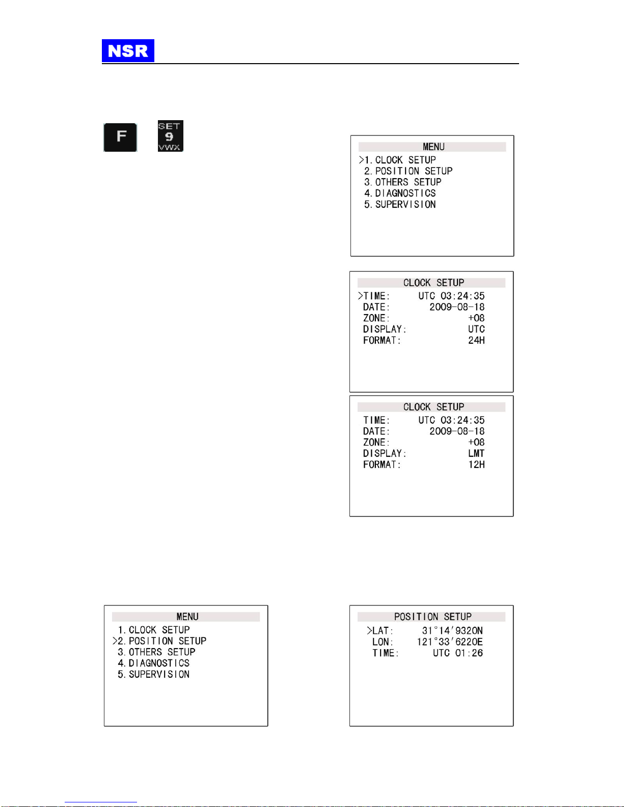
6. INITIAL SETUP
=>
Press two keys in turn to enter the MENU scree
n as in right figure. Press up/down or number
key directly to select the desired menu item.
To return to previous screen, press “ESC”key in
the menu screen.
6.1 CLOCK SETUP
①TIME SETUP: Press up/down to select the
setting item. Press “ENT” key on the cursor
position then the cursor would be highlighted
to configure current time. Press “ENT” again
after setting. If value is input incorrectly, use
up/down key to move position of highlighted
cursor and re-enter value.
②DATE SETUP: After the time set, move
cursor by using down key and enter
year/month/date in the same way with time
setup. ZONE and DISPLAY, FORMAT could
be changed in the same way.
If setup is completed, press “ESC” key and
confirm whether the input is correct, then press
“APPLY” to store the new setting.
6.2 POSITION SETUP
If a GPS receiver is connected, current position will be updated automatically. But if the
GPS receiver is not connected or the GPS data is not available, position data should be
entered manually. Input current position manually in the same way with time setting.
>
NVR-1000 MANUAL
NVR-1000 OM.E 20130216-002
9
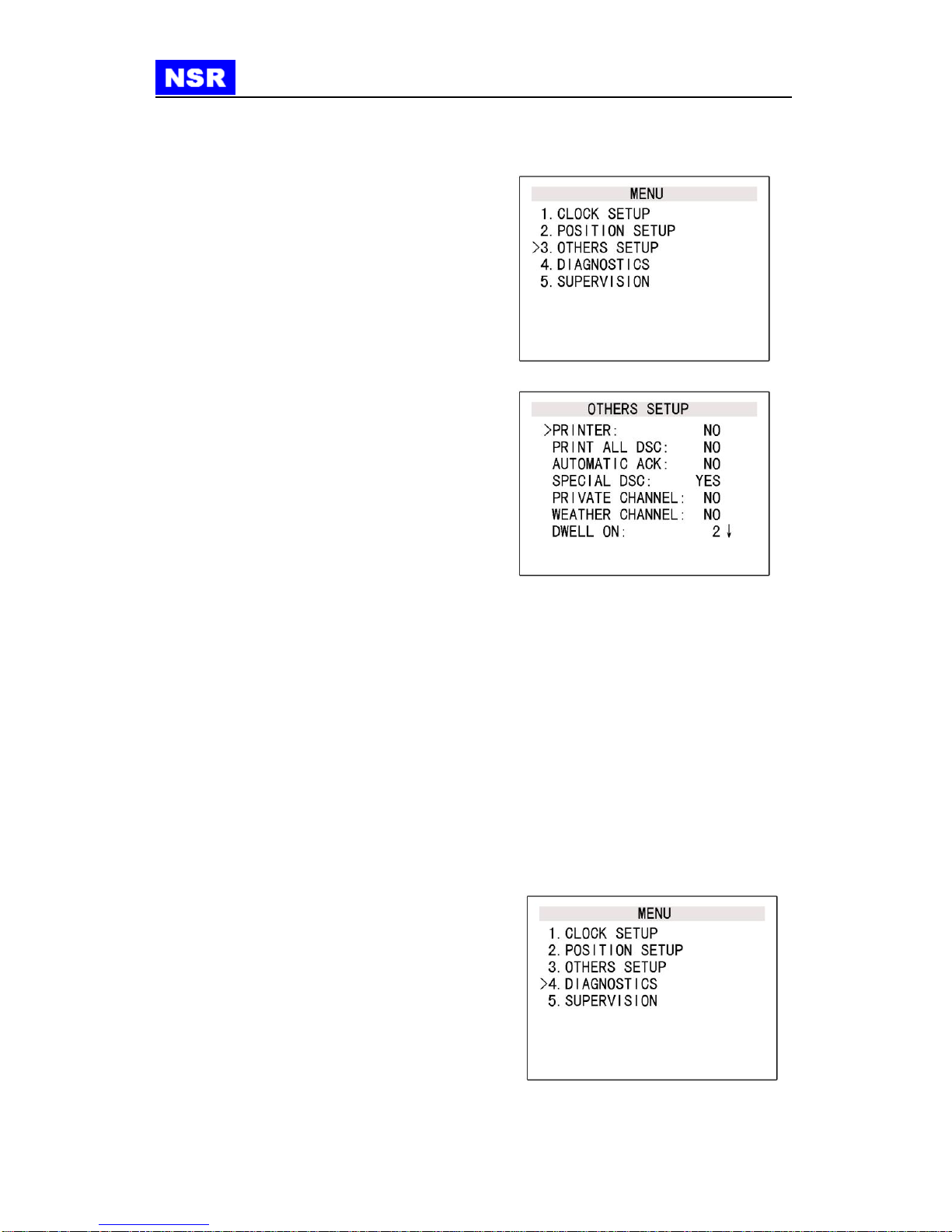
6.3 OTHERS SETUP
-PRINTER
Set YES to print DSC message whenever
received.
-PRINTALLDSC
Set YES to print all received DSC message.
If NO is set, only DISTRESS message will
be printed.
-AUTOMATICACK
If YES is set, the equipment will respond to
test message or position request message
automatically.
-SPECIAL DSC
If YES is set, detailed items are to be
selected:
1. ALL MODE TP.
2. MEDICAL X-PORTS.
3. SHIP&AIRCRAFT of TO ALL SHIPS of
URGENCY CALL in DSC menu.
-PRIVATE CHANNEL
If YES is set, private channel will be available.
-WEATHER CHANNEL
If YES is set, weather channel will be available.
-DWELL ON
It can be used to adjust the sampling time during scanning.
-BRIGHTNESS
Backlight is adjusted by four steps from 0 ~ 3.
(Brightness is adjustable by using “F” key and up/down key in the initial screen.)
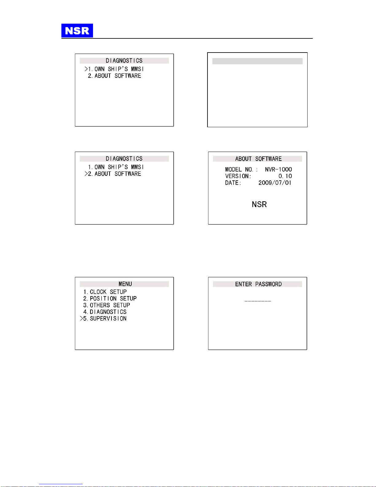
6.4 DIAGNOSTICS
It is to check own ship’s MMSI or current
software version.
It is to check own ship’s MMSI and group
ID and modification is not allowed here.
NVR-1000 MANUAL
NVR-1000 OM.E 20130216-002
10
Current software version can be checked.
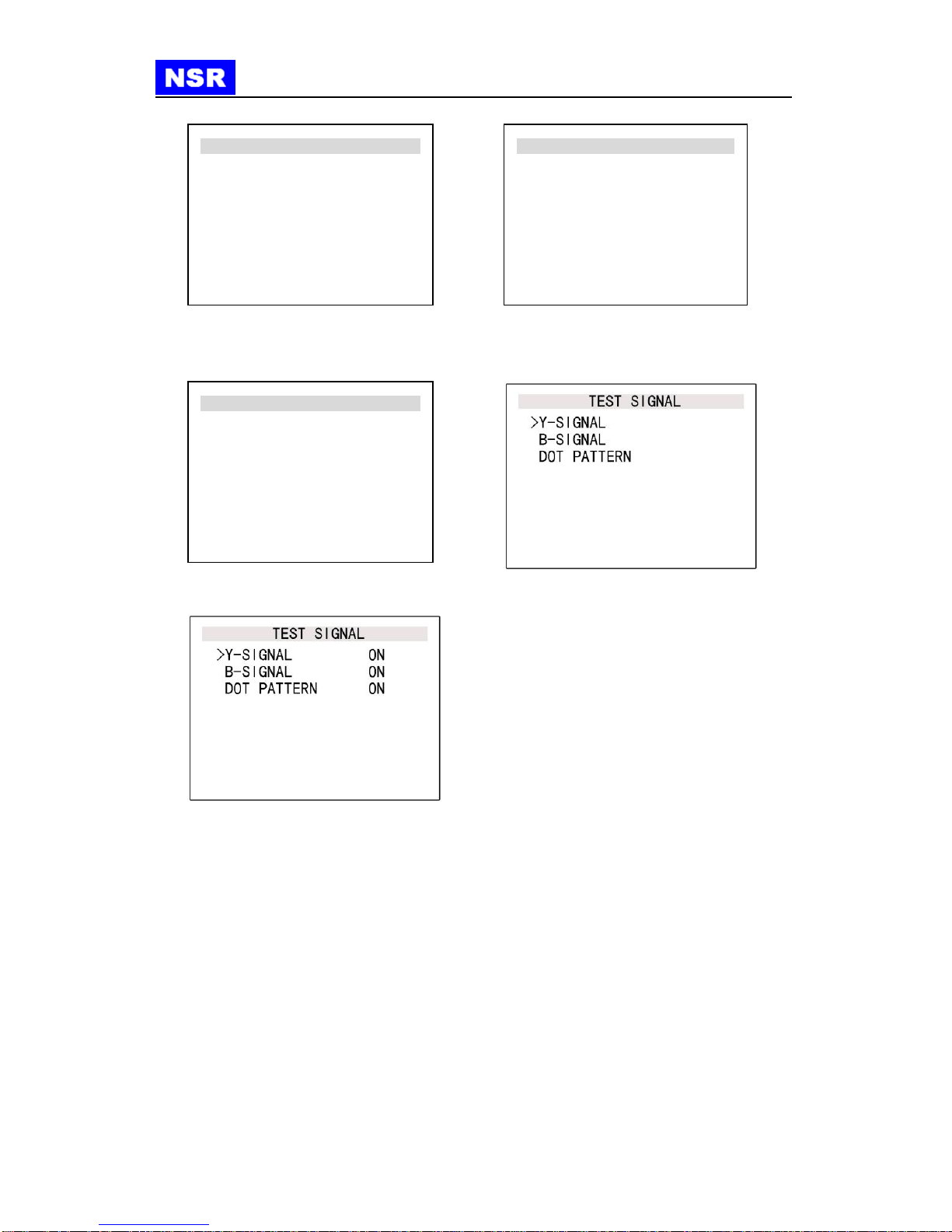
6.5 SUPERVISION
The access for SUPERVISION is only for authorized service engineers. The password is
required for the access. Please consult with the manufacturer for password information.
-MMSI setup
Own ship’s MMSI is individual MMSI assigned to the vessel by the authority.
GROUP 1 & GROUP 2 MMSIs are special for group DSC calling. Usually local
administration can define such group MMSI for certain vessels for safety concern.
Both group MMSIs can leave empty if unavailable.
OWN SHIP’S MMSI
MMSI : 123456789
GROUP 1: 012345678
GROUP 2: 012345678
NVR-1000 MANUAL
NVR-1000 OM.E 20130216-002
11
-TEST SIGNAL
Such test signal is used to diagnose the DSC facility within the equipment.
Select Enter.
SUPERVISION
> 1. MMSI SETUP
2. TEST SIGNAL
3. FACTORY DEFAULT
OWN SHIP’S MMSI
MMSI : 123456789
GROUP 1: 012345678
GROUP 2: 012345678
SUPERVISION
1. MMSI SETUP
> 2. TEST SIGNAL
3. FACTORY DEFAULT

NVR-1000 MANUAL
NVR-1000 OM.E 20130216-002
12
7. DSC CALLS
DSC (Digital Selective Calling) is an important mean for emergency calls at sea. It’s a
part of GMDSS (Global Maritime Distress and Safety System) set by IMO (International
Marine Organization).
DSC should be primarily used for distress, urgent and safety call and response to such
calls, in addition, it can be used for general service between ship to ship and ship to shore
station and if automatic service is provided for by coastal stations for direct access to
shore-based public telephone network.
7.1 MAKE A DSC CALL
=>
Press “F” and “7” key simultaneously to DSC
menu.
All items are as follows in DSC menu.
▪DISTRESS CALL
▪URGENCY CALL
▪SAFETY CALL
▪ROUTINE CALL
▪SEMI / AUTO VHF
▪RECEIVED CALL
7.1.1 DISTRESS CALL
There are two ways to make a distress call:
○
1Open cover of DISTRESS button on the
front panel of the equipment and press
button for about 5s.
○
2Send the call by using the DSC menu.
Select DISTRESS CALL to enter the
sub-menu.
-ALERT
Enter ALERT item to make a distress call.
The position data is included in the message. When a GPS receiver is connected, the
position will be updated automatically, otherwise the manual input is required. Send the
call when completed. The distress call is sent to all vessels.

NVR-1000 MANUAL
NVR-1000 OM.E 20130216-002
13
- ACK
It is to acknowledge a distress call.
- RELAY-ALLSHIPS
It is to relay a distress call to all vessels.
- RELAY –A STATION
It’s to relay a distress call to a station. A
particular MMSI is entered before send the
call.
- RELAYACK
It’s to acknowledge a distress relay.
SEND DSC
FORMAT : DISTRESS
FROM: 123456789
NATURE:
UNDESIGNATED
POSITION:
LAT: 30º14’9370N
LON: 121º33’6390E↓

NVR-1000 MANUAL
NVR-1000 OM.E 20130216-002
14
7.1.2 URGENCY CALL
Select URGENCY CALL to make an urgent call.
In the URGENCY CALL menu, there are two options, TO ALL SHIPS and TO A
STATION.
Select TO ALL SHIPS.
In the TO ALL SHIPS menu, select ALL MODE TP.
In the TOALLSHIPS menu, select MEDICAL X-PORTS.
SEND DSC
FORMAT : INDIVIDUAL
TO : 987654321
CATEGORY : URGENCY
FROM : 123456789
1 : ALL MODES TP
2 : NO INFORMATION
RX CH NO : 0006
↓
Table of contents


