- 13 -
ENGLISH GB
GENERAL
Carefully read the contents of this leaflet since it provides important
instructions regarding safety of installation, use and maintenance.
Keep the leaflet for possible future consultation. All the operations re-
lating to installation/replacement (electrical connections) must be
carried out by specialised personnel in conformity with the regulations
in force.
SAFETY WARNINGS
It is recommended to use flat-bottom pans with a diameter equal to or
slightly larger than that of the heated area. Do not use pans with a rough
base to prevent scratching the heat surface of the cooktop (Fig.2).
This appliance is not suitable for use by children or persons requiring
supervision. Do not let children play with the appliance.
IMPORTANT
- Avoid spilling liquid, therefore to boil or heat liquids, reduce the
heat.
- Do not leave the heating elements on with empty pots and pans or
without receptacles.
- When you have finished cooking, switch off the relevant heating
element with the control indicated below.
ATTENTION:Steamcleanersmustnotbe used.
WARNING:If thesurfaceiscracked, switchoffthe applianceto
preventelectricshock.
INSTALLATION INSTRUCTIONS
These instructions address specialised installers and serve as a guide
for installation, adjustment and maintenance in conformity with the
laws and regulations in force.
If a built-in oven or any other appliance that generates heat must be
fitted directly under the glass-ceramic cooktop, THIS APPLIANCE
(oven) AND THE GLASS-CERAMIC COOKTOP MUST BE SUIT-
ABLY INSULATED in such a way that the heat generated by the oven,
measured on the bottom right of the cooktop, does not exceed 60°C.
Failure to respect this precaution may determine improper functioning
of the TOUCHCONTROL system.
POSITIONING(Fig.1)
The domestic appliance is designed to be built into a worktop as illus-
trated in the specific figure. Apply sealant around the entire perimeter
(cut-out dimensions Fig.1B).
Fix the domestic appliance on the worktop by means of the 4 brackets
provided, taking the thickness of the worktop into account (Fig.1A). If
the lower part of the appliance, after installation, is accessible via the
lower part of the cabinet then it is necessary to mount a separator panel
respecting the distances indicated (Fig.1C). If the appliance is in-
stalled with an oven underneath then the separator is not necessary.
ELECTRICALCONNECTIONS
Before making the electrical connections, check that:
- the ground cable is 2 cm longer than the other cables;
- the system ratings meet the ratings indicated on the identification
plate fixed on the lower part of the worktop;
- the system is fitted with efficient earthing compliant to the laws and
regulations in force.
Earthing is obligatory by law.
If the domestic appliance is not fitted with a cable and/or relevant plug,
use material suited to the absorption value indicated on the identifica-
tion plate and the operating temperature. At no point must the cable
reach a temperature 50°C higher than room temperature.
If wishing to make a direct connection to the mains, an omnipolar
switch must be interposed with a minimum opening of 3 mm between
the contacts and suited to the load indicated on the plate and conform
to the regulations in force (the yellow/green ground conductor must not
be interrupted by the switch). When the appliance has been installed,
the omnipolar switch must be easily reachable.
USE AND MAINTENANCE
MAINTENANCE
Remove any residues of food and drops of grease from the cooking
surface using the special scraper supplied on request (Fig.3)
Clean the heated area as thoroughly as possible using SIDOL,
STAHLFIX or similar products and a cloth/paper, then rinse with water
and dry with a clean cloth.
Using the special scraper (optional) immediately remove any frag-
ments of aluminium and plastic material that have unintentionally melted
on the heated cooking area or residues of sugar or food with a high
sugar content (Fig.3).In this way, any damage to the cooktop surface
is prevented.
Under no circumstances use abrasive sponges or irritating chemical
detergents such as oven sprays or stain removers.
USE
Use the touch control system in the corresponding position relative to
the individual cooking needs. Keep in mind that the higher the number,
the more heat that it is produced.
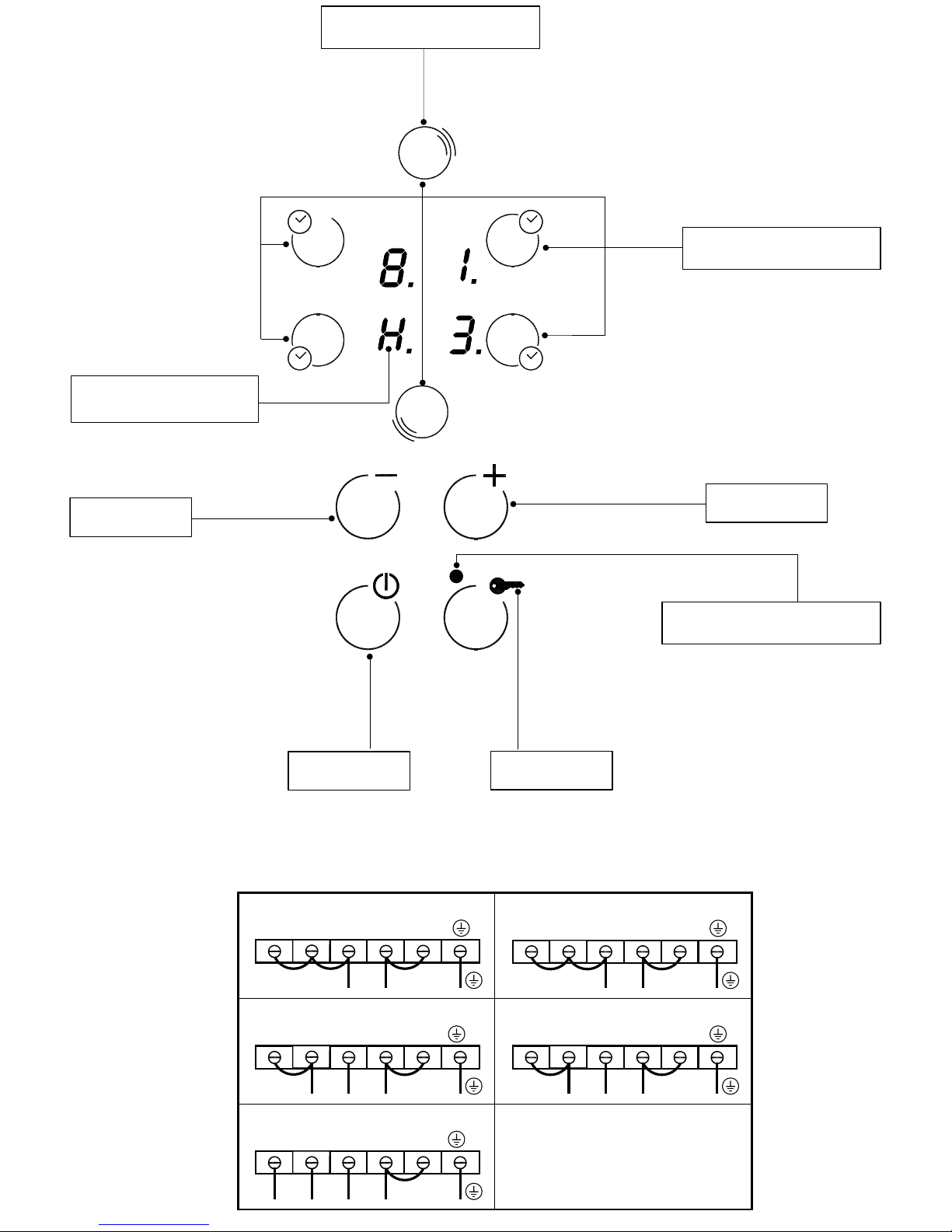
FUNCTIONING
- On the basis of the model you own, the appliance can be switched on
by actuating the start-up sensor (Fig.4-5-6-7-8 A). One zero will ap-
pear on all displays within10 seconds. If no display is actuated within
10 seconds, the top will switch off again.
- Press selection key Ffor the desired cooking area.
A luminous "0" will appear on the respective display with a decimal
point to indicate which cooking area is active.
- A hotplate may be switched on by activating the "+" or "-" sensor
within 10 seconds. If sensor Dis used, the display will show selection
9, while if sensor Cis used, the display shows selection 1 or 5, depend-
ing on the model.
- Once this operation has been performed choose the temperature
adjustment with the "+" or "-"keys.
- The plate can be switched off by selecting "0" with the D sensor, after
3 seconds the cooking area is automatically switched off.
It is always possible to switch a plate off by touching the "+"and "-"
sensors at the same time.
- The cooking top can be switched off by touching the main start-up
sensor (Fig.4-5-6-7-8 A). If all the plates are selected on "0" the top will
switch off after 10 seconds.
-If the top is equipped with plates with an extension (fig.5- 7-8) switching
on of the second area will be carried out after having checked that :
- the key button LED (fig.5-7-8 B) is off, otherwise de-insert it.
- Press the key (fig.5-7-8 A) to switch the top on.
- Choose the desired plate and adjust the power using the "+"or "-"
keys.
-Once the power has been adjusted choose the key (fig.5-7-8 L) to
activate the double area.
-To deactivate the double area check that the interested plate has been
selected (fig.5-7-8 F) and press the key (fig.5-7-8 L) .
Note:the Double area function is activated only on plates F1and F2
(fig.5-7-8 ).
- If an object is placed above the controls, the cooking top will
automatically move to the OFF position.
When a plate is in the OFFposition and the temperature is higher than
50° there will be a luminous signal "H" near to the respective selection
key (Fig.4- 5- 6-7-8 H).
- the Bfunction blocks the functioning of the top on selection. E.g.: if the
function is activated while the top has two areas switched on the
programme remains blocked even if you try to switch another area on.
The same thing happens if the appliance is switched off and the function
is activated; the top doesn't switch on.
To activate or deactivate it hold a finger on the B sensor for about two
seconds. The function is active when warning light Eis switched on.
Timer(Fig.5).
- Select the plate with the relative power.
- Press the selection key again of the already-activated plate.
- Using the "+" and "-"keys set the desired time.
- The decimal point at the side of the power level will indicate that the
plate has the TIMERfunction activated.
- An acoustic signal will indicate switching off of the cooking area.
THEMANUFACTURERDECLINESALLRESPONSIBILITY
FOR EVENTUAL DAMAGES CAUSED BY BREACHING
THEABOVEWARNINGS.


LPG operating instructions")


