Newport Oriel 60000 Q User manual
M60000
Please read these instructions completely before operating this equipment. The specification and operating
instructions apply only to the model(s) covered by this manual. If there are any questions or problems regarding the
use of this equipment, please contact Newport or the representative from whomthis equipment was purchased.
Rev: 07.31.13
150 Long Beach Boulevard
Stratford, CT 06615
Phone: (203) 377-8282
(800) 714-5393
Fax: (203) 378-2457
E-MAIL: oriel.sales@newport.com
SERIESQ HOUSING
MODELS60000,60030
USER MANUAL

M60000
SERIES Q CONVECTIVE LAMP HOUSING
2
TABLEOF CONTENTS
1. INTRODUCTION ........................................................................................................................................................4
2. SAFETY CONSIDERATIONS....................................................................................................................................9
2.1 RADIATION ..............................................................................................................................................9
2.2 LAMP EXPLOSION - XENON AND MERCURY ARC LAMPS .............................................................9
2.3 OZONE ...................................................................................................................................................10
2.4 ELECTRICAL..........................................................................................................................................10
2.5 EMI..........................................................................................................................................................11
2.6 HEAT.......................................................................................................................................................11
3. GENERAL DESCRIPTION ......................................................................................................................................12
3.1 LAMP AND REFLECTOR ADJUSTMENTS .........................................................................................12
3.2 LAMP COOLING....................................................................................................................................12
3.3 OPTIONAL CONDENSING LENS ASSEMBLIES................................................................................12
3.4 MOUNTING ............................................................................................................................................12
4. CONFIGURATION OPTIONS AND A CCESSORIES .............................................................................................15
4.1 INTERFACE KITS..................................................................................................................................15
5. ARC LA MP KIT MODEL 60010, 66017...................................................................................................................17
5.1 INSTALLATION OF ARCLAMP INTERFACE KIT ..............................................................................17
5.2 INSTALLATION OF SOCKETADAPTERS ANDARCLAMPS ..........................................................17
5.3 ELECTRICAL CONNECTIONS.............................................................................................................17
5.4 INSTALLATION OF VENTS ..................................................................................................................20
5.5REASSEMBLE Q-HOUSING SHELL....................................................................................................20
6. ARC LA MP KIT MODEL 60025 ...............................................................................................................................21
6.1 INSTALLATION OF ARCLAMP INTERFACE KIT, MODEL 60025 ...................................................21
6.2 INSTALLATION OFSOCKETADAPTERS ANDARCLAMPS ..........................................................21
6.3 ELECTRICAL CONNECTIONS.............................................................................................................21
6.4INSTALLATION OF INTERLOCK ACTUATOR....................................................................................23
6.5 INSTALLATION OF VENTS ..................................................................................................................23
6.6 REASSEMBLE Q-HOUSING SHELL....................................................................................................23
7. QTH A ND IR ELEMENT INTERFA CE KIT MODEL 60020 ....................................................................................25
7.1 INSTALLATION OF THE LAMP INTERFACE KIT...............................................................................25
7.2 INSTALLATION OF SOCKETADAPTER LAMPS & IR ELEMENTS .................................................25
7.3 REASSEMBLE THE Q-HOUSING SHELL...........................................................................................25
8. DEUTERIUM INTERFA CE KIT MODEL 60093 ......................................................................................................27
8.1 INSTALLATION OF THE LAMP INTERFACE KIT...............................................................................27
8.2 INSTALLATION OF SOCKETADAPTER AND LAMP ........................................................................27
8.3 REASSEMBLE THE Q-HOUSING SHELL...........................................................................................28
9. DEUTERIUM INTERFA CE KIT MODEL 60023 ......................................................................................................30
9.1 INSTALLATION OF THE LAMP MOUNT AND DEUTERIUM INTERFACE PANEL .........................30
9.2 DEUTERIUM LAMP INSTALLATION ...................................................................................................30
9.3 ELECTRICAL CONNECTIONS.............................................................................................................30
9.4REASSEMBLE THE Q HOUSING SHELL ...........................................................................................30
10. PULSED DEUTERIUM INTERFA CE KIT MODEL 60024 ......................................................................................32
10.1 INSTALLATION OF INTERFACE KIT...................................................................................................32
10.2 REASSEMBLE THE Q-HOUSING........................................................................................................32
11. CA PILLARY A ND GUIDED LA MP INTERFA CE KIT MODEL 66015, 66016 .......................................................34
12. QTH A ND IR INTERFA CE KIT MODEL 60090 .......................................................................................................36
12.1 INSTALLATION OF THE LAMP INTERFACE KIT...............................................................................36
12.2 INSTALLATION OF SOCKETADAPTER, LAMP & IR ELEMENTS...................................................36
12.3 REASSEMBLE THE Q-HOUSING SHELL...........................................................................................36
13. ADJUSTMENT OF LAMP, MIRROR AND LENS WITH THE 60005 REFLECTOR ASSEMBLY .........................38
13.1 GENERAL...............................................................................................................................................38
13.2 ADJUSTMENTS PRIOR TO OPERATION...........................................................................................38
13.3 ADJUSTMENT DURING OPERATION ................................................................................................38
13.4 LAMP OPERATIONAND COOLING....................................................................................................39

M60000
SERIES Q CONVECTIVE LAMP HOUSING
3
14. LIGHT COLLECTION ...............................................................................................................................................40
14.1 COLLIMATED BEAMS...........................................................................................................................41
14.2 IMAGING THE SOURCE.......................................................................................................................42
14.3 UNIFORMITY .........................................................................................................................................43
14.4 REAL LENSES.......................................................................................................................................44
SPHERICAL ABERRATION ...............................................................................................................44
CHROMATIC ABERRATION..............................................................................................................45
14.5 HOW DO YOU POSITION THE CONDENSER TO GET A COLLIMATED BEAM? ..........................45
15. ADDITIONAL OPTIONS FOR THE Q-HOUSING ..................................................................................................46
15.1 ADAPTER KIT FOR INTENSITY CONTROLLER SYSTEM ...............................................................46
15.2 HEAT ISOLATORADAPTER KIT.........................................................................................................47
15.3 ELECTRONIC SAFETY SHUTTER ......................................................................................................47
16. TROUBLESHOOTING .............................................................................................................................................49
16.1 INTRODUCTION....................................................................................................................................49
16.2 PROBLEMS............................................................................................................................................49
17. DECLA RATION OF CONFORMITY ........................................................................................................................51
18. WARRA NTY A ND RETURNS .................................................................................................................................52
LIST OF FIGURES
Figure 1 : Various Light Collection Options for the Series Q Housing.................................................. 7
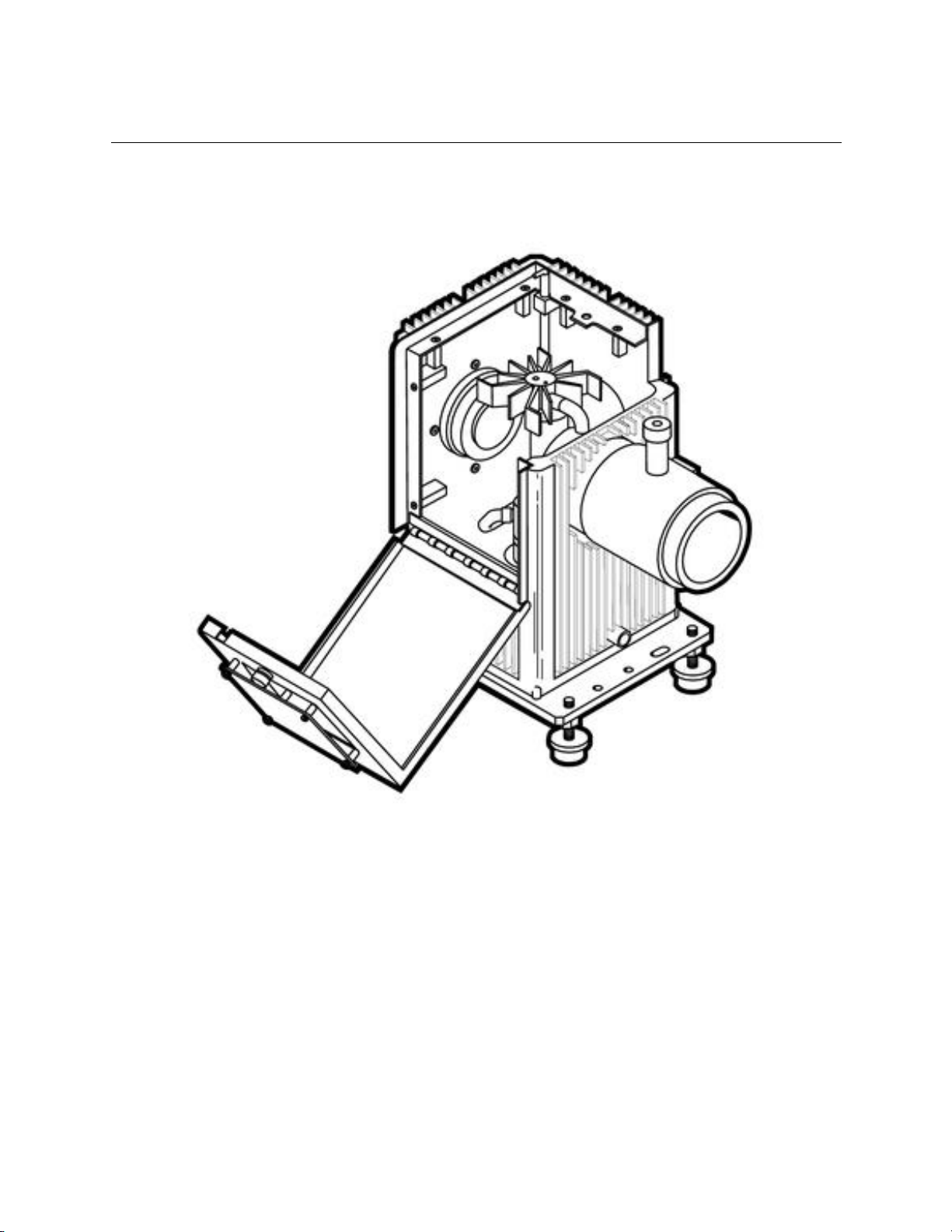
Figure 2 : 60030 Hinged Q Housing.............................................................................................. 8
Figure 3 : Series Q Housing and Components...............................................................................13
Figure 4 : Dimensional...............................................................................................................14
Figure 5 : Mounting Arc Lamp Interface toSeries Q Housing...........................................................16
Figure 6 : Interface Kit 60010......................................................................................................18
Figure 7 : Arc Lamp Orientation...................................................................................................19
Figure 8 : Series Q-Housing withVents........................................................................................20
Figure 9 : Series Q-Housing 60025 Interface Kit ............................................................................22
Figure 10 : Series Q-Housing withVents and Interlock....................................................................24
Figure 11 : QTH Glower Mounting Configuration............................................................................26
Figure 12 : 60093 Interface Kit....................................................................................................29
Figure 13 : Deuterium Lamp Mounting Configuration......................................................................31
Figure 14 : Pulsed Deuterium Lamp Mounting...............................................................................33
Figure 15 : Model 6426 0.32 Joule Guided Arc Lamp......................................................................34
Figure 16 : Pulsed Arc Lamp Mounting.........................................................................................35
Figure 17 : 60090 Interface Kit Assembly......................................................................................37
Figure 18 : The electrodes as viewed on ascreen in front ofthe condenser lens are inverted (right)......39
Figure 19 : Correctly positioned reflector overlays the inverted arc image on the arc gap......................39
Figure 20 : Collimated Beam.......................................................................................................41
Figure 21 : A source focused to a smaller image............................................................................42
Figure 22 : The collimate output of a 200W Hg lamp in the vertical and horizontal planes.....................43
Figure 23 : Spherical Aberration..................................................................................................44
Figure 24: Chromatic aberration: different wavelengths are focused at different points........................45
Figure 25 : Typical Intensity Controller System..............................................................................46
Figure 26 : 68954 Adapter Kit Mounting to the Q Series Housing......................................................47

M60000
SERIES Q CONVECTIVE LAMP HOUSING
4
1. INTRODUCTION
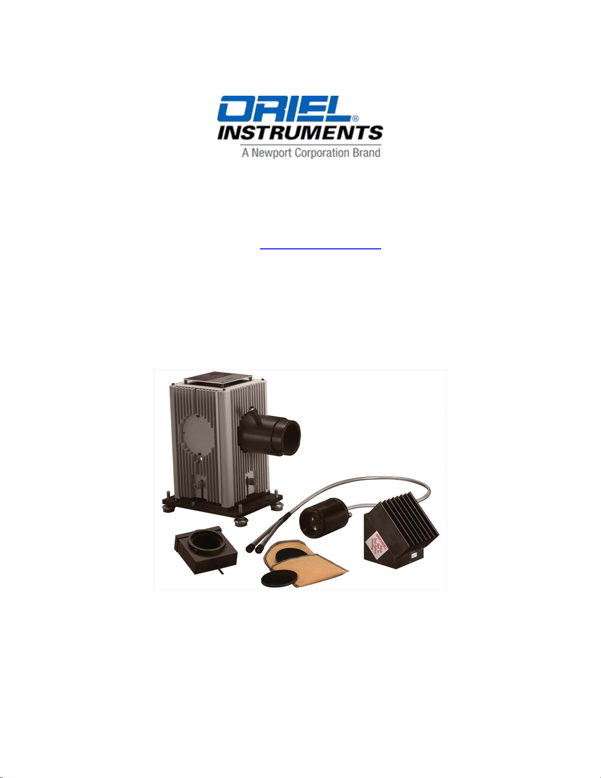
The 60000 Series Q is a modular, convectively cooled lamp housing with four output ports. The lamp base has
external knobs to allow lamp position adjustment during operation in X, Y, Zdirections.
Since the product is fanless, free of airborne noise, and accommodates light sources up to 100 W, the ex terior
has been designed with cooling fins to reduce heat through natural convection.
The 60000 can accommodate 16 light sources with several mounting arrangements. The housing can be
converted, by the user, to operate arc, tungsten halogen, and deuterium lamps as well as IR sources. Table 1
shows the appropriate interface kit and socket adapter for each lamp. Complete Series Q Housings with a
choice of lamp (and mount) are available. See Newport catalog for specific configurations.
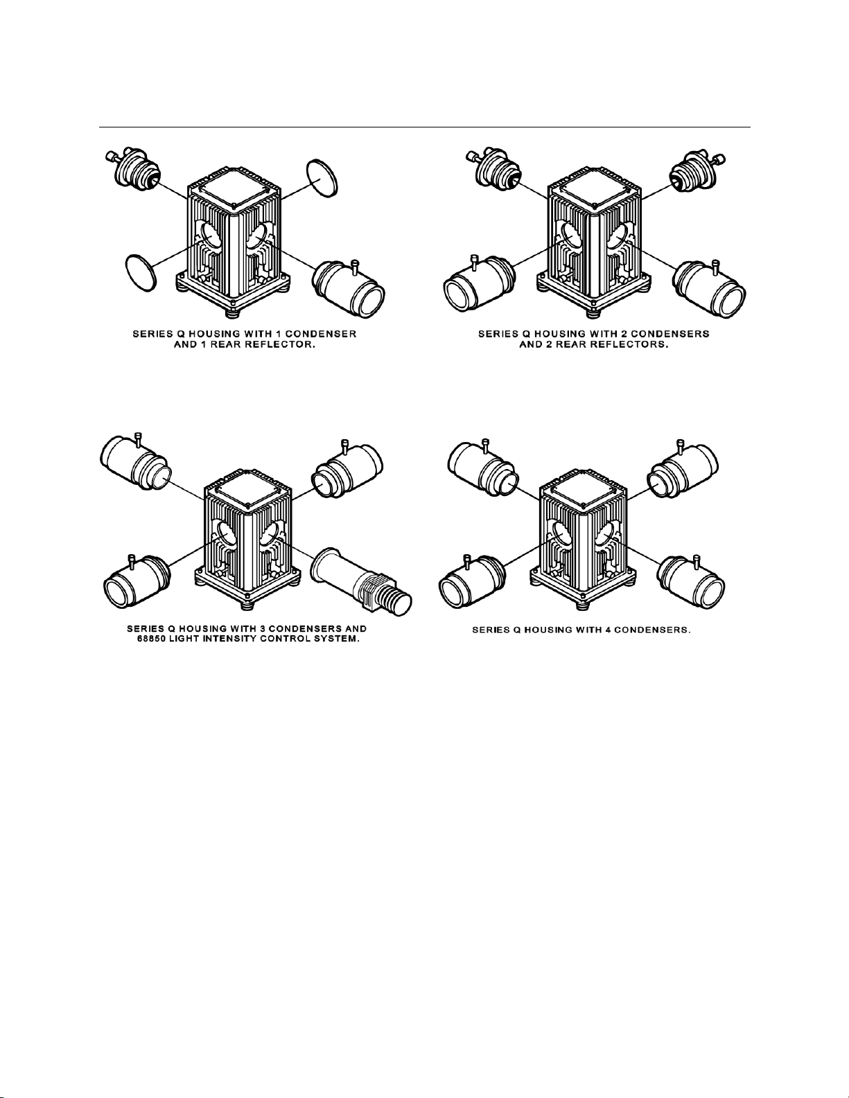
A number of accessories can be used in conjunction with the Series Q. One or more adjustable reflectors can
be mounted on the output ports to maximize light output. Similarly, lens assemblies are available t o c ollimate
the radiation or re-image the source. Figure 1 shows the various configurations.
The model 60030 is a specialized arc lamp version Q housing that incorporates a hinged cover. Swing the
cover open and you’ll be able to install or replace your lamp without having to remove the outer shell and disturb
any connected equipment. Built into the 60030 is our CE marked arc lamp ignitor and interface kit. Three
output ports allow integration of the same accessories as the standard 60000 although the port count is reduced
from 4 to 3. The 60030 uses the same arc lamps and adapters as the standard 60000.
Please check the Manuals section of our web site for any updates to this document.
M60000
SERIES Q CONVECTIVE LAMP HOUSING
5
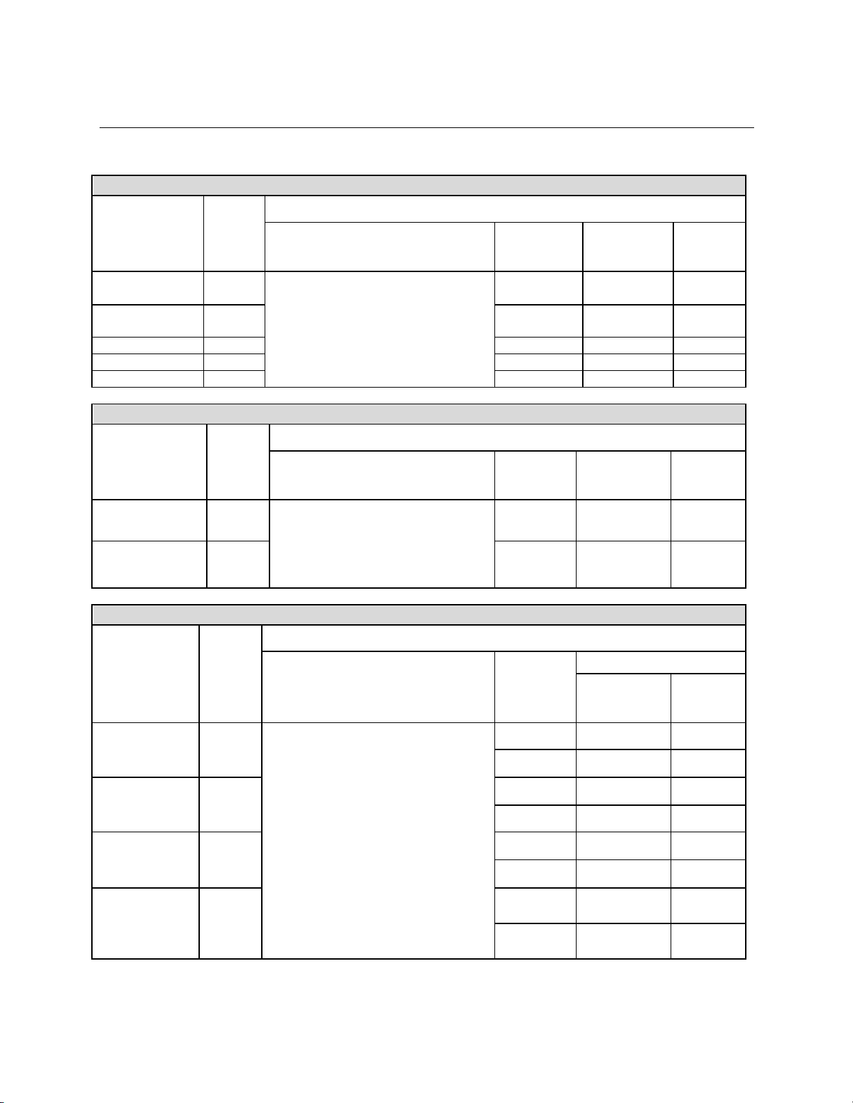
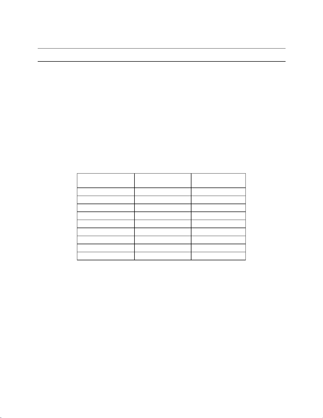
Table 1: APPROPRIATEINTERFACEKIT AND SOCKET ADAPTERS
DC Arc Lamps
Source Type
Lamp
Required Components
SeriesQ Housing
Interface
Kit
Socket
Adapter
Power
Supply
75 W Xe
6251N
S
60000 Series Q Housing with 4
ports (up to 4 condensers, 2 rear
reflector assemblies)
60030 Q Housing with 3 ports
(up to 3 condensers, 1 rear
reflector assembly)
60025
60014
69907
75 W Xe
Ozone Free
6263
60025
60014
69907
50 W Hg
6282
60025
60013
69907
100 W Hg
6281
60025
60012
69907
100 W Xe
6257
60025
60014
69907
Pulsed Arc Lamps
Source Type
Lamp
Required Components
SeriesQ Housing
Interface
Kit
Socket
Adapter
Power
Supply
0.32 J
Guided Xe
6426
60000 Series Q Housing with 4
ports (up to 4 condensers, 2 rear
reflector assemblies)
66016 *
60018
68825 *
0.5 J
Large Bulb Xe
6427
66017 *
60019
68826 *
DeuteriumLamps
Source Type
Lamp
Required Components
SeriesQ Housing
Interface
Kit **
Power Supply
Basic
Model
Full
Featured
Model
30W High
Uniformity
Ozone Free
63161
60000 Series Q Housing
with 1 condenser
60023 *
68840 *
60093
68942
30 W High
Uniformity,
Full Spectrum
63162
60023 *
68840 *
60093
68942
30 W High
Irradiance,
Full Spectrum
63163
60023 *
68840 *
60093
68942
30 W High
Irradiance and
Stability,
Ozone Free
63165
60023 *
68840 *
60093
68942
* Not CE marked.
** DC Deuterium lamp interface kits include the socketadapter.
M60000
SERIES Q CONVECTIVE LAMP HOUSING
6
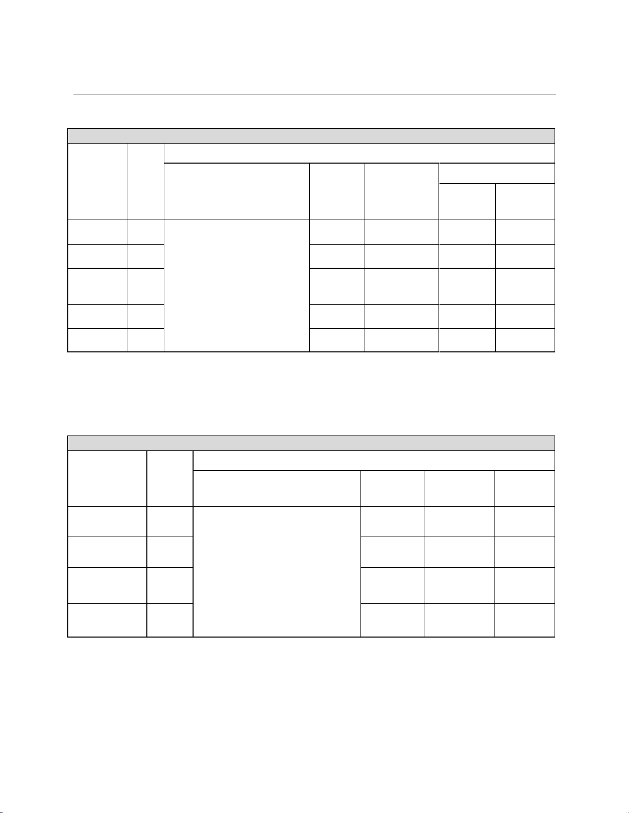
Quartz Tungsten Halogen (QTH) Lamps
Source
Type
Lam
p
Required Components
SeriesQ Housing
Interface
Kit
Socket
Adapter
Power Supply
Basic
Model
Full
Featured
Model
10 W
6318
60000 Series Q Housing with
4 ports (up to 4 condensers,
2 rear reflector assemblies)
60090
60042 (H)
60045 (V)
68938
20 W
6319
60090
60042 (H)
60045 (V)
68938
50 W
short
filament
6332
60090
60043 (H)
60046 (V)
68938
69931
50 W long
filament
6337
60090
60043 (H)
60046 (V)
68938
69931
100 W
6333
60090
60043 (H)
60046 (V)
68938
69931
(H) indicates lamp is mounted horizontally.
This mounting configuration is best suited for imaging the filament onto vertical monochromator slits.
(V) indicates lamp is mounted vertically.
Infrared Sources
Source Type
Source
Model
Required Components
SeriesQ Housing
Interface
Kit
Socket
Adapter
Power
Supply
IR Emitter
6363
60000 Series Q Housing with 4
ports
(up to 4 condensers, 2 rear
reflector assemblies)
60090
60041
68938
Ceramic
Element
6575
60090
60048
68938
Low Cost
Ceramic
Element
6580
60090
60048
68938
Miniature IR
Element
6581
60090
60048
68938
M60000
SERIES Q CONVECTIVE LAMP HOUSING
7
Figure 1 : VariousLight CollectionOptionsfor the SeriesQ Housing
M60000
SERIES Q CONVECTIVE LAMP HOUSING
8
Figure 2 : 60030 HingedQ Housing

M60000
SERIES Q CONVECTIVE LAMP HOUSING
9
2. SAFETY CONSIDERATIONS
There are six hazards in the operation ofthe 60000 SeriesQ Lamp Housing.They are:
Radiation
Lamp explosion
Ozone
Electrical shock
EMI
Heat
2.1 RADIATION
The high intensity UV and VIS radiation of the arc (including deuterium) lamps can permanent ly
damage the cornea, lens, and retina of the eye, even causing blindness. This damage may not be
immediately apparent. The deep UV is absorbed in the cornea or eye fluids; focused VIS and
NUV can damage the retina. Normal blink reaction to visible light may not be adequate protection,
and a beam of invisible NUV (produced by spectral filtering) can be most dangerous, as the blink
response is not induced. UV radiation can also cause painful sunburn, and with prolonged
exposure, serious burns.
Recommendations:
•Never look directly into the output beam from an arc lamp housing.
•Do not look at the specular (mirror) reflection of the beam.
•Always wear UV protective eyewear or facemask, and gloves. (If your arms will be in and out
of the beam wear long sleeves.)
2.2 LAMP EXPLOSION - XENON AND MERCURY ARC LAMPS
When xenon arc lamps are cold, they are under several atmospheres of pressure and may
explode due to internal strains or physical abuse. When hot, xenon and mercury arc lamps have
internal pressures of approximately 100 atmospheres and the possibility of violent explosion
exists.
Fingerprints and other contaminants left on the lamp cause a deterioration ofthe envelope during
operation and may lead to lamp explosion.
Recommendations:
•Do not handle a bare arc lamp without safety goggles and protection for exposed areas of
skin. Wear cleanroom quality gloves when handling lamps.
•Do not apply torque to the lamp envelope during installation or removal.
•Do not touch the lamp envelope with your fingers.
•Thoroughly clean the envelope before installation in the housing with alcohol or a dilute
solution of detergent and water.

M60000
SERIES Q CONVECTIVE LAMP HOUSING
10
In normal operation lamp explosions are rare and only occur after many hundreds of hours of
use. However, if the lamp envelope is stressed, explosion is more likely. Stress can occ ur from
improper mounting for from deterioration of the lamp envelope.
2.3 OZONE
Ultraviolet light can photo decompose molecular oxygen with subsequent formation of O3 - Ozone
is a common pollutant at ground level in urban areas. Relatively low concentrations of ozone can
cause nasal dryness and a burning sensation in the throat, headaches, nausea, and irritation of
the mucous membranes.
A 150 W UV arc lamp can contribute more than 1 part ozone per million to the convective air
stream. This may be of little consequence in a well-ventilated area but some people are very
sensitive to ozone and the long-term effects are not well documented. Noticeable symptoms for
most people appear at 0.3 - 0.5 ppm.
Recommended maximum exposures are typically:
0.1 ppm for 8 hours exposure
2 ppm ora 2-hourexposure
Recommendation:
•Use an ozone free lamp unless you need the shortwave UV.
Note: Ozone has an absorption in the UV. If ozone is created and built up in the opt ical path,
particularly a long enclosed optical path, then the observed UV radiation level may change
accordingly and lead to misinterpretation of lamp or sample performance.
2.4 ELECTRICAL
A high transitory voltage is used to ignite arc lamps. The lamp terminals have a potential
difference of up to 200 V prior to lamp start.
<< W ARNI NG >>
•Keep personnel clear of all exposed terminals.
•Before changing lamps or working on the system, disconnect input power and check the
power supply voltmeter for zero voltage to be sure that internal capacitors are fully
discharged.
•Make sure all connections are securely made (and check the polarity) before starting a lamp.
•Do not handle lamp leads during lamp ignition.
M60000
SERIES Q CONVECTIVE LAMP HOUSING
11
2.5 EMI
Ignition of a xenon arc lamp requires high voltage/high frequency pulses. Mercury arc lamps c an
also be started in this way or by using a voltage ramp as in our "Soft Start" ignitor. In both cases
a high current discharge follows. The ignition pulses particularly, but also the high starting
currents, are sources of radiated and conducted electromagnetic interference. Good earthing,
cable routing practice, and EMI shielding may be necessary to protect sensitive digital c ircuitry
from these pulses.
Recommendations:
•Start the arc lamp before powering nearby computer systems.
•Keep the computer away from the ignitor/power supply.
•Use a different outlet and line for the computer and ignitor/power supply.
•Contact Newport for special cabling (for which there will be an additional expense) to reduce
EMI/associated problems.
2.6 HEAT
Depending on the total wattage dissipated in the housing, the fins and convective cap on top will
get very hot. The lamp is also very hot after several minutes of operation, and remains hot for
some time after being shut off.
<< WARNING >>
•With the exception of the thermally insulated knobs on the base, adjustable reflector and lens
focus, never touch the lamp housing when in use.
•Allow the housing to cool before touching the exterior or before accessing the interior.
•Do not touch the lamp envelope and ends or adapters without allowing for enough cooling
down time.

M60000
SERIES Q CONVECTIVE LAMP HOUSING
12
3. GENERAL DESCRIPTION
The 60000 Series Q Lamp Housing is Newport's most modular lamp housing. Figure 3 shows the
components available for the 60000 to convert it from an arc to incandescent to deuterium to ceramic
element lamp housing. The four ports can support condensers or rear reflectors. Figure 1 shows the
various port configurations.
3.1 LAMP AND REFLECTOR ADJUSTMENTS
The location of the arc or filament changes from source to source due to normal manufac turing
tolerances. The 60000 has precision independent X, Y, and Z external lamp controls to
compensate for these variations. You can adjust the source 0.25 inches (6.4 mm) in any direction.
Moving the source moves any subsequent image, and allows you to precisely set an image on a
target.
The rear reflector assembly, model 60005, has control knobs that provide X, Y, and Z adjustments
for tilt and focus. The 60005 can be ordered from the Newport catalog.
3.2 LAMP COOLING
The Series Q uses natural convection (air) cooling. This is acoustically quiet and vibration free so
the lamp output is more stable than in fan cooled housings. Openings in the bottom and top of the
housing allow air to enter and circulate through the housing without excessive light leakage. The
ribbed exterior improves cooling of the lamp.
The Lamp housing is designed to operate in a typical laboratory environment (typically 68 to 76
degrees F, up to 45% relative humidity). Temperature and humidity outside of typical laboratory
range can contribute to cooling and ignition faults. Cooling issues will cause the over
temperature sensor to open and high humidity will cause ignition problems. Cont act Newport
technical representative for more information if operating outside the suggested range.
3.3 OPTIONAL CONDENSING LENS ASSEMBLIES
The 60000 does not come with a condenser. You can choose one of the following from the
Newport catalogue:
60006 Condensing/Collimating Lens Assembly F/1.5, UV grade fused silica
60007 Condensing/ImagingLens Assembly F/2.2, Series Q
60008 Condensing/Collimating Lens Assembly F/0.85, molded Pyrex aspheric
60009 IR Condensing/Collimating Lens Assembly F/1.1, Germanium
60076 Condensing/Collimating Lens Assembly F/1, UV grade fused silica
60077 IR Condensing/CollimatingLens Assembly F/1, Zinc Selenide
67008 Condensing/Aspheric Collimating Lens Assembly F/2.2, Q-Housing
67017 Condensing/Aspheric CollimatingLens Assembly F/1 Series Q
67018 Condensing/Focusing Lens Assembly F/1 Series Q
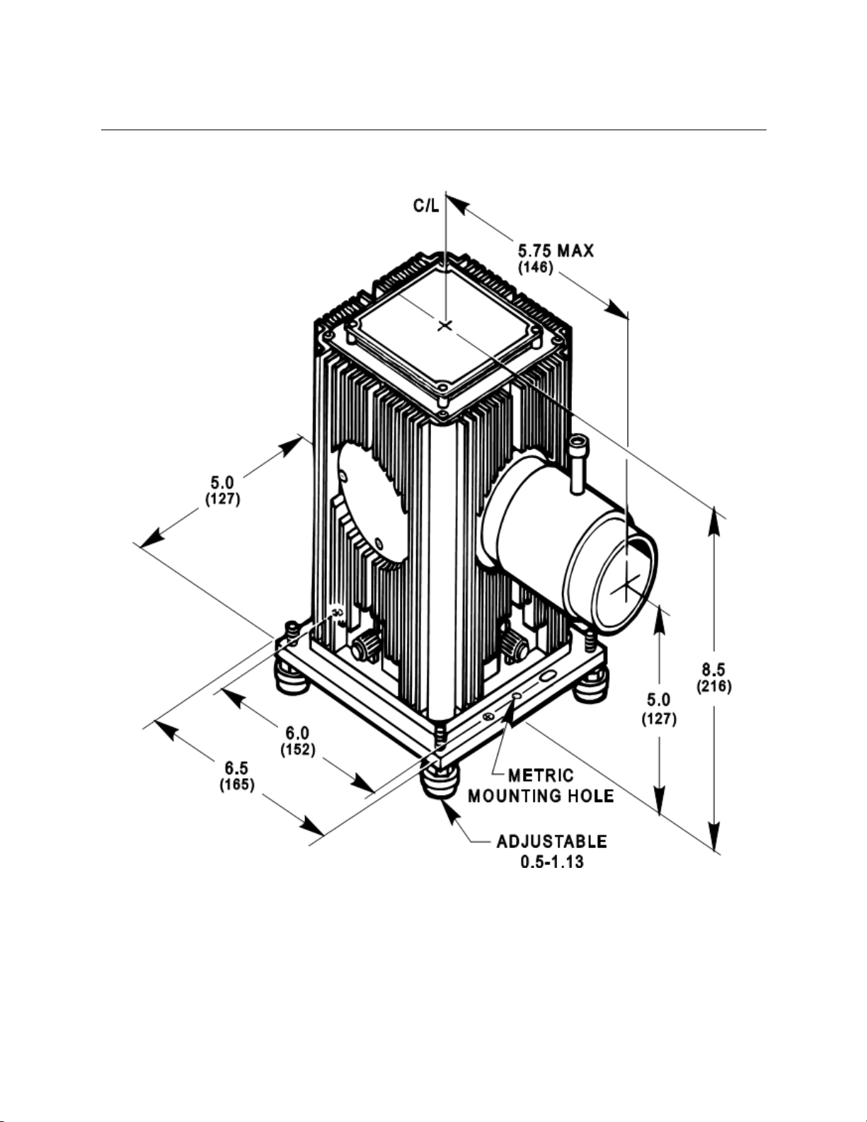
3.4 MOUNTING
The 60000 comes with four leveling feet. The feet allow 0.63-inch (16 mm) height adjustment. To
mount directly to inch or metric optical tables, remove the feet and use the appropriate mounting
holes. This puts the optical axis at 5.0 inches (127 mm) above the table. See

M60000
SERIES Q CONVECTIVE LAMP HOUSING
14
Figure 4 : Dimensional
M60000
SERIES Q CONVECTIVE LAMP HOUSING
15
4. CONFIGURATION OPTIONS AND ACCESSORIES
4.1 INTERFACE KITS
You can operate arc, quartz tungsten halogen, deuterium lamps, and IR sources in the Series Q
Housing by changing the interface kit and socket adapter. Table 1 list the appropriate kits and
socket adapters for each source.
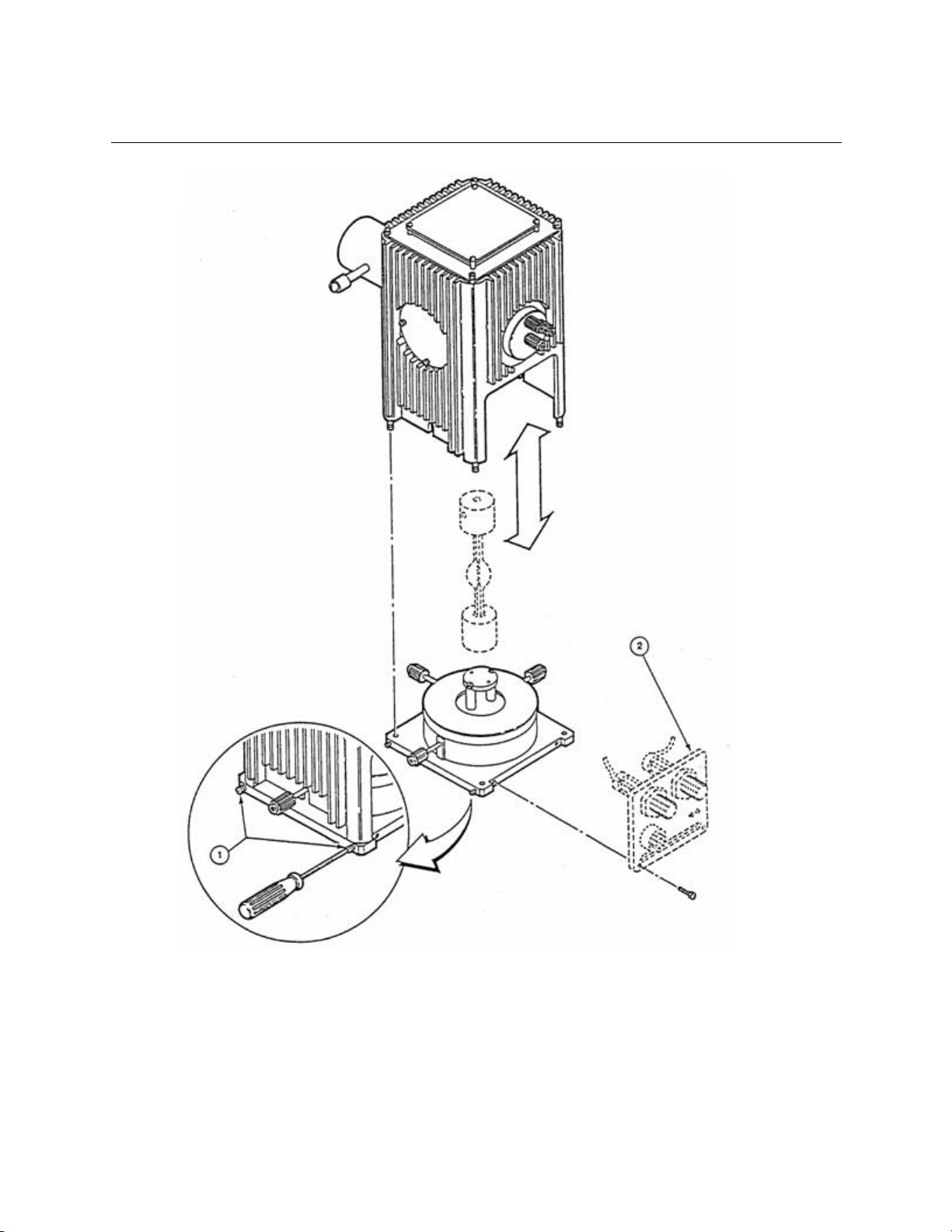
All kits have interface plates similar to the legacy model 60010 shown in Figure 5 for arc lamps ;
they are mounted as follows:
1. Partially loosen the (4) retaining screws, #1, and remove the upper housing shell by sliding it
upward.
2. Secure the interface plate, #2, with the (2) socket head cap screws in the recess of the base,
as shown in Figure 5.
3. Follow the specific instructions on the following pages for each interface kit lamp and socket
adapter listed below:
Table 2:
Interface Kit
Model Number
Page Number
DC Arc Lamps
60010 (Legacy)
17
DC Arc Lamps
60025****
21
Pulsed Arc Lamps
66015, 66016
34
Pulsed Xe 5 J
66017
17
QTH and IR
60020 (Legacy)
25
DC Deuterium
60023
30
Pulsed Deuterium
60024 (Legacy)
32
QTH and IR
60090****
36
DC Deuterium
60093****
27
**** CE marked Interface kit.
Note: If you are installing an Arc Lamp, be sure to observe proper orientation as shown in
Figure 7.
4. Lower the upper housing shell onto the base making sure the housing opening slides onto
the interface plate, and the upper shell tabs "trap" the plate.
5. Insert the (4) grooved studs of the upper housing shell into the base and secure it by
fastening the (4) retaining screws, #1.
Cable connections from the interface kit to the power supply are covered in the Interface Kit
Manuals.
M60000
SERIES Q CONVECTIVE LAMP HOUSING
16
Figure 5 : Mounting ArcLamp Interface to SeriesQ Housing

M60000
SERIES Q CONVECTIVE LAMP HOUSING
17
5. ARC LAMP KIT MODEL 60010, 66017
Arc lamp interface kit, Model 60010 & 66017.
Socket adapter for:
100W Hg use Model 60012
50W Hg use Model 60013
75W Xe use Model 60014
100W Xe use Model 60014
0.5 J Large Bulb XE use Model 60019
To install these components and to make electrical connections, follow the stepslisted below:
Interface Panel #60010 is designed for internal electricalconnectionsto 75-Watt and100-Watt Xenon
Lamps and 50 and 100-Watt Mercury Lamps. Interface Panel #66017 is designed for internal electrical
connections to .5 J Large Bulb XE Flash lamp.
5.1 INSTALLATION OF ARC LAMP INTERFACE KIT
(See Figure 5)
1. Remove the Q-Housing shell by following the instructions in 4.1 step 1
2. Place panel, item 2, on the recessed side of the XYZ positioner base.
3. Secure panel, item 2, with (2) screws #6-32 x 3/8, item 2 (enclosed).
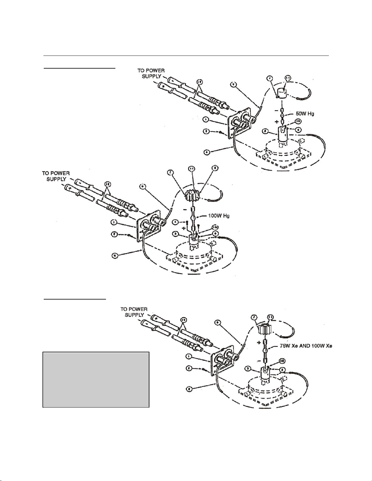
5.2 INSTALLATION OF SOCKET ADAPTERS AND ARC LAMPS
(See Figure 6)
1. Install bottom socket adapter, item 3, using (2) screws #4-40 x 1/2, item 4 (enclosed).
For 100W Hg use Model 60012 Socket Adapter
For 50W Hg use Model 60013 Socket Adapter
For 75W Xe use Model 60014 Socket Adapter
For100W Xe use Model 60014
For 0.5 J Large Bulb Xe use Model 60019 Socket Adapter
2. Install the bottom of the appropriate lamp into this terminal, secure the lamp using screw #4-
40, item 5. (Use Allen wrench supplied with the Q-Housing, basic unit.)
3. Install the top terminal, item 6, on the top of the arc lamp. Secure top terminal, item 6, using
set screw #4-40, item 7
Note: All top and bottom terminals have labels for identification purposes, and the lamp must
be in the correct orientation to avoid immediate damage. See Figure 7 to help identity the
lamp.
5.3 ELECTRICAL CONNECTIONS
1. Connect the cable, item 8, to the bottom terminal, item 3. Secure the contact using the
socket hd cap screw #4-40, item 10.
2. Connect the cable, item 9, to the top terminal, item 6. Secure the contact using the socket hd
cap screw #4-40, item 11.
3. Connect two H/V cables (negative and positive), item 12 to the appropriate connectors on the
panel, item 1. Follow mark-up instructions on the exterior panel for polarity of the appropriate
lamp.
M60000
SERIES Q CONVECTIVE LAMP HOUSING
18
FOR MERCURY LAMPS:
FOR XENON LAMPS:
Figure 6 : Interface Kit 60010
NOTE
MAKE SURE ALL ELECTRICAL
CABLES ARE PROPERLY CONNECTED;
POSITIVE TO POSITIVE; NEGATIVE TO
NEGATIVE AND THAT THE LAMP
TERMINALS ARE CORRECTLY
ORIENTED AS SHOWN IN THE
ILLUSTRATIONS.

M60000
SERIES Q CONVECTIVE LAMP HOUSING
19
Figure 7 : Arc LampOrientation
M60000
SERIES Q CONVECTIVE LAMP HOUSING
20
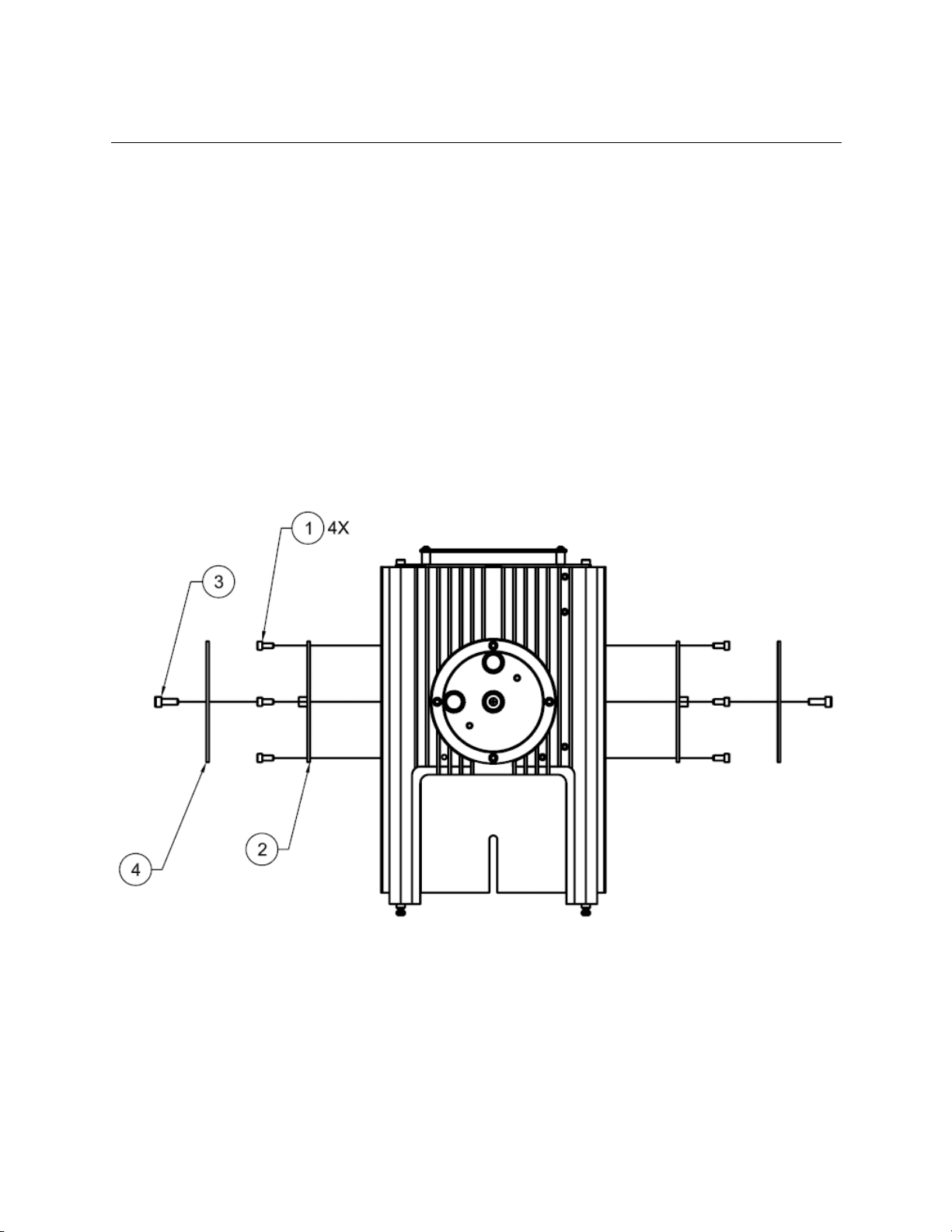
5.4 INSTALLATION OF VENTS
(See Figure 8)
1. Remove cover plates, item 1, from unused ports on sides of housing. Save the cover plates
for future use with other interface kits should your application change.
2. Attach vent plate, item 2, using 4 screws removed from cover plate in step 1.
3. Attach light shield, item 4, using (1) screw #6-32 x 3/8, item 3
5.5 REASSEMBLE Q-HOUSING SHELL
Continue with the instructions of section 4.1 steps 4 and 5 to complete the installation.
Figure 8 : SeriesQ-Housing with Vents
This manual suits for next models
1
Table of contents
Popular Industrial Electrical manuals by other brands


Comcast
Comcast 580A manual

M-system
M-system M3-UNIT Series operating manual

Murata
Murata GRM0335C1E430GA01 Series Reference sheet

Schrack
Schrack LTZ40002 Series instruction manual

Murata
Murata GJM1555C1H6R8WB01 Series Reference sheet

Control Techniques
Control Techniques Unidrive Size 2 Installation sheet