NexSysLink SAE J1939 User manual

Fax (603) 753-6201
Toll-free 800-451-8255
(603) 753-6362
Penacook, NH 03303
88 Village Street
Instrument Company, Inc.
Beede Electrical
Contact Beede
W W W .BEEDE . C O M
548941 A • 09.13.11© 2011, Beede Electrical Instrument Co., Inc.
2” CAN Display
Operation
Manual
Product Family
CAN Instruments
NexSysLink®

i
About � � � � � � � � � � � � � � � � � � � � � � � � � � � � � � � � � � � � � � � � � � � � � � � � � � � � � � � � � � � � � � � � � � � � � � � � � � iii
Scope � � � � � � � � � � � � � � � � � � � � � � � � � � � � � � � � � � � � � � � � � � � � � � � � � � � � � � � � � � � � � � � � � � � � � � � � � � iii
Precongured Instruments � � � � � � � � � � � � � � � � � � � � � � � � � � � � � � � � � � � � � � � � � � � � � � � � � � � � �iv
Stand-Alone and Master Node Congurations � � � � � � � � � � � � � � � � � � � � � � � � � � � � � � � � � � �iv
Product Outline Drawing � � � � � � � � � � � � � � � � � � � � � � � � � � � � � � � � � � � � � � � � � � � � � � � � � � � � � � � v
Menu Navigation � � � � � � � � � � � � � � � � � � � � � � � � � � � � � � � � � � � � � � � � � � � � � � � � � � � � � � � � � � � � � � � 1
Menu/Enter/Reset Switch � � � � � � � � � � � � � � � � � � � � � � � � � � � � � � � � � � � � � � � � � � � � � � � � � � � � � � � � � � � � � � � 1
Up Switch � � � � � � � � � � � � � � � � � � � � � � � � � � � � � � � � � � � � � � � � � � � � � � � � � � � � � � � � � � � � � � � � � � � � � � � � � � � � � � 1
Down Switch � � � � � � � � � � � � � � � � � � � � � � � � � � � � � � � � � � � � � � � � � � � � � � � � � � � � � � � � � � � � � � � � � � � � � � � � � � � 1
Switch Icon Conventions� � � � � � � � � � � � � � � � � � � � � � � � � � � � � � � � � � � � � � � � � � � � � � � � � � � � � � � � � � � � � � � � 1
Selection Arrow Cursor � � � � � � � � � � � � � � � � � � � � � � � � � � � � � � � � � � � � � � � � � � � � � � � � � � � � � � � � � � � � � � � � � 2
Menu Scrolling Icons� � � � � � � � � � � � � � � � � � � � � � � � � � � � � � � � � � � � � � � � � � � � � � � � � � � � � � � � � � � � � � � � � � � � 2
Blinking Bar Cursor � � � � � � � � � � � � � � � � � � � � � � � � � � � � � � � � � � � � � � � � � � � � � � � � � � � � � � � � � � � � � � � � � � � � � 3
Start-up Routine � � � � � � � � � � � � � � � � � � � � � � � � � � � � � � � � � � � � � � � � � � � � � � � � � � � � � � � � � � � � � � � � 4
Default CAN Parameter Screen � � � � � � � � � � � � � � � � � � � � � � � � � � � � � � � � � � � � � � � � � � � � � � � � � � 4
Viewing CAN Parameters � � � � � � � � � � � � � � � � � � � � � � � � � � � � � � � � � � � � � � � � � � � � � � � � � � � � � � � 4
Main Menu � � � � � � � � � � � � � � � � � � � � � � � � � � � � � � � � � � � � � � � � � � � � � � � � � � � � � � � � � � � � � � � � � � � � � 4
Maintenance Hours or Vehicle Trip � � � � � � � � � � � � � � � � � � � � � � � � � � � � � � � � � � � � � � � � � � � � � � � � � � � � � � 5
Faults Active� � � � � � � � � � � � � � � � � � � � � � � � � � � � � � � � � � � � � � � � � � � � � � � � � � � � � � � � � � � � � � � � � � � � � � � � � � � � 6
Viewing Active Faults � � � � � � � � � � � � � � � � � � � � � � � � � � � � � � � � � � � � � � � � � � � � � � � � � � � � � � � � � � � � � � � � � � � 7
Warnings Active � � � � � � � � � � � � � � � � � � � � � � � � � � � � � � � � � � � � � � � � � � � � � � � � � � � � � � � � � � � � � � � � � � � � � � � � 8
Viewing Active Warnings� � � � � � � � � � � � � � � � � � � � � � � � � � � � � � � � � � � � � � � � � � � � � � � � � � � � � � � � � � � � � � � � 9
Faults Stored � � � � � � � � � � � � � � � � � � � � � � � � � � � � � � � � � � � � � � � � � � � � � � � � � � � � � � � � � � � � � � � � � � � � � � � � � �10
Alarms � � � � � � � � � � � � � � � � � � � � � � � � � � � � � � � � � � � � � � � � � � � � � � � � � � � � � � � � � � � � � � � � � � � � � � � � � � � � � � � �11
Alarms Menu� � � � � � � � � � � � � � � � � � � � � � � � � � � � � � � � � � � � � � � � � � � � � � � � � � � � � � � � � � � � � � � � � � � � �12
Enabling/Disabling Alarms � � � � � � � � � � � � � � � � � � � � � � � � � � � � � � � � � � � � � � � � � � � � � � � � � � � � � � �13
Viewing Alarms � � � � � � � � � � � � � � � � � � � � � � � � � � � � � � � � � � � � � � � � � � � � � � � � � � � � � � � � � � � � � � � � � �14
Alarm Conguration� � � � � � � � � � � � � � � � � � � � � � � � � � � � � � � � � � � � � � � � � � � � � � � � � � � � � � � � � � � � � �15
Adding an Alarm or Alarms � � � � � � � � � � � � � � � � � � � � � � � � � � � � � � � � � � � � � � � � � � � � � � � � � � � � � � �16
Editing Alarms � � � � � � � � � � � � � � � � � � � � � � � � � � � � � � � � � � � � � � � � � � � � � � � � � � � � � � � � � � � � � � � � � � �18
Deleting Alarms � � � � � � � � � � � � � � � � � � � � � � � � � � � � � � � � � � � � � � � � � � � � � � � � � � � � � � � � � � � � � � � � �19
Mute � � � � � � � � � � � � � � � � � � � � � � � � � � � � � � � � � � � � � � � � � � � � � � � � � � � � � � � � � � � � � � � � � � � � � � � � � � � � � � � � � �20
Setup Menu � � � � � � � � � � � � � � � � � � � � � � � � � � � � � � � � � � � � � � � � � � � � � � � � � � � � � � � � � � � � � � � � � � � 21
Backlight � � � � � � � � � � � � � � � � � � � � � � � � � � � � � � � � � � � � � � � � � � � � � � � � � � � � � � � � � � � � � � � � � � � � � � � � � � � � � �22
Lamp On & Lamp O � � � � � � � � � � � � � � � � � � � � � � � � � � � � � � � � � � � � � � � � � � � � � � � � � � � � � � � � � � � � �22
Setting Units � � � � � � � � � � � � � � � � � � � � � � � � � � � � � � � � � � � � � � � � � � � � � � � � � � � � � � � � � � � � � � � � � � � � � � � � � �23
Popups Notication Screens � � � � � � � � � � � � � � � � � � � � � � � � � � � � � � � � � � � � � � � � � � � � � � � � � � � � � � � � � � �24
Setting Popups � � � � � � � � � � � � � � � � � � � � � � � � � � � � � � � � � � � � � � � � � � � � � � � � � � � � � � � � � � � � � � � � � � � � � � � �25
Display � � � � � � � � � � � � � � � � � � � � � � � � � � � � � � � � � � � � � � � � � � � � � � � � � � � � � � � � � � � � � � � � � � � � � � � � � � � � � � � �26
1 or 2 Parameter Display� � � � � � � � � � � � � � � � � � � � � � � � � � � � � � � � � � � � � � � � � � � � � � � � � � � � � � � � � �27
Set Contrast� � � � � � � � � � � � � � � � � � � � � � � � � � � � � � � � � � � � � � � � � � � � � � � � � � � � � � � � � � � � � � � � � � � � � �28
Video Mode Formats � � � � � � � � � � � � � � � � � � � � � � � � � � � � � � � � � � � � � � � � � � � � � � � � � � � � � � � � � � � � �29
Set Video � � � � � � � � � � � � � � � � � � � � � � � � � � � � � � � � � � � � � � � � � � � � � � � � � � � � � � � � � � � � � � � � � � � � � � � �30
Trip Mode � � � � � � � � � � � � � � � � � � � � � � � � � � � � � � � � � � � � � � � � � � � � � � � � � � � � � � � � � � � � � � � � � � � � � � � � � � � � �31
Alarm Output � � � � � � � � � � � � � � � � � � � � � � � � � � � � � � � � � � � � � � � � � � � � � � � � � � � � � � � � � � � � � � � � � � � � � � � � �32
Firmware Information� � � � � � � � � � � � � � � � � � � � � � � � � � � � � � � � � � � � � � � � � � � � � � � � � � � � � � � � � � � � � � � � � �33
Implementation of SAE J1939 Parameters � � � � � � � � � � � � � � � � � � � � � � � � � � � � � � � � � � � � � � 34
Parameter Icons & Descriptions � � � � � � � � � � � � � � � � � � � � � � � � � � � � � � � � � � � � � � � � � � � � � � � � 35
Menu Navigation Icon Descriptions � � � � � � � � � � � � � � � � � � � � � � � � � � � � � � � � � � � � � � � � � � � � 36
Table of Contents
NexSysLink®2" Stand-Alone CAN Display Operation Manual SAE J1939

ii
List of Figures
Figure 1-1: Menu Scrolling and Option Selection � � � � � � � � � � � � � � � � � � � � � � � � � � � � � � � � 2
Figure 1-2: Blinking Bar Cursor � � � � � � � � � � � � � � � � � � � � � � � � � � � � � � � � � � � � � � � � � � � � � � � � � 3
Figure 1-3: Accessing the Main Menu � � � � � � � � � � � � � � � � � � � � � � � � � � � � � � � � � � � � � � � � � � � 4
Figure 1-4: Accessing and Resetting Maintenance Hours and Vehicle Trip Logs � � � 5
Figure 1-5: Fault Notication and Information Screens � � � � � � � � � � � � � � � � � � � � � � � � � � � 6
Figure 1-6: Viewing Active Faults � � � � � � � � � � � � � � � � � � � � � � � � � � � � � � � � � � � � � � � � � � � � � � � 7
Figure 1-7: Warning Notication and Information Screens � � � � � � � � � � � � � � � � � � � � � � � 8
Figure 1-8: Viewing Active Warnings � � � � � � � � � � � � � � � � � � � � � � � � � � � � � � � � � � � � � � � � � � � � 9
Figure 1-9: Faults Stored Information Screens � � � � � � � � � � � � � � � � � � � � � � � � � � � � � � � � � � 10
Figure 1-10: Alarms Menu Functions � � � � � � � � � � � � � � � � � � � � � � � � � � � � � � � � � � � � � � � � � � � 12
Figure 1-11: Enabling/Disabling Alarms � � � � � � � � � � � � � � � � � � � � � � � � � � � � � � � � � � � � � � � � 13
Figure 1-12: Alarm Screen Details � � � � � � � � � � � � � � � � � � � � � � � � � � � � � � � � � � � � � � � � � � � � � � 14
Figure 1-13: Viewing Alarms � � � � � � � � � � � � � � � � � � � � � � � � � � � � � � � � � � � � � � � � � � � � � � � � � � � 14
Figure 1-14: Add & Edit Alarm CAN Parameter Screen Details � � � � � � � � � � � � � � � � � � � 15
Figure 1-15: Menu Prompt Sequence with No Congured Alarms � � � � � � � � � � � � � � � 16
Figure 1-16: Menu Prompt Sequence with Previously Congured Alarms � � � � � � � 17
Figure 1-17: Editing an Alarm � � � � � � � � � � � � � � � � � � � � � � � � � � � � � � � � � � � � � � � � � � � � � � � � � � 18
Figure 1-18: Deleting an Alarm � � � � � � � � � � � � � � � � � � � � � � � � � � � � � � � � � � � � � � � � � � � � � � � � 19
Figure 1-19: Muting Faults, Warnings & Alarms � � � � � � � � � � � � � � � � � � � � � � � � � � � � � � � � � 20
Figure 1-20: Setup Menu Functions � � � � � � � � � � � � � � � � � � � � � � � � � � � � � � � � � � � � � � � � � � � � 21
Figure 1-21: Setting Backlight Intensity � � � � � � � � � � � � � � � � � � � � � � � � � � � � � � � � � � � � � � � � 22
Figure 1-22: Setting Units � � � � � � � � � � � � � � � � � � � � � � � � � � � � � � � � � � � � � � � � � � � � � � � � � � � � � 23
Figure 1-23: Popup Fault, Warning & Alarm Screens � � � � � � � � � � � � � � � � � � � � � � � � � � � � 24
Figure 1-24: Setting Popup Status � � � � � � � � � � � � � � � � � � � � � � � � � � � � � � � � � � � � � � � � � � � � � 25
Figure 1-25: Display Menu � � � � � � � � � � � � � � � � � � � � � � � � � � � � � � � � � � � � � � � � � � � � � � � � � � � � � 26
Figure 1-26: 1 and 2 CAN Parameter Display Formats � � � � � � � � � � � � � � � � � � � � � � � � � � � 27
Figure 1-27: Setting 1 or 2 Parameter Display Lines � � � � � � � � � � � � � � � � � � � � � � � � � � � � � 27
Figure 1-28: Setting LCD Contrast � � � � � � � � � � � � � � � � � � � � � � � � � � � � � � � � � � � � � � � � � � � � � � 28
Figure 1-29: Video Mode Formats � � � � � � � � � � � � � � � � � � � � � � � � � � � � � � � � � � � � � � � � � � � � � � 29
Figure 1-30: Setting LCD Background Color Scheme (Video Mode) � � � � � � � � � � � � � � 30
Figure 1-31: Setting Hours or Miles for Main Menu Display � � � � � � � � � � � � � � � � � � � � � 31
Figure 1-32: Setting Alarm Output Pin Status � � � � � � � � � � � � � � � � � � � � � � � � � � � � � � � � � � � 32
Figure 1-33: Viewing Firmware Revision � � � � � � � � � � � � � � � � � � � � � � � � � � � � � � � � � � � � � � � � 33
NexSysLink®2" Stand-Alone CAN Display Operation Manual SAE J1939

iii
• About
The 2" Stand-Alone CAN Display instrument is a member of the Beede
NexSysLink® CAN instruments product family�
This instrument directly reads SAE J1939 compliant CAN messages and
displays the message information on a sunlight visible, transective dot-
matrix LCD� Like all NexSysLink® instruments, this product eliminates the
need for a translation “black box” between an ECM/ECU and the instrument
itself making wiring and installation simple and fast�
Three discrete alert LEDs provide users with visual notication of engine/
vehicle/vessel parameter faults, warnings and malfunctions�
Built-in, sealed, tactile switches allow users to easily navigate the intuitive
menu driven user interface� The integration of the switches also reduces
wiring to further reduce installation time and costs; essentially providing a
plug-and-play product�
Although designed to "stand-alone", the instrument may be used
in conjunction with other NexSysLink® instruments to monitor your
equipment�
• Scope
This manual describes how to navigate the LCD interface and use the many
features the instrument provides� Although the interface is intuitive and
easy to navigate, this operation manual provides users with a resource to
realize the full potential and capabilities of the instrument�
Covered in this manual are display options, menu navigation and menu
function usage�
Although some wiring connections are noted for easy reference, this
manual does not cover complete installation mounting and wiring
requirements� Please refer to the installation instruction sheet for proper
installation�
NexSysLink®2" Stand-Alone CAN Display Operation Manual SAE J1939

iv
• Precongured Instruments
Some instruments are precongured at the factory to individual OEM
specications to best meet the needs of the application and end user�
Precongured features include but may not be limited to alarm
conguration, single or dual line display and backlight intensity�
Precongured features are easily modied to satisfy personal preferences�
• Stand-Alone and Master Node Congurations
The instrument is primarily designed to "stand-alone" in applications
where ease of use, limited space and simple installation are critical
criteria in choosing the type of engine/vehicle/vessel monitoring
electronics�
In order to satisfy a wide range of application demands, the hardware
of the 2" CAN Display can be factory congured to drive a maximum
of 16 Beede NexSysLink® Slave Node Instruments (SNI) or Analog
Slave Node Instruments (ASNI)�
The ability to connect with ASNI gauges expands the instruments
capabilities to display analog inputs such as fuel level or air pressure�
When factory congured to drive Beede NexSysLink® SNI or
ASNI gauges, Pin 4 of the 6 pin connector is used for serial data
communication among the instruments�
NexSysLink®2" Stand-Alone CAN Display Operation Manual SAE J1939

vNexSysLink®2" Stand-Alone CAN Display Operation Manual SAE J1939
© 2011 Beede Electrical Instrument Co., Inc.
• Product Outline Drawing
Mounting hole size:
Ø2.125±.015”
(Ø53.98±0.38mm)
Mounting hardware torque:
6 lb-in
(0.68 N-m) max.
Refer to the appropriate
Beede installation instruction
sheet for complete installation
requirements.
Dimensions shown are in inches.
6 Pin Connector Wiring Table
Connection
Name
Battery +
Pin
Number
1
Ground2
Switched Output3
Lamp (B+) or Serial Data4
CAN-H5
CAN-L6

1
NexSysLink®2" Stand-Alone CAN Display Operation Manual SAE J1939
© 2011 Beede Electrical Instrument Co., Inc.
• Menu Navigation
Menu navigation is accomplished through three built-in momentary switches� The switch functions are
MENU/ENTER/RESET, UP and DOWN�
• Menu/Enter/Reset Switch
As its name suggests, this switch serves several purposes when navigating the user interface� The
function depends upon the context of the menu option but is labeled ENTER on the instrument�
Menu Function: Pressing and holding this switch for approximately three seconds when any parameter
screen is displayed brings up the main menu�
Enter Function: Pressing and releasing this switch provides enter functionality when the operator is
required to choose a menu item, parameter, or value�
Reset Function: Pressing and holding this switch resets the selected trip miles or maintenance hour
value to zero�
• Up Switch
Pressing and releasing the Up switch scrolls up through the CAN parameter list, menu choices or
increases a value one item/unit at a time�
Pressing and holding the Up switch continuously scrolls up through the CAN parameter list, menu
choices or increases a value until the end of the menu choices or maximum value is reached�
• Down Switch
The Down switch functions identical to the Up switch with the exception that its direction for all lists,
menu choices and values is down or decreasing�
• Switch Icon Conventions
Throughout this manual, icons are used to indicate actions required by the user to navigate the menus�
Below are descriptions and the corresponding action to be taken when they appear�
Press and release Menu/Enter/Reset switch icon�
The presence of this icon in the manual indicates when to press and release
the Menu/Enter/Reset switch�
Press and hold Menu/Enter/Reset switch icon�
The presence of this icon in the manual indicates when to press and hold
the Menu/Enter/Reset switch for approximately three seconds�
Press Up switch icon�
The presence of this icon in the manual indicates when to press and release the Up switch�
Users may also choose to press and hold the Up switch if necessary�
Press Down switch icon�
The presence of this icon in the manual indicates when to press and release the Down
switch� Users may also choose to press and hold the Down switch if necessary�

2NexSysLink®2" Stand-Alone CAN Display Operation Manual SAE J1939
© 2011 Beede Electrical Instrument Co., Inc.
• Menu Navigation (Continued)
The user interface contains various icons and indicators to guide users for item selection and/or input
while navigating the menus� The selection arrow, menu scrolling icon and blinking bar cursors appear
frequently throughout the menus�
• Selection Arrow Cursor
The selection arrow cursor, shown at left, identies adjacent menu items as the current
selection� Pressing the Enter switch selects the menu item/function or value adjacent to
the arrow cursor�
Pressing and releasing an Up or Down switch moves the selection arrow up or down a
menu list one item at a time until the beginning or end of the list is reached� Pressing and
holding the Up or Down switch continuously moves the selection arrow up and down a menu list until
the switch is released or the beginning or end of the list is reached�
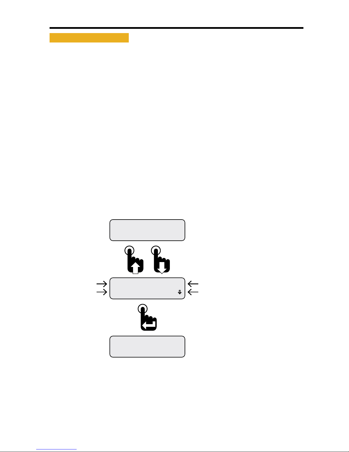
• Menu Scrolling Icons
A menu scrolling icon appears in the lower right corner of the display to
indicate if more menu options appear only above, only below or above and
below the menu option or options currently displayed�
Figure 1-1: Menu Scrolling and Option Selection
Menu scrolling icon indicating
more options appear above
and below those shown.
Selection Arrow Cursor
Warnings Acve
Faults Active
Menu scrolling icon indicating
more options appear below
those shown.
Selection Arrow Cursor
Faults Active
Maintenance Hours
First Main Menu Screen
Note: Many menu screen diagrams
in this manual only show the rst
two options of the entire menu.
If more than two options are
available within a menu, a listing
of all the options will appear
below the menu diagram.
Complete Main Menu
Function List
Maintenance Hours
Faults Active
Warnings Active
Faults Stored
Alarms
Mute Audio Alarm
Setup
Information
Exit
To select option
adjacent to
selection arrow cursor
To scroll up and down
a menu option list

3
NexSysLink®2" Stand-Alone CAN Display Operation Manual SAE J1939
© 2011 Beede Electrical Instrument Co., Inc.
• Blinking Bar Cursor
A blinking bar cursor appearing beneath a numeric value or CAN parameter indicates the item may be
changed by pressing or pressing and holding either the Up or Down switches�
When a numeric value appears above a blinking bar cursor, pressing or pressing and holding the Up or
Down switch increases or decreases the value until the maximum value limits are reached�
When a CAN parameter appears above a blinking bar cursor, pressing or pressing and holding either the
Up or Down switch scrolls through the list of CAN parameters until the end of the list is reached�
Figure 1-2: Blinking Bar Cursor
0 A
A1 Baery Current
Blinking Bar Cursor
located under amperage value
0.0 bar
A1 Coolant Pressure
Blinking Bar Cursor
located under parameter name
Pressing the Up or Down switch
changes the CAN parameter or value until the
end of the list or limits of the value range is reached.
Pressing the Enter switch when
the desired parameter or value is
displayed accepts the parameter or value.

4NexSysLink®2" Stand-Alone CAN Display Operation Manual SAE J1939
© 2011 Beede Electrical Instrument Co., Inc.
• Start-up Routine
Upon Instrument start-up, the three alert LEDs will ash then the Beede logo followed by the SAE logo
appear for approximately three seconds�
• Default CAN Parameter Screen
After completion of the start-up routine, the Engine Hours CAN parameter appears� If power was
removed from the instrument with a dierent parameter displayed, Engine Hours will appear when
power is reapplied to the instrument�
• Viewing CAN Parameters
All actively broadcast SAE J1939 CAN parameters implemented by the instrument are available for
viewing� See "Implementation of SAE J1939 Parameters" on page 34� Press the Up or Down switch to
nd and view the desired parameter� The displayed parameter will not time out and remains displayed
until a dierent parameter is selected for viewing or power is removed from the instrument�
• Main Menu
The Main Menu contains functions to congure the LCD (Liquid Crystal Display), set alarms or view ECM
faults and warnings� Access the Main Menu by pressing and holding the Menu/Enter/Reset switch for
approximately three seconds while any CAN parameter screen is displayed�
Like all menus with multiple functions/options, only the rst two Main Menu functions/options appear
on the screen� Access the other functions/options by scrolling down the menu list using the Down
switch� Use the Up switch to scroll back up the Main Menu function/option list�
The Main Menu and all the functions within it except Maintenance Hours and Vehicle Trip functions will
display for approximately 30 seconds if no user activity is detected� The previously displayed parameter
reappears after 30 seconds of inactivity�
Figure 1-3: Accessing the Main Menu
Faults Active
Maintenance Hours
Engine Hours
1049.3
* Either Maintenance Hours or
Vehicle Trip appears as the rst
Main Menu function depending
upon the Main Menu-Setup-Trip Mode
conguration.
Main Menu-Setup-Trip-Hours
displays Maintenance Hours.
Main Menu-Setup-Trip-Distance
displays Vehicle Trip.
Complete Main Menu
Function List
*Maintenance Hours
Faults Active
Warnings Active
Faults Stored
Alarms
Mute Audio Alarm
Mute-Temporary
Setup
Information
Exit
To select a Main Menu
function adjacent to the
selection arrow cursor
To scroll up and down
the Main Menu list
First Main Menu Screen
Parameter Display Screen.
Engine Hours shown as an
example only.

5
NexSysLink®2" Stand-Alone CAN Display Operation Manual SAE J1939
© 2011 Beede Electrical Instrument Co., Inc.
• Maintenance Hours or Vehicle Trip
Depending upon the conguration of the instrument, either Maintenance Hours or Vehicle Trip appears
as the rst Main Menu function� See "Trip Mode" on page 31 for setting hours or trip as the rst Main
Menu function�
The instrument provides two resettable maintenance hour and vehicle trip logs� The Maintenance
Hours or Vehicle Trip function allows users to view and reset any of the hour or trip logs�
Figure 1-4: Accessing and Resetting Maintenance Hours and Vehicle Trip Logs
Exit
Return
308.0Hour2
0.0Hour1
308.0Hour2
1049.3Hour1
308.0Hour2
1049.3Hour1
Faults Active
Maintenance Hours
Engine Hours
1049.3
Scroll down to place the selection arrow cursor next
to the Return option then press the Enter switch
to access the Main Menu.
Scroll down to place the selection arrow cursor next
to the Exit option then press the Enter switch to
return to the last displayed CAN parameter screen.
Hour1 log reset to zero.
Hour2 log may be reset by moving the selection
arrow cursor down to Hour2 log then pressing and
holding the Enter switch.
Selection arrow cursor appears next to Hour1 log.
Press and hold Enter switch to reset Hour1 log or press
the Down switch to place selection arrow cursor next
to Hour2 log.
Maintenance hour log screen appears.
Press Down switch to select an hour log.
Note: Maintenance Hour and trip log displays do not
time out after 30 seconds and return the last
CAN parameter displayed like most menu displays.
First Main Menu screen appears with the selection
arrow cursor next to Maintenance Hours.
Press the Enter switch to display maintenance hour logs.
Note: Instrument may be congured for vehicle trip
instead of maintenance hours.
With a CAN parameter displayed, press and
hold the Enter switch to open the Main Menu.
Engine Hours CAN parameter shown as an example only.

6NexSysLink®2" Stand-Alone CAN Display Operation Manual SAE J1939
© 2011 Beede Electrical Instrument Co., Inc.
• Faults Active
Faults are an indicator of a severe vehicle problem as reported by the ECM/ECU that warrants stopping
the engine/vehicle/vessel� Users should consult the owners manual or a service technician to correct
the fault condition or conditions�
When a fault condition occurs, the instruments internal audible alarm and Fault LED are activated�
The internal audible alarm is temporarily muted by pressing the Enter switch�
An external audible device connected to output pin 3 of the six pin connector will also be muted if the
setup option Alarm Output, Main Menu-Setup-Alarm Output, is set to Audio� See "Alarm Output" on
page 32 to congure alarm output pin�
The Main Menu-Faults Active option allows users to view the parameter or parameters causing fault
notication� If popups for fault conditions is enabled, a fault notication screen appears� Refer to
"Setting Popups" on page 25�
The Faults Active function within the Main Menu allows users to view details for all currently active
faults�
Fault information includes the following:
DM1 (Diagnostic Message) for active faults or DM2 for stored faults
Fault number and total fault quantity, e�g�, 1 of 3
SPN (Suspect Parameter Number) numerically identies the parameter per the CAN protocol
FMI (Fault Mode Indicator) number to further identify the faults characteristic
Fault Name� Appears if the CAN parameter is implemented in the instruments rmware�
See"Implementation of SAE J1939 Parameters" on page 34
The active fault display will not time out after 30 seconds� Press the Enter switch to exit viewing faults
and return to the Faults Active option of the Main Menu�
Figure 1-5: Fault Notication and Information Screens
Eng Oil Pressure
DM1Fault 1of 1
SPN 100 FMI 3
DM1Fault 1of 1
FAULT
Pressing the Down switch displays
the fault name instead of the
SPN number.
Fault Notication Screen Appears
if Popups are Enabled.
Refer to Setting Popups.
Pressing the Enter switch
clears the fault notication
and returns the last displayed
CAN parameter.
Failure Mode Indicator
Fault number of total faults
Suspect Parameter Number
Diagnostic Mode Number
Parameter Name

7
NexSysLink®2" Stand-Alone CAN Display Operation Manual SAE J1939
© 2011 Beede Electrical Instrument Co., Inc.
• Viewing Active Faults
If a fault information screen is cleared after it initially appears and the fault is still active, users can view
all the active fault information screens by using the Faults Active function of the Main Menu, Main Menu-
Active Faults�
Figure 1-6: Viewing Active Faults
Warnings Active
Faults Active
Eng Oil Pressure
DM1Fault 1of 1
SPN 100 FMI 0
DM1Fault 1of 1
Warnings Active
Faults Active
Faults Active
Maintenance Hours
Engine Hours
1049.3
Pressing the Enter switch with any of the active fault
detail screens visible returns the selection arrow
cursor next to the Faults Active option within the
Main Menu.
Scrolling down shows the fault name instead of the
SPN number. If more than one fault is active, scroll
down to see the subsequent fault details.
The fault screen appears listing the number of faults
(1 of 1 in this example), SPN and FMI numbers.
Scroll down to view the fault parameter name.
With the selection arrow cursor next to the
Faults Active option, press the Enter switch to
begin viewing fault detailed information.
First Main Menu screen appears with selection
arrow cursor next to Maintenance Hours.
Press the Down switch to place the selection arrow
cursor next to the Faults Active option.
With a CAN parameter displayed, press and
hold the Enter switch to bring up the Main Menu.
Engine Hours parameter shown as an example only.
8NexSysLink®2" Stand-Alone CAN Display Operation Manual SAE J1939
© 2011 Beede Electrical Instrument Co., Inc.
• Warnings Active
Warnings are an indicator of a vehicle problem as reported by the ECM/ECU that does not warrant
immediately stopping the vehicle or vessel� Users should consult the owners manual or a service
technician to correct the warning condition or conditions�
When a warning condition occurs, the instruments internal audible alarm and Warn LED are activated�
The internal audible alarm may be temporarily muted by pressing the Enter switch�
An external audible device connected to output pin 3 of the six pin connector will also be muted if the
setup option Alarm Output, Main Menu-Setup-Alarm Output, is set to Audio� See "Alarm Output" on
page 32 to congure alarm output pin�
The Main Menu-Warnings Active option allows users to view the parameter or parameters causing the
warning� If popups for warning conditions is enabled, a warning notication screen appears� Refer to
"Setting Popups" on page 25�
The built-in audible device will sound when a warning condition occurs if the Mute setting, Main Menu-
Mute Audio Alarm, is not set to Permanent� See "Mute" on page 20 for enabling the internal audible
device�
The active warning display will not time out after 30 seconds� Press the Enter switch to exit viewing
warnings and return to the Warnings Active option of the Main Menu�
Figure 1-7: Warning Notication and Information Screens
Engine Hours
1049.3
WARNING
Eng Oil Pressure
Warning SPN 100
Pressing the Enter switch returns
the last displayed CAN parameter.
Engine Hours CAN parameter
shown as an example only.
A warning notication screen appears when
popups are enabled and a warning condition
occurs.
Refer to setting popups.
Menu Scroll Icon.
Appears only if more warnings
are present.
Suspect Parameter Number
Parameter Name
Warning Label

9
NexSysLink®2" Stand-Alone CAN Display Operation Manual SAE J1939
© 2011 Beede Electrical Instrument Co., Inc.
• Viewing Active Warnings
If a warning information screen is cleared after it initially appears and the warning is still active, users
can view all the active warning information screens by using the Warnings Active function of the Main
Menu, Main Menu-Warnings Active�
Figure 1-8: Viewing Active Warnings
Faults Stored
Warnings Active
EngOil Pressure
Warning SPN 100
Faults Stored
Warnings Active
Faults Active
Maintenance Hours
Engine Hours
1049.3
Pressing the Enter switch with any of the active
warnings detail screens visible returns the selection
arrow cursor next to the Warnings Active option
within the Main Menu.
The warning detail screen appears if at least one
warning is present. If multiple warnings are present,
the menu scroll down icon appears.
Scroll down to view other warnings or press the Enter
switch to return to the Warnings Active option of the
Main Menu.
Press the Enter switch with the selection arrow cursor
next to the Warnings Active option to view all current
system warnings.
First Main Menu screen appears with selection
arrow cursor next to Maintenance Hours.
Scroll down to place the selection arrow cursor
next to the Warnings Active option.
With a CAN parameter displayed, press and
hold the Enter switch to bring up the Main Menu.
Engine Hours parameter shown as an example only.

10 NexSysLink®2" Stand-Alone CAN Display Operation Manual SAE J1939
© 2011 Beede Electrical Instrument Co., Inc.
• Faults Stored
The instrument will display all DM2 (Diagnostic Mode) faults stored by the ECU� DM2 faults are
previously active diagnostic trouble codes�
Figure 1-9: Faults Stored Information Screens
Alarms
Faults Stored
Eng Oil Pressure
DM2 Fault 1of 1
SPN 100 FMI 3
DM2 Fault 1of 1
Alarms
Faults Stored
Faults Active
Maintenance Hours
Engine Hours
1049.3
Pressing the Enter switch with any of the stored faults
detail screens visible returns the selection arrow
cursor next to the Faults Stored option within the
Main Menu.
Scrolling down shows the fault name instead of the
SPN number if the parameter is implemented in the
instruments rmware.
If more than one stored fault is active, scroll down
to see the subsequent stored fault details.
The fault screen appears listing the number of stored
faults (1 of 1 in this example), SPN and FMI numbers.
Scroll down to view the fault parameter name.
With the selection arrow cursor next to
the Faults Stored option, press the Enter
switch to view stored faults.
First Main Menu screen appears with selection
arrow cursor next to Maintenance Hours.
Press the Down switch to place the selection arrow
cursor next to the Faults Stored option.
With a CAN parameter displayed, press and
hold the Enter switch to bring up the Main Menu.
Engine Hours parameter shown as an example only.

11
NexSysLink®2" Stand-Alone CAN Display Operation Manual SAE J1939
© 2011 Beede Electrical Instrument Co., Inc.
• Alarms
Alarms are user congured limits for CAN parameters used to alert operators when the parameter or
parameters exceeds those limits� Alarms help users protect a vehicle, vessel or equipment from damage
by providing an option to set operating notication limits for CAN parameters critical to the application�
A maximum of 15 parameters may be congured for alarm notication�
Note: Alarms are only a notication feature and do not disable or diminish the operation of a vehicle or
equipment�
Alarm settings are written to non-volatile memory and retained when power is removed from the
instrument�
If alarms are congured and enabled, a blinking "Bell" icons appears in the upper left corner of the
current CAN parameter display screen once a parameter exceeds the set alarm limits� If popups for
alarm conditions is enabled, an alarm notication screen appears� Refer to "Setting Popups" on page
25�
The built-in audible device will sound when an alarm occurs if the Mute setting, Main Menu-Mute Audio
Alarm, is not set to Permanent� See "Mute" on page 20 for enabling the internal audible device�
Parameter Display Screen with Alarm “Bell” Icon
Engine Hours
1049.3
ALARM
Pressing the Enter switch clears the alarm notication
screen and returns the last displayed CAN parameter.
A blinking bell icon appears in the upper left corner of
the screen to indicate the alarm condition is still active.
An alarm notication screen appears when popups
are enabled and an alarm condition occurs.
Refer to setting popups.

12 NexSysLink®2" Stand-Alone CAN Display Operation Manual SAE J1939
© 2011 Beede Electrical Instrument Co., Inc.
• Alarms Menu
The Main Menu-Alarms function allows users to enable alarm notication, view the parameter or
parameters causing the alarm, edit existing alarms and add new alarms�
Figure 1-10: Alarms Menu Functions
View Alarms
Alarms-Enabled
Mute Audio Alarm
Alarms
Alarms-Enabled (Disabled)
View Alarms
Edit Alarms
Return
Exit
Alarms Menu Function List.
Note: Pressing the Enter switch toggles between
Alarms Enabled and Alarms-Disabled.
The Alarms menu appears with the selection arrow
cursor next to the Alarms-Enabled or Disabled option.
Scroll down to view all Alarms menu functions.
From the Main Menu, scroll to place the selection
arrow cursor next to the Alarms option.
Press the Enter switch to open Alarms menu.
Alarm Menu function Summary:
Alarms-Enabled - Turns on all set alarms�
Alarms-Disabled - Turns o all set alarms�
View Alarms - Allows users to view all set alarm congurations�
Edit Alarms - Allows users to edit existing alarms, add new alarms or delete existing alarms�
Return - Brings users back to the Alarms option of the Main Menu�
Exit - Brings users back to the last displayed CAN parameter screen

13
NexSysLink®2" Stand-Alone CAN Display Operation Manual SAE J1939
© 2011 Beede Electrical Instrument Co., Inc.
• Enabling/Disabling Alarms
Alarms-Enabled/Disabled turns on or o notication when an alarm condition occurs� This function
does not delete alarms or their settings from the alarm list�
Enabling or disabling alarms is a toggle function� When the Alarm menu is opened the current setting,
enabled or disabled, is shown� To change the current setting, simply press the Enter switch�
To protect against operating the vehicle unaware of potentially damaging conditions, always use
caution when deciding to turn o alarm notication�
Figure 1-11: Enabling/Disabling Alarms
Exit
Return
View Alarms
Alarms-Disabled
View Alarms
Alarms-Enabled
Mute Audio Alarm
Alarms
Scroll down to place the selection arrow cursor next
to the Return option then press the Enter switch
to leave the Alarms menu and return to the Main Menu.
Scroll down to place the selection arrow cursor next
to the Exit option then press the Enter switch to
leave the Alarms menu and view the last displayed
CAN parameter.
After pressing the enter switch, Alarms-Disabled appears.
Pressing the Enter switch a second time will toggle back
to Alarms-Enabled.
Depending upon the previous conguration of the instrument,
the Alarms menu appears with either Alarms-Enabled or
Alarms-Disabled as the current setting.
This screen shows the instrument’s current alarm conguration
as enabled. Pressing the Enter switch toggles to Alarms-Disabled.
From the Main Menu, scroll to place the selection
arrow cursor next to the Alarms option.
Press the Enter switch to open the Alarms menu.

14 NexSysLink®2" Stand-Alone CAN Display Operation Manual SAE J1939
© 2011 Beede Electrical Instrument Co., Inc.
• Viewing Alarms
View Alarms allows users to scroll through all CAN parameters congured for alarm notication�
Users are shown the alarm number, parameter name, measured value for the parameter and the alarm
trigger conditions for the parameter�
Figure 1-12: Alarm Screen Details
510 psi
A1Eng Oil Pressure
Menu Scroll Icon.
Indicates scroll to view other
alarms or Alarms Menu options.
Parameter Name
Measured Parameter Value.
5 psi shown.
Alarm Number
User set alarm trigger value.
10 psi shown.
Trigger threshold direction indicator.
Lower than indicator shown.
Figure 1-13: Viewing Alarms
Exit
Return
510 psi
A1Eng Oil Pressure
Edit Alarms
View Alarms
View Alarms
Alarms-Enabled
Mute Audio Alarm
Alarms
If no activity is detected for 30 seconds while viewing alarms,
the previously displayed CAN parameter appears.
To manually stop viewing alarms, scroll down to place the
selection arrow cursor next to the Return option then press
the Enter switch to return to the Main Menu or select the Exit
option to view the last displayed CAN parameter.
The rst congured alarm is displayed.
The display shows the alarm number, CAN parameter name
(if implemented), current reading and alarm trigger settings
(Below 10 psi in this example).
Scroll down to view any additional alarms.
With the selection arrow cursor next to the View Alarms option,
press the Enter switch to view any current alarms.
Once in the Alarms menu, scroll down to place the selection
arrow cursor next to the View Alarms option.
From the Main Menu, scroll to place the selection
arrow cursor next to the Alarms option.
Press the Enter switch to open the Alarms menu.
Table of contents
Popular Measuring Instrument manuals by other brands

humotion
humotion SmarTracks Diagnostics v.3.16 Installation guide & user manual

schmersal
schmersal SRB 200X2 operating instructions

KYORITSU
KYORITSU KEW 2062 instruction manual

Endress+Hauser
Endress+Hauser Deltabar PMD78B operating instructions

Bosch
Bosch GLM 100 C Operating/safety instructions

Armada Technologies
Armada Technologies Pro400 TDR quick start guide

Alber
Alber UXTM installation guide

Green Digital Power-tech
Green Digital Power-tech BG1F-4 User & installation manual

EAS Electric
EAS Electric SDM630MCTV2 instruction manual

HBM
HBM T10F KF1 operating manual

Anton Paar
Anton Paar ViscoQC 300 Series Instruction Manual and Safety Information

Callaway
Callaway 200 S user manual


