NextWave Digital PVR-6990 User manual


HDTV RECEIVER / RECORDER
PVR-6990
Operating Instructions
Please read these operating instructions before using the product
PVR-6990_070710 2007.7.10 12:30 PM 페이지2 MI 2400-175-cmyk-1

1
01 .
Warnings
-
Warnings
Read Instructions : All the safety and operating instructions should be read before the product is operated.
Retain Instructions : The safety and operating instructions should be retained for future reference.
Heed Warnings : All warnings on the product and in the operating instructions should be adhered to.
Follow Instructions : All operation and use instructions should be followed.
Cleaning : Unplug this product fro the wall outlet before cleaning. Do not use liquid cleaners or aerosol
cleaner. Use a da p cloth for cleaning.
Attach ent : Do not use attach ents not reco ended by the product anufacturer as they ay cause
hazards.
The lightning flash with arrowhead symbol, within an equilateral triangle, is intended to
alert the user to the presence of uninsulated "dangerous voltage" within the product's
enclosure that may be of sufficient magnitude to constitute a risk of electric shock to
persons.
The exclamation point within an equilateral triangle is intended to alert the user to the
presence of important operating and maintenance (servicing instructions in the literature
accompanying the appliance.
The appliance is not intended for use by young children / infirm persons without
supervision.
Young children should be supervised to ensure that they do not play with the appliance.
To prevent electric shock do not use this (polarized plug with a receptacle or other outlet
unless the blades can be fully inserted to prevent blade exposure.
Change or modification not expressly approved by the party responsible for compliance
could void the factory warranty.
The apparatus shall not be exposed to dripping or splashing and that no objects filled
with liquids, such as vases, shall be placed on the apparatus.
The socket-outlet shall be installed near the equipment and shall be easily accessible.
WARNING : To prevent fire of shock hazard, do not expose this appliance to rain or moisture.
CAUTION :
1.
2.
3.
4.
5.
6.
Important Safeguard
PVR-6990_070710 2007.7.10 12:30 PM 페이지4 MI 2400-175-cmyk-1

Warnings
-
01 .
Warnings
2
7.
8.
9.
10.
11.
12.
13.
14.
15.
16.
17.
18.
19.
Water and Moisture : Do not use the product near water - for exa ple, near a bath tub, wash bowl, kitchen
sink, or laundry tub ; in a wet base ent ; or near a swi ing pool ; and the like.
Accessories : Do not place this product on an unstable table. The product ay fall, causing serious injury
to a child or adult, and serious da age to the product. Use only with a table reco ended by the
anufacturer, or sold with the product. Any ounting of the product should follow the anufacturer's
instructions, and should use a ounting accessory reco ended by the anufacturer.
A product and cart co bination should be oved with care. Quick stops, excessive force,
and uneven surface ay cause the product and cart co bination to overturn. Please refer
to picture on the right.
Ventilation-Slot and openings in the cabinet are provided for ventilation and to ensure reliable operation of
the product and to protect it fro overheating, and these openings ust not be blocked or covered. The
openings should never be blocked by placing the product on a bed, sofa, rug, or other si ilar surface. This
product should not be placed in a built-in installation such as a bookcase or rack unless proper ventilation
is provided or the anufacturer's instructions have been adhered to.
Power Sources : This product should be operated only fro the type of power source indicated on the
arking label. If you are not sure of the type of power supply to your ho e, consult your product dealer or
local power co pany. For products intended to operate fro battery power, or other sources, refer to the
operating instructions.
Polarization : This product ay be equipped with a polarized alternating-current line plug. This plug will fit
into the power outlet only one way. This is a safety feature. Do not defeat the safety purpose of the
polarized plug.
Power-Cord Protection : Power-supply cords should be routed so that they are not likely to be walked on or
pinched by ite s placed upon or against the , paying particular attention to cords at plugs, convenience
receptacles, and the point where they exit fro the product.
Lighting : For added protection for this product during a lighting stor , or when it is left unattended and
unused for long periods of ti e, unplug it fro the wall outlet and disconnect the antenna or cable syste .
This will prevent da age to the product due to lighting and power-line surges.
Power Lines : An outside antenna syste should not be located in the vicinity or overhead power lines or
other electric light or power circuits, or where it can fall into such power lines or circuits. When installing an
outside antenna syste , extre e care should be taken to keep fro touching such power lines or circuits
as contact with the ight be fatal.
Overloading : Do not overload wall outlets, extension cords, or integral convenience receptacles as this
can result in a risk of fire or electric shock.
Object and Liquid Entry : Never push objects of any kind into this product through opening as they ay
touch dangerous voltage points or short-out parts that could result in a fire or electric shock. Never spill
liquid of any kind on the product.
Servicing : Do not atte pt to service this product yourself as opening or re oving covers ay expose you
to dangerous voltage or other hazards. Refer all servicing to qualified service personnel.
Da age Requiring Service : Unplug this product fro the wall outlet and refer servicing to qualified service
personnel under the following conditions :
a) When the power-supply cord or plug is da aged.
b) If liquid has been spilled, or objects have fallen into the product.
c) If the product has been exposed to rain or water.
PVR-6990_070710 2007.7.10 12:30 PM 페이지5 MI 2400-175-cmyk-1

01 .
Warnings
-
Warnings
3
20.
21.
22.
23.
d) If the product does not operate nor ally by following the operating instructions. Adjust only those
controls that are covered by the operating instructions as an i porter adjust ent of other controls
ay result in da age and will often require extensive work by a qualified technician to restore the
product to its nor al operation.
e) If the product has been dropped or da aged in any way.
f) When the product exhibits a distinct change in perfor ance-this indicate a need for service.
Replace ent Parts - When replace ent parts are required, be sure the service technician has used
replace ent parts specified by the anufacturer or have the sa e characteristics as the original part.
Unauthorized substitutions ay result in fire, electric shock, or other hazards.
Safety Check : Upon co pletion of any service or repairs to this product, ask the service technician to
perfor safety checks to deter ine that the product is in proper operating condition.
Heat : The product should be situated away fro heat sources such as radiators, heat registers, stoves, or
other products (including a plifiers) that produce heat.
RF Interference : Do not operate a obile phone in close proxi ity, as this ay cause picture and sound
breakup and da age to ain parts.
About the internal hard disk drive
Do not ove the recorder while it is on.
Install and use the recorder on a stable, level surface.
Do not block the top cover vent holes.
Do not use the recorder where it is excessively hot or hu id places, or where places are subject to
sudden changes in te perature. Sudden changes in te perature can cause condensation to for inside
the recorder. This can be a cause of HDD failure.
While the recorder is switched on, do not unplug fro the wall socket or switch the electricity off fro the
breaker switch.
Do not ove the recorder i ediately after switching it off. If you need to ove the recorder, please
follow the steps below:
a) After the essage ‘P-OFF’ (POWER OFF) is shown in the display, wait at least two(2) inutes.
b) Unplug fro the wall socket.
c) Move the recorder.
If there’s a power failure while the recorder is on, there is a chance that so e data on the HDD will be lost.
The HDD is very delicate. If used i properly or in an unsuitable environ ent, it is possible that the HDD
will fail after a few years of usage. Signs of proble s include playback unexpectedly freezing and
noticeable block noise ( osaic) in the picture. However, so eti es there will be no warning signs of
HDD failure. If the HDD fails, no playback of recorded aterial will be possible. In this case, it will be
necessary to replace the HDD unit.
The internal hard disk drive (HDD) is a fragile piece of equip ent. Please use the recorder following the
guidelines below to protect against possible HDD failure or to protect against accidental loss.
1.
2.
3.
4.
5.
6.
7.
8.
PVR-6990_070710 2007.7.10 12:30 PM 페이지6 MI 2400-175-cmyk-1

4
Table of Contents -
02 .
Table of Contents
01.
02.
03.
04.
05.
06.
07.
Warnings
Table of Contents
Supplied Accessories
Controls
Front Panel Controls and EDs
Rear Panel Connectors
Battery Installation for Remote Control
Installation
Antenna Input
Connection to Digital TV (YPbPr)
Connection to Digital TV (RGB/HV)
Connection to RGB PC Monitor
Connection to Digital TV (HDMI/DVI)
Connection to HDMI/DVI PC Monitor
Connection to Analog TV (Composite/S-Video)
Connection to Digital Audio Amplifier
Basic Operation
Remote Control
On Screen Display
Channel Information
Channel Guide (EPG)
Channel Status
Channel ist
Timeshift Control
Record Control (Dual Recording)
Timer Record ist
Program ist
Program ist (Rename)
Playback Control
EDIT Control (Repeat, Cut, Split)
Closed Caption
1
4
6
7
8
10
11
12
13
14
15
16
17
18
19
22
23
24
25
26
27
28
29
30
31
32
33
PVR-6990_070710 2007.7.10 12:30 PM 페이지7 MI 2400-175-cmyk-1

5
02 .
Table of Contents -Table of Contents
08.
09.
10.
11.
12.
Teletext
PIP Control
Channel
Channel Edit
Channel Scan
Manual Scan
Channel Sorting
Ch. Duplication
Parental Rating
Audio/Video
HDMI Video
HDMI Audio
Monitor Setup
Digital Audio Out
PIP Size
Volume Control
PVR Manager
Program ist
Skip Time
HDD Sleep Time
HDD Format
System
Opacity
Time Zone
Daylight Saving
Sleep Timer
New Password
Factory Default
About
Specifications
34
35
36
37
38
39
40
41
42
43
44
45
46
47
48
49
50
51
52
53
54
55
56
57
58
59
※Manufactured under license from Dolby Laboratories. Dolby and the double-D symbol are trademarks of Dolby
Laboratories.
PVR-6990_070710 2007.7.10 12:30 PM 페이지8 MI 2400-175-cmyk-1


8
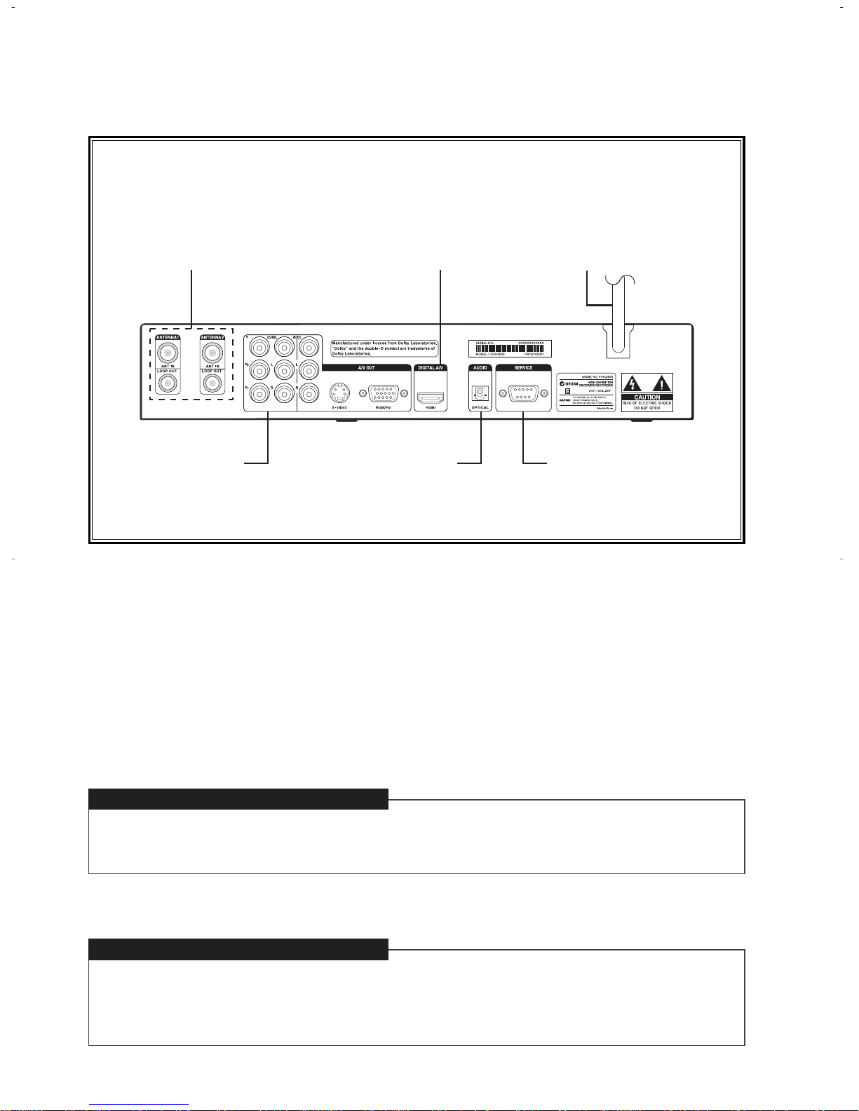
Rear Panel Connectors
-
04 .
Controls
Antenna Input
Power Cord
Note. Connection of input/output connector in rear panel should be done while power is OFF.
Connect the cable fro an off-air TV antenna to Antenna1 input.
Connect Antenna1 loop out to Antenna2 input with RF loop cable.
Rear Side
Service PortA/V Output
Antenna Input Power CordHDMI/DVI Output
Connect to the AC power (AC 240 ~ 250V / 50Hz).
Optical Audio Output
PVR-6990_070710 2007.7.10 12:30 PM 페이지11 MI 2400-175-cmyk-1

9
04 .
Controls -
Rear Panel Connectors (Cont.)
Service Port
A/V Output
The service port is for aintenance and software upgrade in the future.
The ‘A/V output’ consists of the followings :
Y, Pb, Pr : Co ponent video output (576i, 576p, 720p, 1080i)
RGB/HV : RGB, PC onitor output (576p, 720p, 1080i)
HDMI/DVI : HDMI/DVI output (576p, 720p, 1080i)
Video or S-Video : Co posite video or S-Video output (576i)
L, R : Analog audio output
COAXIAL : Digital audio output (Coaxial)
OPTICAL : Digital audio output (Optical)
PVR-6990_070710 2007.7.10 12:30 PM 페이지12 MI 2400-175-cmyk-1

10
Battery Installation for Remote Control
-
04 .
Controls
1. Unlatch the battery co part ent cover on the back
of re ote control.
2. Insert 2 AA batteries as shown, aking sure the
+ and - ends of each battery line up with the
corresponding arks in the battery
co part ent.
3. Snap the cover back to the re ote control.
Remove the battery cover and install batteries like the diagram below.
PVR-6990_070710 2007.7.10 12:30 PM 페이지13 MI 2400-175-cmyk-1
11
05 .
Installation -
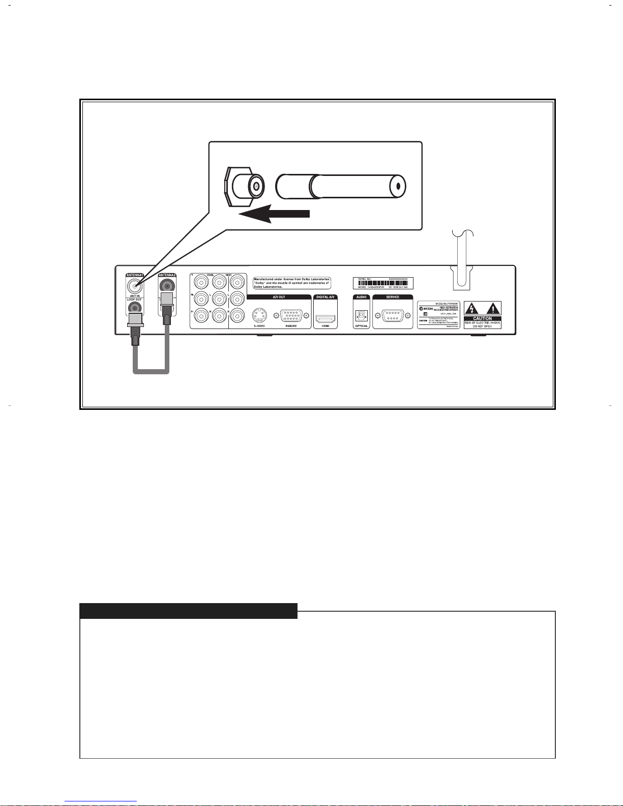
Antenna Input
Connecting Antenna
Connect the antenna or RF cable wire directly to ANTENNA1 IN and connect ANTENNA1 Loop
Out to ANTENNA2 Input by using RF loop cable.
Note
·The STB(Set Top Box) should be unplugged before connecting antenna. (Power OFF mode)
·The RF OUT from the tuner will only work when the unit turns on. It will not give RF OUT during
STANDBY mode.
THE RF LOOP CABLE MUST BE CONNECTED, OTHERWISE THE UNIT WILL NOT BE ABLE
TO TUNE.
PVR-6990_070710 2007.7.10 12:30 PM 페이지14 MI 2400-175-cmyk-1
12
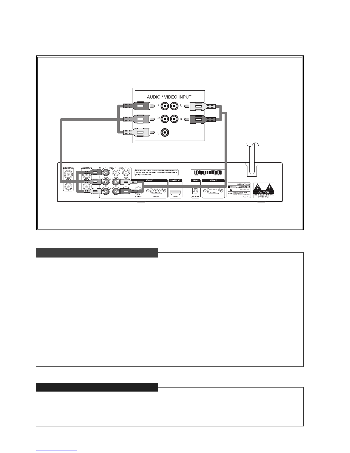
Connection to Digital TV (YPbPr)
-
05 .
Installation
Connect t e Audio Cables
Connect t e Video Cables
Connect an audio cable between the L/R Audio output jacks of the STB and the L/R Audio input jacks
of the digital TV or digital audio a plifier. (Refer to page 18)
Connect a video cable between the Co ponent video output(Y : Green, Pb : Blue, Pr : Red) jacks of
the STB(Set Top Box) and the Co ponent input jacks on the Digital TV according to corresponding
colour. On the Video Out Mode, select YPbPr as Video Output Type and select one of 1080i, 720p,
576p, 576i as Video Output Resolution according to your digital TV.
Note
·By alternately pressing the remote V-OUTPUT buttons (toggling between each button), you will be able to
change the output to‘YPbPr’or‘RGB’. (YPbPr selection is usually used for Component Input, while
RGB selection is used for PC/HDMI Inputs).
·By alternately pressing the remote V-FORMAT buttons (toggling between each button), you will be able to
select one of the formats‘1080i’,‘720p’,‘576p’,‘576i’.
< Digital TV >
PVR-6990_070710 2007.7.10 12:30 PM 페이지15 MI 2400-175-cmyk-1

13
05 .
Installation -
Connection to Digital TV (RGB/HV)
Connect t e Audio Cables
Connect t e Video Cables
Connect an audio cable between the L/R Audio output jacks of the STB and the L/R PC Audio input
jacks of the digital TV or digital audio a plifier. (Refer to page 18)
Connect the RGB/HV output jack of the STB to the RGB input jack of the PC RGB input on the digital
TV. In regard to the Video Out Mode, select RGB as Video Output Type and select one of 1080i,
720p, 576p as Video Resolution according to your digital TV.
Note
·By alternately pressing the remote V-OUTPUT buttons (toggling between each button), you will be able to
change the output to‘YPbPr’or‘RGB’. (YPbPr selection is usually used for Component Input, while
RGB selection is used for PC/HDMI Inputs).
·By alternately pressing the remote V-FORMAT buttons (toggling between each button), you will be able to
select one of the formats‘1080i’,‘720p’,‘576p’,‘576i’.
< Digital TV >
PVR-6990_070710 2007.7.10 12:30 PM 페이지16 MI 2400-175-cmyk-1

14
Connection to RGB PC Monitor
-
05 .
Installation
Connect t e Audio Cables
Connect t e Video Cables
Connect an audio cable between the L/R Audio output jacks of the STB and the external speakers
that contain a sound a p. (Purchase separate jacks for PC speakers.)
Connect RGB/HV video output jack of the STB to the RGB jack of the PC onitor. In regard to
the Video Out Mode, select RGB as Video Output Type and select one of 1080i, 720p, 576p
according to Video Output Resolution of your PC onitor.
Note
·By alternately pressing the remote V-OUTPUT buttons (toggling between each button), you will be able to
change the output to‘YPbPr’or‘RGB’. (YPbPr selection is usually used for Component Input, while
RGB selection is used for PC/HDMI Inputs).
·By alternately pressing the remote V-FORMAT buttons (toggling between each button), you will be able to
select one of the formats‘1080i’,‘720p’,‘576p’,‘576i’.
PVR-6990_070710 2007.7.10 12:30 PM 페이지17 MI 2400-175-cmyk-1

15
05 .
Installation -
Connection to Digital TV (HDMI/DVI)
Connect t e HDMI Cable
Connect the HDMI/DVI output jack of the STB to the HDMI input jack of the digital TV. In regard to
the Video Out Mode, select one of 1080i, 720p, 576p as Video Resolution according to your digital
TV. (Purchase HDMI cable.)
Note
·By alternately pressing the remote V-OUTPUT buttons (toggling between each button), you will be able to
change the output to‘YPbPr’or‘RGB’. (YPbPr selection is usually used for Component Input, while
RGB selection is used for PC/HDMI Inputs).
·By alternately pressing the remote V-FORMAT buttons (toggling between each button), you will be able to
select one of the formats‘1080i’,‘720p’,‘576p’,‘576i’.
·When you connect using HDMI, depending on your digital TV, you can change the value of video
timing by going to the HDMI VIDEO selection at the MENU. The two selections available are :
–HDMI means the value of video timing is setup for HDMI
–YPbPr/RGB means the value of video timing is setup for YPbPr/RGB
·You can view the difference between the two selections above by pressing ‘MARK’. If you see
OUTPUT, and there is a letter ‘H’ in the beginning (eg: OUTPUT: H1080), it means HDMI is selected.
If you see OUTPUT, (eg: OUTPUT: 1080), it means normal YPbPr/RGB is selected.
< Digital TV >
PVR-6990_070710 2007.7.10 12:30 PM 페이지18 MI 2400-175-cmyk-1

16
Connection to HDMI/DVI PC Monitor
-
05 .
Installation
Connect t e Audio Cables
Connect t e Video Cables
Connect an audio cable between the L/R AUDIO output jacks of the STB and the external speakers
that contain a sound a p. (Purchase separate jacks for PC speakers.)
Connect HDMI/DVI jack of the STB to the HDMI/DVI jack of the PC onitor. In regard to the Video
Out Mode, select one of 1080i, 720p, 576p according to Video Output Resolution of your onitor.
(Purchase HDMI-to-DVI adapter.)
Note
·By alternately pressing the remote V-OUTPUT buttons (toggling between each button), you will be able to
change the output to‘YPbPr’or‘RGB’. (YPbPr selection is usually used for Component Input, while
RGB selection is used for PC/HDMI Inputs).
·By alternately pressing the remote V-FORMAT buttons (toggling between each button), you will be able to
select one of the formats‘1080i’,‘720p’,‘576p’,‘576i’.
PVR-6990_070710 2007.7.10 12:30 PM 페이지19 MI 2400-175-cmyk-1

17
05 .
Installation -
Connection to Analog TV (Composite/S-Video)
Connect t e Audio Cables
Connect t e Video Cables
Connect an audio cable between the L/R Audio output jacks of the STB and the L/R Audio input jacks
of the analog TV.
Connect a co posite cable between the Video output jack of the STB and the Video input jack of the
analog TV. Or, connect an S-Video cable between the S-Video output jack of the STB and the S-
Video input jack of the analog TV. You can connect either co posite Video or S-Video cable. When
connecting using Co posite Video or S-Video, please ensure to select 576i of the set top box, by
pressing V.FORMAT button on the re ote.
Note
·By alternately pressing the remote V-OUTPUT buttons (toggling between each button), you will be able to
change the output to‘YPbPr’or‘RGB’. (YPbPr selection is usually used for Component Input, while
RGB selection is used for PC/HDMI Inputs).
·By alternately pressing the remote V-FORMAT buttons (toggling between each button), you will be able to
select one of the formats‘1080i’,‘720p’,‘576p’,‘576i’.
< Analog TV >
If you use Composite/S-VIDEO connection, you must select 576i format. Otherwise all of the
OSD (On Screen Display) will not function, including MENU, MARK, etc.
PVR-6990_070710 2007.7.10 12:30 PM 페이지20 MI 2400-175-cmyk-1

18
Connection to Digital Audio Amplifier
-
05 .
Installation
Connect t e Digital Audio Output
Connect audio cables fro the OPTICAL or COAXIAL digital audio output jacks of the STB to the
OPTICAL or COAXIAL digital audio input jacks of the digital audio decoder or the a plifier. Do not
connect the coaxial and optical audio output si ultaneously and be sure to connect either optical or
coaxial cable to avoid any da age to digital audio decoder or a plifier that ay occur. It is
reco ended to use OPTICAL connection if a digital audio decoder or a plifier provides both
OPTICAL and COAXIAL input jacks.
Note
·When you connect using HDMI cable, the digital audio in the TV is detected. So if it detects PCM,
then the Digital OUT will be at PCM too. If it detects Dolby Digital, then the Digital OUT will be at
Dolby Digital too.
·There are 3 options on HDMI AUDIO in the menu.
ⅰAUTO : If the broadcaster is broadcasting PCM/MPEG, the Digital OUT will be PCM. If the
broadcaster is broadcasting Dolby Digital, the Digital OUT will be Dolby Digital.
ⅱPCM : Whatever the broadcaster is broadcasting (PCM/MPEG or Dolby Digital), the Digital OUT
will be at PCM.
ⅲDISABLE: Select this, in order to have Digital Audio OUT in Dolby Digital for using external amplifier
at below conditions.
–The TV digital audio support only PCM, and HDMI cable is used.
–The broadcaster is broadcasting Dolby Digital.
< Audio Amplifier >
PVR-6990_070710 2007.7.10 12:30 PM 페이지21 MI 2400-175-cmyk-1
Table of contents
Other NextWave Digital Receiver manuals


