NFHS Network PIXELLOT S2S DOUBLE PLAY User manual

An overview of equipment and tools required for basic installations
PIXELLOT S2S DOUBLE PLAY
INSTALL GUIDE

TABLE OF CONTENTS
2
S2S DOUBLE PLAY OVERVIEW . . . . . . . . . . . . . . . . . . . . . . . . . . . . . . . . . PAGE 3
S2S DOUBLE PLAY DIAGRAM . . . . . . . . . . . . . . . . . . . . . . . . . . . . . . . . . PAGE 4
S2S CAMERA PLACEMENT . . . . . . . . . . . . . . . . . . . . . . . . . . . . . . . . . . . . PAGE 5
VPU PLACEMENT . . . . . . . . . . . . . . . . . . . . . . . . . . . . . . . . . . . . . . . . . . . PAGE 6
MOUNTING THE S2S CAMERA . . . . . . . . . . . . . . . . . . . . . . . . . . . . . . . . PAGE 7
CONNECTING THE S2S CAMERA . . . . . . . . . . . . . . . . . . . . . . . . . . . . . . . PAGE 8
ALTERNATE ANGLE CAMERA PLACEMENT . . . . . . . . . . . . . . . . . . . . . . . PAGE 10
MOUNTING THE ALTERNATE ANGLE CAMERA . . . . . . . . . . . . . . . . . . . PAGE 11
CONNECTING THE ALTERNATE ANGLE CAMERA . . . . . . . . . . . . . . . . . . PAGE 15
ADDITIONAL GUIDES . . . . . . . . . . . . . . . . . . . . . . . . . . . . . . . . . . . . . . . . PAGE 16
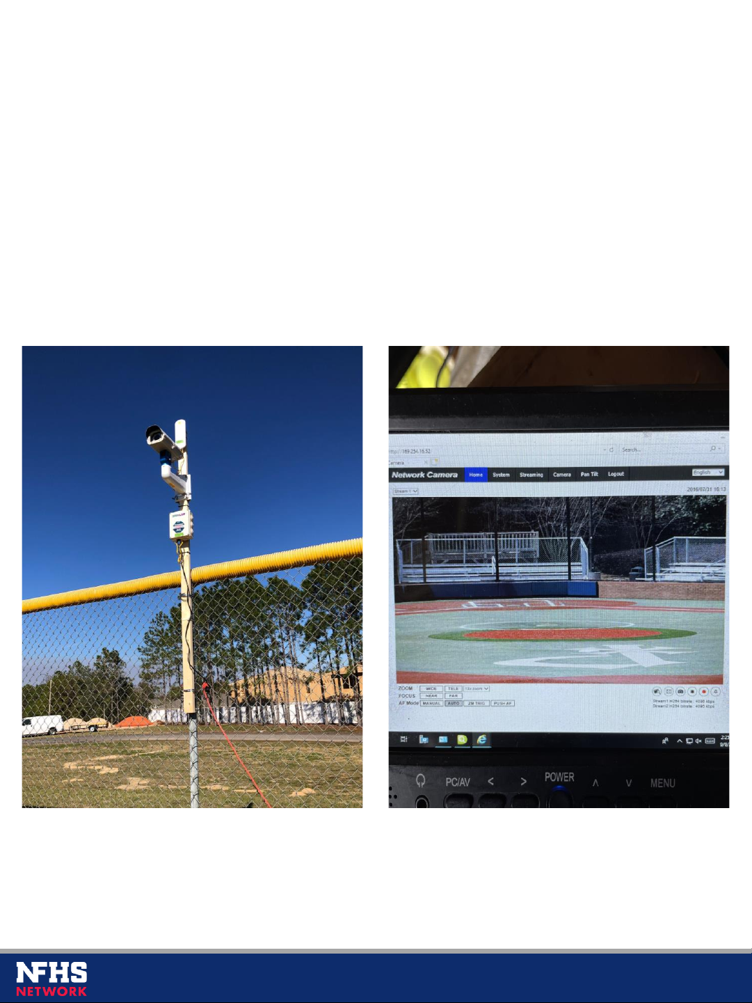
S2S DOUBLE PLAY OVERVIEW
3
The S2S Double Play system is used for baseball and softball fields and consists
of the following:
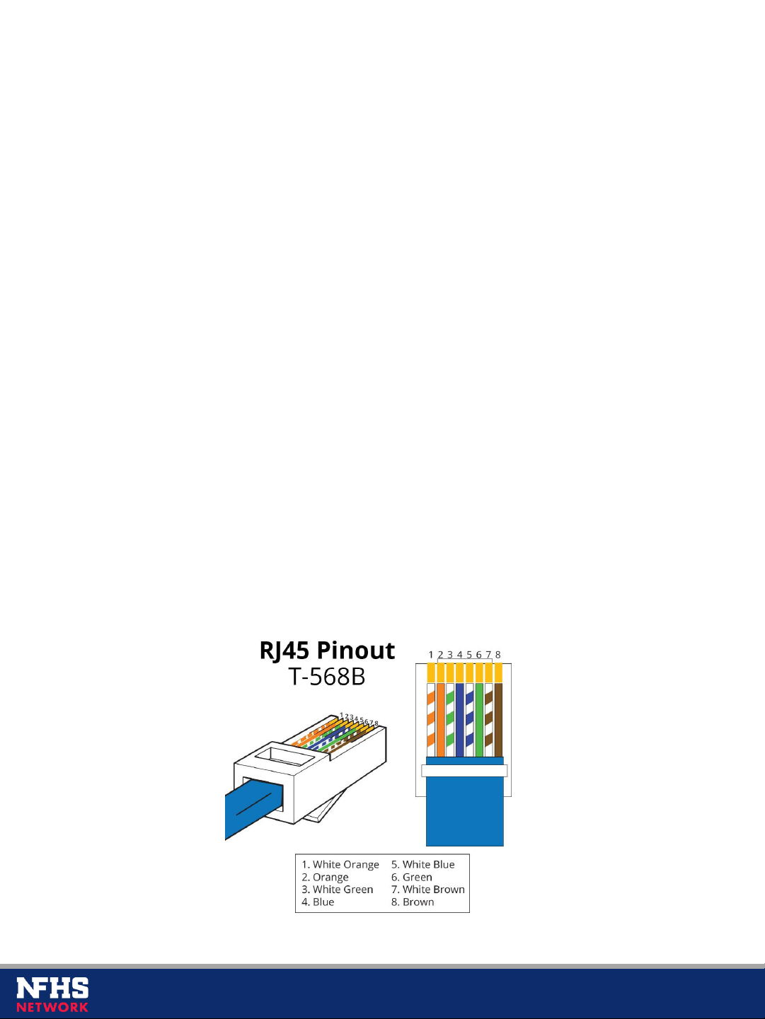
•1x Pixellot S2S camera, which connects to, and is powered by, the VPU
via 1x Cat6 ethernet cable*
•1x Pixellot computer (VPU) requiring hardline internet access and power
•1x Alternate Angle camera, which connects to, and is powered by, the
provided PoE switch via 1x Cat6 ethernet cable
•1x 5-port PoE switch requiring power
•2x Ubiquiti point-to-point dishes, one of which connects to, and is
powered by, the PoE switch via 1x Cat6 ethernet cable, and the other of
which connects to, and is powered by, the VPU via 1x Cat6 ethernet cable
•1x Scorelink device, which connects to, and is powered by, the VPU via 1x
USB cable
*When terminating the Cat6 cables, please use pinout B as shown below:

S2S DOUBLE PLAY DIAGRAM
4
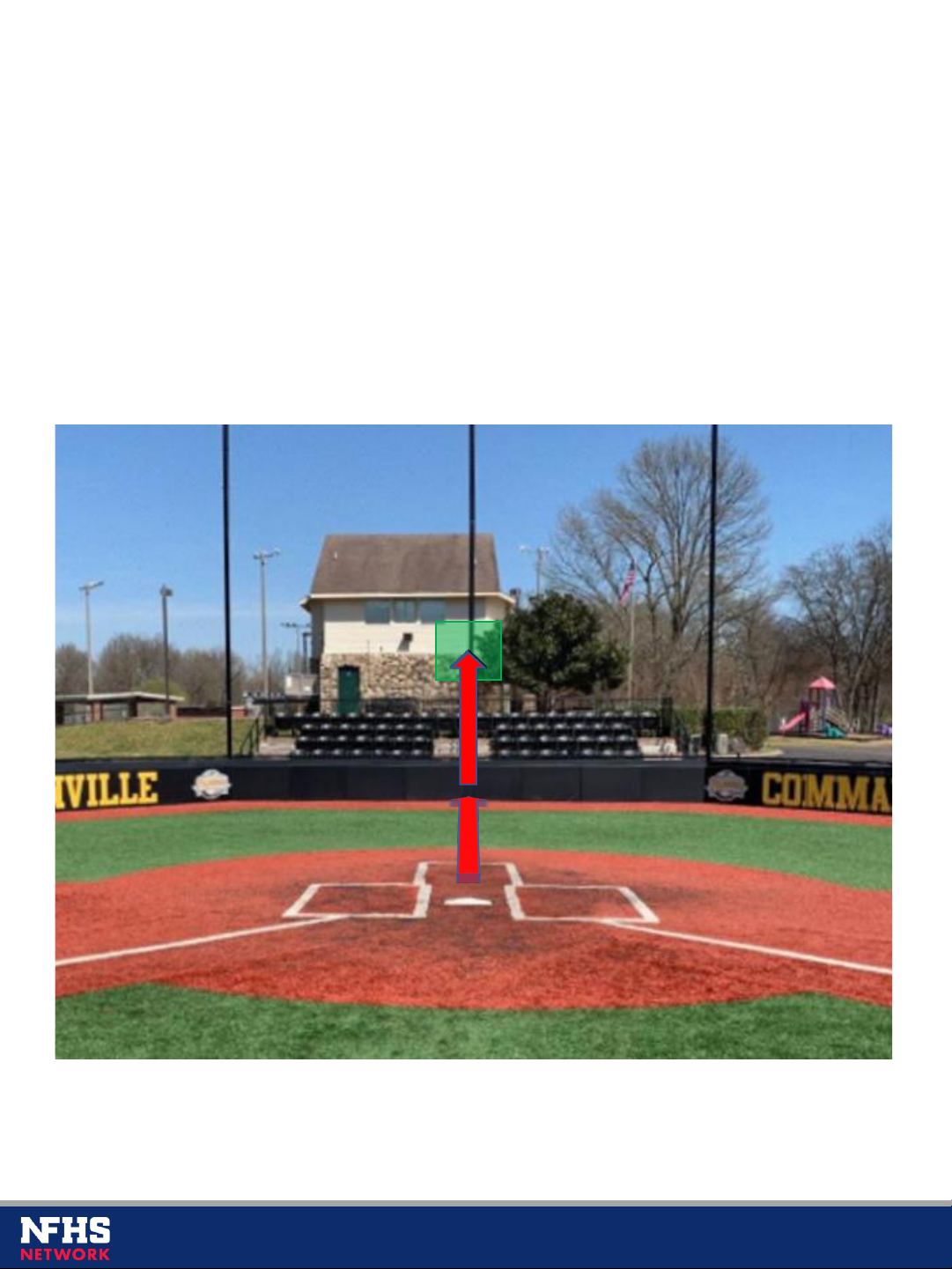
The S2S camera will be mounted behind home plate, preferably in front of the
backstop fence rather than behind it. We recommend a 1:1 standoff (distance
from home plate) to height ratio or as close to it as possible, with a minimum
standoff of 10’. Below is a photo of a typical baseball field and the
recommended mounting area:
S2S CAMERA PLACEMENT
5
VPU PLACEMENT
6
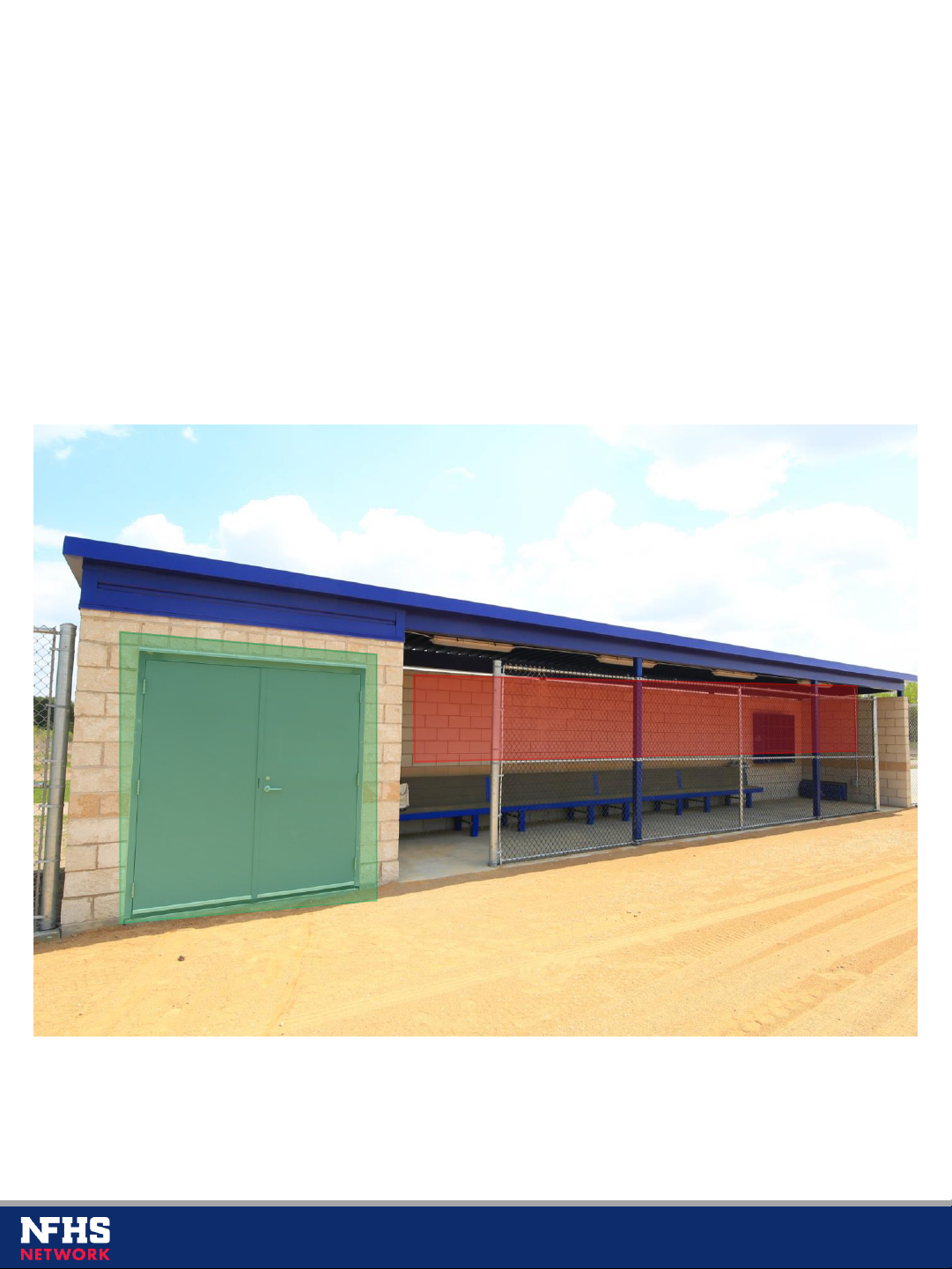
The VPU and its cabinet must be mounted within 200’ of the S2S camera and in
a secure and weatherproof location with power and hardline internet access (if
there is no internet access, a separate point-to-point must be used). If no
weatherproof location is available, please let us know as we may need to supply
a weatherproof cabinet.
NOT WEATHERPROOF
WEATHERPROOF

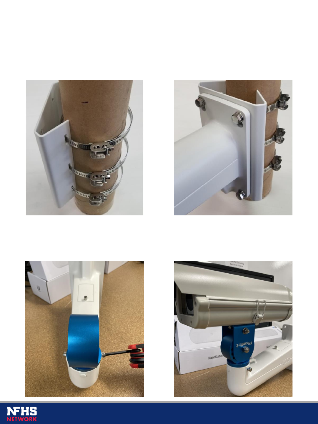
MOUNTING THE S2S CAMERA
7
If mounting the S2S camera to a flat surface such as a wall, use the four
holes on the base plate to secure it.
If mounting the S2S camera to a pole, use the included steel clamps. Thread
them through the back of the base plate and secure them around the pole.

CONNECTING THE S2S CAMERA
8
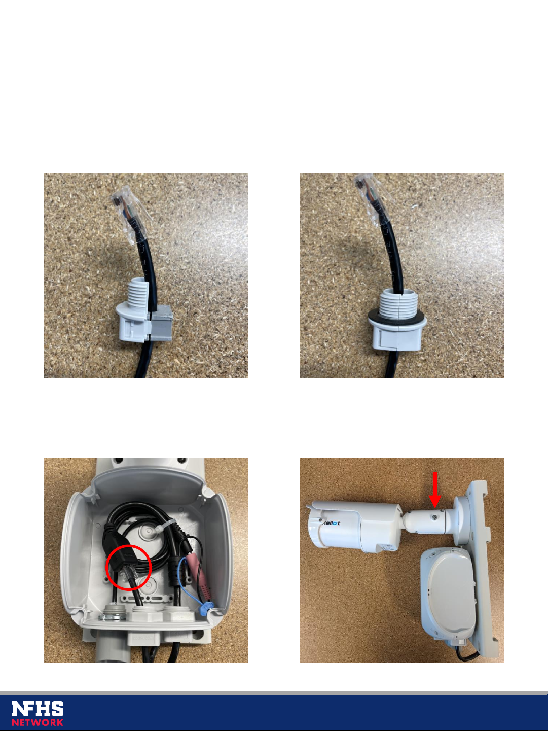
To connect the S2S camera, you must first open its junction box by turning the
four screws. Then, detach the waterproof connector by unscrewing the plastic
hex nut.
Next, split the waterproof connector apart by lifting the teeth from both sides.
CONNECTING THE S2S CAMERA CONT.
9
Push the Cat6 cable (the jacket portion of the cable, not the RJ45 connector)
into the opening of the split grommet. Then, snap the other side of the
waterproof connector back onto it and place the rubber seal on top.
Reattach the waterproof connector to the junction box and connect the Cat6
cable. This Cat6 cable will run directly into one of the four ports on the back of
the VPU. Finally, adjust the S2S angle using the single screw on the side.
ALTERNATE ANGLE CAMERA PLACEMENT
10
The alternate angle camera will be installed near the back center of the outfield,
pointing at home plate over the pitcher’s mound. It should be installed slightly
off center so that the pitcher won’t block the view of the batter at home plate. It
can be mounted directly on the outfield fencing or on a pole/wall in the outfield
and must be at least 10’ high.

MOUNTING THE ALTERNATE ANGLE CAMERA
11
First, open the latch on the weatherproof housing and unscrew the two mounting
plate screws. Set these and the additional screws aside for later. Then, unscrew
the fan from the housing. This can be disposed of as it’s not needed.
Screw the base onto the alternate angle (AA) camera. Then, reinstall the two
mounting plate screws about 1-1/4” from the front of the plastic rail. Do NOT
tighten these all the way down, as the mounting plate will slide under them.

Place the mounting plate onto the small screws and slide it forward to ensure it
fits snugly under the screws (loosen/tighten the screws as needed).
Remove the plate again and, using the included screw, attach the mounting
plate to the AA camera base plate. Make sure the small screw holes on the back
of the mounting plate clear the back of the AA camera.
MOUNTING THE AA CAMERA CONT.
12

Place the AA camera and mounting plate onto the previously installed screws
and slide it forward to lock it in place. Then, install the other two included screws
on the back of the mounting plate. Next, disassemble the angle bracket.
Before proceeding, ensure the center bolt on the angle bracket is tightened
down and the cutout portion is facing one of the sides (not straight ahead).
Then, place the outer shell of the angle bracket onto the bottom of the housing
and secure it using the included screws and split lock + flat washers.
MOUNTING THE AA CAMERA CONT.
13
If mounting to a pole or fence, use the included mounting plate and steel clamps. Thread
the clamps through the back of the plate and secure them around the pole. Then, use
the included screws to secure the arm to the plate. If mounting to a wall, secure the arm
directly to the wall. The opening at the end of the arm should face upwards.
Insert the angle bracket into the arm and tighten the two hex screws on either side of it.
Finally, place the housing onto the arm and secure it using the two bolts. Do not tighten
them all the way as you will need to carefully aim the camera until home plate is
centered in view. Once the angle is set, fully tighten them down.
MOUNTING THE AA CAMERA CONT.
14

To transmit the AA camera’s signal to the VPU, you will need to use the Ubiquiti dishes and
5-port PoE switch. First, connect one Cat6 cable from the AA camera directly into the 5-
port PoE switch (do not plug into port 5 on the switch). As a reminder, the PoE switch
needs power and a weatherproof location.
Next, install the dish labeled FIELD in the outfield; this can often be installed next to the AA
camera. Connect one Cat6 cable from the “Main” port of the dish directly into the 5-port
PoE switch (do not plug into port 5 on the switch, and do not use the Ubiquiti PoE
injector). Finally, install the dish labeled VPU at the VPU location, pointing toward the
outfield dish. Connect one Cat6 cable from the “Main” port of the dish directly into one of
the four ports on the VPU.
CONNECTING THE AA CAMERA
15

Table of contents
Popular Digital Camera manuals by other brands


Basler Vision Technologies
Basler Vision Technologies Basler scout scA640-70gm user manual

Sony
Sony Cyber-shot DSC-W710 instruction manual

GE
GE Power PRO series G100 quick start guide
 user guide")
Canon
Canon PowerShot SD110 (PC1085) user guide

VADDIO
VADDIO IntelliSHOT installation guide

Arenti
Arenti OUTDOOR1 quick guide