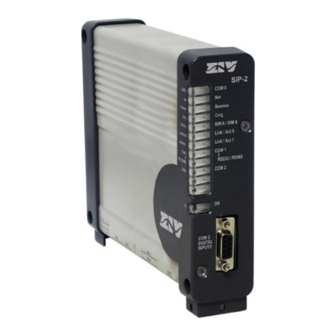
Niobrara MEB II Assembly instructions

MEB II Manual
MEB II
Installation and Programming Manual
This manual covers the MEB II Modbus Plus to Ethernet Bridge.
Effective: January 10 2013
Niobrara Research & Development Corporation
P.O. Box 3418 Joplin MO 64803 USA
Telephone: (800) 235-6723 or (417) 624-8918
Facsimile: (417) 624-8920
http://www.niobrara.com

Modicon Square D SY/MAX Compact Quantum M340 Momentum Premium are
trademarks of Schneider-Electric.
Subject to change without notice.
© Niobrara Research & Development Corporation 2013. All Rights Reserved.

Contents
1 Introduction.................................................................................................9
2 Installation.................................................................................................11
Device Mounting/Removal...................................................................11
Power Supply........................................................................................12
Ethernet.................................................................................................13
Setting the IP Address.......................................................................13
Setting the Subnet Mask...................................................................14
Setting the Default Gate...................................................................14
Ethernet Connection.........................................................................14
Modbus Plus..........................................................................................17
Modbus Plus Configuration..............................................................17
Modbus Plus Connection..................................................................18
Modbus Plus Lights..........................................................................20
Serial Ports............................................................................................21
RS-232 Ports.....................................................................................21
RS-485 Ports.....................................................................................23
Software Installation.............................................................................25
Updating the MEBII Firmware.............................................................26
Updating Firmware through the Web server....................................26
Updating Firmware using RPCLOAD.............................................27
3 Modbus/TCP Operation.............................................................................29
Server Operation...................................................................................29
Default Modbus Routing Table........................................................31
AutoFix Modbus Table.....................................................................32
Front Panel Modbus Route Edit.......................................................33
Client Operation....................................................................................34
AutoFill TCP Table...........................................................................37
Front Panel Edit of TCP Table..........................................................38
4 Modbus Serial Operation..........................................................................39
Slave Operation (External Master)........................................................39
Default Modbus Routing Tables.......................................................41
AutoFix Modbus Table.....................................................................42
Master Operation (External Slave)........................................................42
AutoFill TCP Table...........................................................................45
5 Legacy SY/MAX Operation......................................................................47
Translations...........................................................................................47
iii

Modbus to SY/MAX Translations....................................................47
SY/MAX to Modbus Translations....................................................48
Error Translations.............................................................................48
SY/MAX Serial.....................................................................................49
NET-TO-NET Mode.........................................................................51
SY/MAX Ethernet.................................................................................54
SY/MAX Routing.............................................................................54
PowerLogic Serial Modes.....................................................................58
6 Hot MB+ Operation..................................................................................60
Automatic Redundant Operation...........................................................60
Requirements and Restrictions.........................................................60
“Primary” Unit Configuration Procedure.........................................61
“Secondary” Unit Configuration Procedure.....................................62
Example............................................................................................63
Reasons for Automatic Switchover.......................................................64
Hot MB+ Statistics and Information Registers.....................................64
Serial Number...................................................................................66
MB+ Global Data.............................................................................66
Controlled Switchover......................................................................66
7 Front Panel Operation...............................................................................67
Keypad Buttons.....................................................................................67
LCD Screen...........................................................................................67
Backlight...........................................................................................67
Operating Screens.................................................................................67
Splash Screen....................................................................................67
Main Menu Screen...........................................................................68
Configuration Menu..............................................................................68
Comms Menu Screen.......................................................................69
Ethernet Configuration Menu...........................................................69
IP Addr Screen..................................................................................70
Subnet Mask Screen.........................................................................70
Default Gate Screen.........................................................................71
IP Source Screen...............................................................................71
Ethernet Protocol Screen..................................................................72
Ethernet Drop Screen......................................................................72
Modbus Route Screen.......................................................................73
IP Route Screen................................................................................74
Ethernet Mode Screen......................................................................75
Serial Port Menu...............................................................................76
Port 1 Menu......................................................................................76
Modbus Plus Edit Screen..................................................................77
Display Edit Screen..........................................................................78
Status Menu Screens.............................................................................78
Stats Screen......................................................................................78
iv Contents

Enet Status Screen............................................................................79
MB+ Status Screen...........................................................................79
App Menu.............................................................................................80
Switch Screen...................................................................................80
Info Menu..............................................................................................81
MAC Address Screen.......................................................................81
Serial Number Screen.......................................................................82
Versions Screen................................................................................82
MB+ Drops Screen...........................................................................82
Enet Drops Screen............................................................................83
System Menu.........................................................................................84
Reboot Screen...................................................................................84
Factory Defaults Screen...................................................................84
Password Screen...............................................................................85
8 Recommended Cables...............................................................................87
RS-232 Cables.......................................................................................87
MM1 (PC to MEBII)........................................................................87
MM2 (Modicon PLC to MEBII)......................................................87
MM3 (MEBII to emulate a 9-pin PC port).......................................88
RS-485 Cables.......................................................................................89
MU7 (MEBII to SY/MAX)..............................................................89
MEBII Master to 4-wire RS-485 Slaves..........................................89
MEBII to 2-wire RS-485..................................................................90
9 Web Server................................................................................................93
Login.....................................................................................................93
Home ....................................................................................................95
Configuration........................................................................................95
Ethernet.............................................................................................95
IP Settings.........................................................................................96
Ethernet Port Parameters..................................................................97
Modbus Routing for Ethernet Port...................................................98
TCP Routing Table...........................................................................99
I/O Scanner.....................................................................................100
Serial Ports..........................................................................................101
Port Parameters...............................................................................101
Serial Port Modbus Routing Table.................................................102
Serial Port Auto Scan......................................................................103
Modbus Plus Port Parameters.........................................................104
Modbus Plus Global Data...............................................................105
Statistics..............................................................................................107
Ethernet Router Stats......................................................................107
SY/MAX 802.3 Ethernet Nodes.....................................................108
Serial Port ......................................................................................109
Port 2 Hot Modbus Statistics..........................................................110
Contents v

Modbus Plus Router........................................................................111
MB+ Chipset...................................................................................112
Modbus Plus Nodes........................................................................113
Module Info....................................................................................116
Config Overview............................................................................117
Register Viewer...............................................................................118
Admin Menu.......................................................................................119
Change Passwords..........................................................................119
Configuration Backup....................................................................120
Configuration Restore....................................................................121
Hot Modbus Plus............................................................................122
Firmware Update............................................................................123
Reset to Factory Defaults...............................................................124
10 MEBSW32............................................................................................125
Startup Screen.....................................................................................125
Main Menu..........................................................................................127
oNline Menu.......................................................................................128
Edit port parameters.......................................................................129
Edit Modbus routing.......................................................................130
Auto Scan Edit................................................................................130
Global Data.....................................................................................131
TCP Routing...................................................................................132
offline Menu........................................................................................133
Read from disk to memory.............................................................134
Write from memory to disk............................................................134
Edit configuration in memory........................................................134
edit Modbus Routing......................................................................135
edit Global data table......................................................................135
edit TCP routing table.....................................................................135
Send memory to module.................................................................135
Fetch memory from module...........................................................135
Print configuration in memory.......................................................135
Delete configuration file.................................................................135
Copy offline to module flash..........................................................135
Quit offline functions......................................................................136
Utility Menu........................................................................................136
View registers.................................................................................136
view module Revision....................................................................137
view Statistics.................................................................................138
Terminal emulator...........................................................................139
CTS monitor...................................................................................139
Modbus+ station list.......................................................................140
Ethernet node list............................................................................140
downLoad firmware to module......................................................141
vi Contents

Write setup to EEPROM................................................................141
Setup Menu.........................................................................................142
Serial communication.....................................................................142
Terminal emulator...........................................................................144
Register viewer...............................................................................144
Quit Menu...........................................................................................145
Contents vii

1 Introduction
The Niobrara MEBII is a stand-alone DIN rail mount Modbus Plus to Ethernet Bridge. It
features a redundant cable Modbus Plus (MB+) port at leaset one 10/100BaseTX
Ethernet port and two isolated serial ports. The MEBII allows simultaneous pass-through
routing data messages from Modbus/TCP Ethernet MB+ and Modbus serial between all
ports. Full support of PLC programming message pass-through is also provided on all
communication ports including Unity Pro Concept ProWORX and Modsoft.
MEB II Manual 9
Figure 1.1:MEBII Front Panel
Keypad
Dual Cable
Modbus Plus
100BaseTX
Ethernet
24VDC
Power
Port 1
(RS-232)
LCD showing
IP Address
MB+ Node
Port 2
(RS-232)
Port 1
(RS-485) Port 2
(RS-485)

The MEBII features at least one 100BaseTX Ethernet port that supports Modbus/TCP as
both a client and a server at the same time. The MEBII can support up to 64
simultaneous Modbus/TCP connections. A routing table is used to map the incoming
Modbus/TCP Destination Index (Slave Address) from a client to a downstream route that
determines where the message is directed. This route may point to a PLC on MB+ a
slave on one of the MEB's serial ports or even back out the Ethernet port to a different
device. The Ethernet port also supports the older SY/MAX 802.3 protocol for smoothly
integrating legacy Square D Model 650 and 450 PLCs into a Modbus/TCP system.
The MEBII+201 model includes two 100BaseTX Ethernet ports that support Rapid
Spanning Tree Protocol (RSTP) allowing the MEBII to be used in a copper ring network
for redundant Ethernet cable connections. It may also be used in a daisy-chain Ethernet
network as well.
The Modbus Plus port supports dual-cable redundant MB+ networking but may simply
be used in a single-cable system by leaving one of the ports open. The standard 5-drop
MB+ routing structure is supported allowing full access to MB+ devices on the local
network or through Modicon Bridge Plus and Bridge Mux devices.
There are two isolated serial ports on the MEBII. Each port may be selected to use its
RJ-45 connector for RS-232 or a removable 5-pin screw connector for RS-485. The RS-
485 port may operate in 4-wire RS-422 4-wire RS-485 or 2-wire RS-485 modes with
selectable termination and bias. The two serial ports may be independently configured
for one of 18 different protocols including Modbus RTU Modbus ASCII and SY/MAX.
The default mode supports Modbus RTU and can dynamically switch between being a
master or a slave.
The MEBII features a front panel backlit LCD and keypad that may be used for
configuration and troubleshooting. The IP Address MB+ node address and most serial
port settings may be configured through this interface which may be password protected
to prevent unauthorized changes.
A built-in web server is included in the MEBII. This password protected AJAX
Javascript enabled server allows two user levels for configuration backup/restore
troubleshooting and even firmware updating – all from a standard browser.
The MEBII also includes a “Hot MB+” mode that allows two MEBII units to work
together to provide an automatic fully redundant primary/standby system for high
availability systems.
10 Introduction 1 MEB II Manual

2 Installation
WARNING: Do not connect the MEB II to any Ethernet or MB+ network before
configuring the appropriate network addresses. Duplicate network address may
lead to improper network communication equipment damage injury or death.
Device Mounting/Removal
(1) Hook the top notch on the upper lip of the DIN rail.
(2) Rotate the MEBII until the lower latches click tight.
(3) Use a screw driver to unclip the lower latches to remove the MEBII from the DIN
rail.(See Figure 2.1 DIN Rail Mounting and Removal)
MEB II Manual 11
Figure 2.1 DIN Rail Mounting and Removal
3
DIN Rail
(TS-35)
DIN Rail
(TS-35)
Click
2

Power Supply
Connect a suitable 24VDC power to the three position removable connector. The
MEB II requires a 5W minimum supply and will operate on 9-30Vdc but 24Vdc is
recommended. (See Figure 2.2 Power Supply Diagram) An external fuse is
recommended. Typical power supply wire colors are:
•Red = 24Vdc (+)
•Black = 24Vdc (-)
•Green = Earth Ground
12 Installation 2 MEB II Manual
Figure 2.2 Power Supply Diagram
DIN Rail
(TS-35)
Fuse
Disconnect
24Vdc Power Supply

Ethernet
Setting the IP Address
The MEBII defaults to a fixed IP Address of 10.10.10.10. This is easy to change through
the use of the front panel keypad. The MEBII supports fixed IP Address DHCP or
BOOTP. Press the key four times to step through the “> Main > Config > Comms >
Ethernet >” pages.
If BOOTP or DHCP is desired arrow to the IP Source menu item and then press the
key. The and arrows are used to select FIXED DHCP or BOOTP. The key is
used to accept the new value and return to the previous menu.
NOTE: BOOTP and DHCP operation usually requires that the server be configured for
the MAC Address of the MEBII. The MEBII's MAC address is printed on the serial
number label and is also shown on IP Source screen. The example below shows a MAC
Address of 00:20:BD:0C:35:01.
If a fixed address is required make sure that the IP Source is set to Fixed then select the
Address page. The and arrows are used to adjust the values while the and
arrows move between fields. The key is used to accept the new value.
MEB II Manual 2 Installation 13
Figure 2. : IP Address Source Screen
Figure 2.4: Fixed IP Address Screen

The “Autofill IP Tables?” offers the automatic filling of the TCP client table. Each of the
200 entries in the TCP table will be set to the first three octets of the MEBII's IP Address
and the last octet will be set to the index number 0-199.
Setting the Subnet Mask
The Subnet Mask edit page is designed to quickly step through the valid bit-mapped
options. Pressing the and arrows adjusts the mask value. The key is used to
accept the new value.
The “Auto Set Default Gate?” applies the new subnet mask to the current IP Address to
preset the Default Gate.
Setting the Default Gate
The Default Gate edit page functions just like the IP Address edit page.
Ethernet Connection
After the IP Address is configured for the MEBII it is safe to connect the Ethernet port to
the network. The MEBII includes a standard RJ-45 Ethernet connector with indicators
for Link/Activity (green LED) and 100Mb (amber LED). (See Figure 2.7 Ethernet Port)
The green Link/Activity light illuminates when the MEBII has a valid link to the attached
14 Installation 2 MEB II Manual
Figure 2.5: Subnet Mask Screens
Figure 2.6: Default Gate Screen

network port and blinks off while experiencing network traffic. The 100Mb amber LED
is illuminated when the Ethernet port has negotiated 100Mb operation and off while
configured for 10Mb operation.
The MEBII's Ethernet port supports 10/100BaseTX auto-crossover operation. Standard
CAT5 cables may be used to connect the MEBII to Ethernet switches and hubs.
MEB II Manual 2 Installation 15
Figure 2.7 Ethernet Port
Pin 1 100MB
LED
Link/
Activity
LED

The status of the Ethernet port may be inspected through the front panel LCD by
choosing “> Main > Status > Enet >”
The Ethernet port defaults to “Auto” mode but may be manually set to a fixed 10BaseT
or 100BasetT with fixed Full or Half Duplex operation.
16 Installation 2 MEB II Manual
Figure 2.8 Typical Ethernet Connection
Quantum
NOE
Ethernet
Switch
Cat5
Cables
PC with
Ethernet
Figure 2.9: Ethernet Port Status

Modbus Plus
Modbus Plus Configuration
The Modbus Plus (MB+) node of the MEBII may be assigned an address between 1 and
64 with a default value of 1. This address must be unique within the local MB+ network
segment. To edit the MB+ drop number choose:
“> Main > Config > Comms > Modbus+ >“
The and arrows are used to adjust the new MB+ drop. The key is used to accept
the new value.
NOTE: If the MEBII is physically connected to the local MB+ network it will
automatically skip MB+ drop numbers that are already in use. The drop numbers of the
Ethernet and serial ports will also be skipped if they fall within the valid MB+ range.
After selecting the new MB+ drop number the screen will change to ask if the user
would like to AutoFix the Routing Tables. Choosing Yes will result in the Modbus
Routing Tables for the Ethernet and serial ports 1and 2 being updated to include the new
drop number of the MB+ port. If No is selected these tables will not be updated and
many of the routes will not longer work properly – they must then be edited manually.
MEB II Manual 2 Installation 17
Figure 2.11: Edit Modbus Plus Drop
Figure 2.10: Ethernet Mode Screen

Modbus Plus Connection
NOTE: See the Modicon Modbus Plus Network Planning and Installation Guide
890 USE 100 00 for complete instructions on proper MB+ cable installation
methods and considerations.
Modbus Plus has very specific rules about minimum and maximum cable lengths
number of nodes per segment the use of repeaters and cable termination. It is
extremely important to follow the rules spelled out in the above mentioned guide
for proper network operation.
The MEBII includes two MB+ DB9 connectors labeled “A” and “B”. (See Figure 2.12
Modbus Plus Pinout) These ports may be used in a “dual-cable” Modbus Plus network.
This does not mean that the MEBII has two MB+ nodes it behaves as a single MB+ node
with two physical network connectors. The dual-cable system uses redundant wiring
between nodes for added network integrity. (See Figure 2.13 Typical Dual-Cable MB+
Connection)
18 Installation 2 MEB II Manual
Figure 2.12 Modbus Plus Pinout
Data B
Pin 3
Data A
Pin 2
Shield
Pin 1

The MEBII may be used in a “single-cable” network by simply connecting the MB+
network to port “A”. (See Figure 2.14 Typical Single-Cable MB+ Connection)
MEB II Manual 2 Installation 19
Figure 2.1 Typical Dual-Cable MB+ Connection
Terminator on
End node Terminator on
End node
Terminator on
End node
Terminator on
End node
Cable B
Cable A

Modbus Plus Lights
The MEBII includes one green LED and two red error LEDs to provide visual status of
the MB+ network operation.
If the red error A or error B lights blink momentarily it indicates that a message error was
detected on the corresponding network port. A steady ON error light indicates that a hard
fault exists. The fault may either be in the cable or on a node connected to that cable. If
communication on one cable is lost the other should continue normally.
The green Active light flashes in patterns to indicate the operating state of the MB+ node.
(See Table 2.1: MB+ Green Active Flashes)
20 Installation 2 MEB II Manual
Figure 2.14 Typical Single-Cable MB+ Connection
Terminator on
End node
Terminator on
End node
Single-Cable
Port B
Not Used

Table 2.1: MB+ Green Active Flashes
Green Active Flashes Meaning
Six steady flashes per second Normal Operating State
One flash per second Offline monitoring network traffic
Two flashes then OFF for two seconds Hears traffic but never receives the Token
Three flashes then OFF for 1.7 seconds Sole Station no other nodes detected
Four flashes then OFF for 1.4 seconds Offline Duplicate Node Address Detected
Serial Ports
The MEBII includes two isolated serial ports. Separate connectors are provided for each
port with an RJ-45 connector for RS-232 and a removable 5-position screw terminal
connector for RS-485/422.
NOTE: Port 1 is electrically isolated from Port 2. The RS-232 connector of a given port
is not isolated from the RS-485 connector of the same port.
S-232 Ports
The RJ-45 connectors are used for RS-232 operation. The pin configuration is shown in
Table 2.2: RJ45 RS-232 Pinout. The Niobrara MM1 cable is used to connect an one of
these ports to the a standard 9-pin serial port on a PC. (See Figure 8.1.: MM1 Serial
Cable)
MEB II Manual 2 Installation 21
Figure 2.16 RS-2 2 Port 1 Figure 2.15 RS-2 2 Port 2
Pin 1
RX
LED
TX
LED
Pin
TX
LED
RX
LED
Table of contents

