Njoy Ascet 5K-60/1P2T2 User manual

English
Română
Ascet 5k-6k Installaon Manual
(Hardware)
Manual de Instalare
(Hardware)
Before using this product, carefully read all product documentaon and retain it for future reference.
SIH12005L032ACCU0B - Ascet 5K-60/1P2T2
SIH12005L052ACCU0B - Ascet 5K-120/1P2T2
SIH12006L032ACCU0B - Ascet 6K-60/1P2T2
SIH12006L062ACCU0B - Ascet 6K-120/1P2T2
320.06.23.0

Content
Forward 1
Symbol Conventions 2
Safety 2
1.1 Symbols Used 3
1.2 Safety Precaution 3
Product Introduction 5
2.1 Overview 5
2.2 Product Appearance 7
2.3 Model Denition 9
Installation 10
3.1 Packing List 10
3.2 Selecting the Mounting Location 12
3.3 Mounting 14
Electrical Connection 15
4.1 Inverter’s setup connection 15
4.2 Grounding 20
4.3 Grid/EPS Connection 21
4.4 Battery Connection 22
4.5 PV Connection (N/A for AC Couple Inverter) 24
4.6 Meter/CT Connection 25
4.7 Communication Connection 27
System Operation 38
5.1 Inverter Working Mode 38
5.2 Startup/Shutdown the System 46
Commissioning 47
6.1 Inspection 47


1
Please read this manual before using the product.
This user manual introduces the inverter in terms of its installaon,
electrical connecons, operaon, commissioning, maintenance,
and troubleshoong. Please read through the manual carefully
before installing and using the inverter, and keep the manual well
for future reference.
Forward
Preface
About This Manual
This manual describes the installaon, connecon, the use of APP,
commissioning and maintenance etc. of ESS inverter. Please rst read
the manual and related documents carefully before using the product
and store it in a place where installaton, operaon and maintenance
personnel can access it at any me. The illustraon in this user manual
is for reference only. This user manual is subject to change without prior
noce.
Target Group
ESS inverters must be installed by professional electrical engineers who
have obtained relevant qualicaons.
2
English
Română
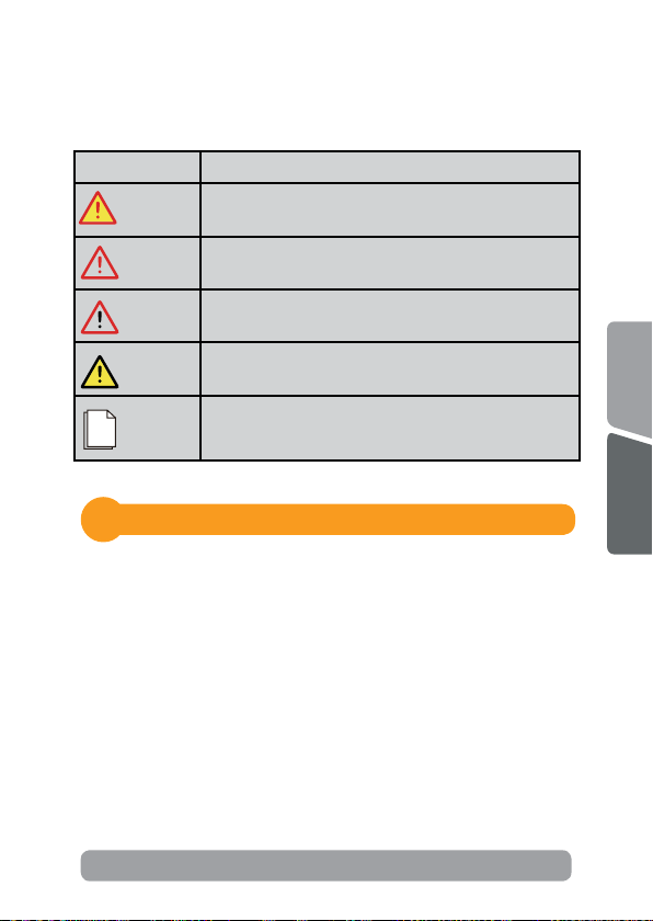
Symbol Convenons
The following safety instrucons and general informaon are used within
this user manual.
Symbol Description
DANGER Indicates an imminently hazardous situaon which, if not
correctly followed, will result in serious injury or death.
WARNING Indicates a potenally hazardous situaon which, if not
correctly followed, could result in serious injury or death.
CAUTION Indicates a potenally hazardous situaon which, if not
correctly followed, could result in moderate or minor injury.
NOTICE Indicates a potenally hazardous situaon which, if not correctly
followed, could result in equipment failure, or property damage.
NOTE
Calls aenon to important informaon, best pracces and
ps: supplement addional safety instrucons for your beer
use of the PV inverter to reduce the waste of your resource.
Safety
1
Before using the inverter, please read all instrucons and cauonary
markings on the unit and manual.
Put the instrucons where you can take them easily.
The ESS inverter of ours strictly conforms to related safety rules in design
and test. Local safety regulaons shall be followed during installaon,
operaon and maintenance. Incorrect operaon work may cause injury
or death to the operator or a third party and damage to the inverter and
other properes belonging to the operator or a third party.

3
1.2 Safety Precauon
1.1 Symbols Used
• Installaon,maintenance and connecon of inverters must be
performed by qualied personnel, in compliance with local electrical
standards, wiring rules and requirements of local power authories
and/or companies
• To avoid electric shock, DC input and AC output of the inverter
must be terminated at least 5 minutes before performing any
installaon or maintenance.
• The temperature of some parts of the inverter may exceed 60°
Symbol Description
Danger of high voltage and electric shock!
Only qualied personnel may perform work on the inverter.
Danger of high voltage. Residual voltage in the inverter need
5 mins to discharge, wait 5 mins before operaon.
Danger of hot surface
Fire danger
Environmental Protecon Use Period
Refer to the operang instrucons
Product should not be disposed as household waste
Grounding terminal
5 mins

4
English
Română
during operaon. To avoid being burnt, do not touch the inverter
during before touching it.
• Ensure children are kept away from inverters.
• Don’t open the front cover of the inverter. A part from performing
work at the wiring terminal (as instructed in this manual), touching
or changing components without authorizaon may cause injury to
people, damage to inverters and annulment of the warranty
• Stac electricity may damage electronic components. Appropriate
method must be adopted to prevent such damage to the inverter;
otherwise the inverter may be damaged and the warranty annulled.
• Ensure the output voltage of the proposed PV array is lower than
the maximum rated input voltage of the inverter; otherwise the
inverter may be damaged and the warranty annulled.
• When exposed to sunlight, the PV array generates dangerous high
DC voltage. Please operate according to our instrucons, or it will
result in danger to life.
• PV modules should have an IEC61730 class A rang.
• If the equipment is used in a manner not specied by the
manufacturer, the protecon provided by the equipment may be
impaired.
• Completely isolate the inverter before maintaining. Completely
isolate the inverter should: Switch o the PV switch, disconnect
the PV terminal, disconnect the baery terminal, and disconnect
the AC terminal.
• Prohibit to insert or pull the AC and DC terminals when the
inverter is running.
• Don’t connect ESS inverter in the following ways:
• EPS Port should not be connected to grid;
• The single PV panel string should not be connected to two or more
inverters.
5
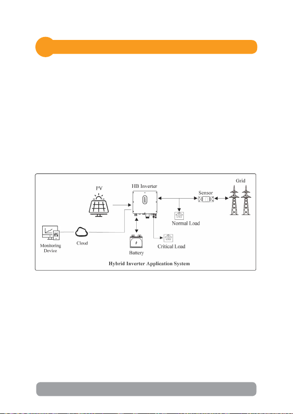
The hybrid inverters are high-quality inverter which can convert solar
energy to AC energy and store energy into baery.
The inverter can be used to opmize self consumpon, store in the baery
for future use or feed into public grid. Work mode depends on PV energy
and user’s preference. It can provide power for emergency use during the
grid lost by using the energy from baery and inverter (generated from
PV).
2.1 Overview
Hybrid Inverter
Product Introducon
2

6
English
Română
The AC couple inverters are high-quality inverter which can store energy
into baery.
The inverter can be used to opmize self consumpon, store in the baery
for future use or feed into public grid. Work mode depends on the baery
and user’s preference. It can provide power for emergency use during the
grid lost by using the energy from baery.
AC Couple Inverter
7
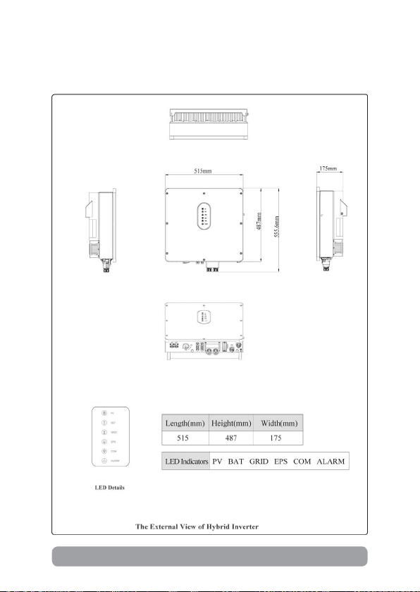
2.2 Product Appearance
2.2.1 Hybrid Inverter

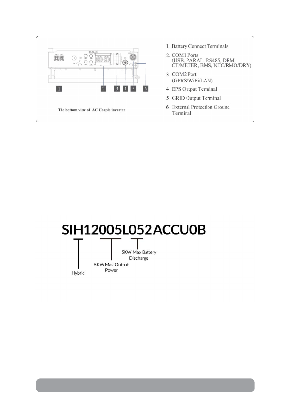
9
The leers in the product model have the specic informaons.
(Take SIH12005L052ACCU0B - Ascet 5K-120/1P2T2 as example.)
NOTE!
The appearances of hybrid inverter and AC couple inverter are presented in
detail in this secon. The following chapters are only illustrated by hybrid
inverter.
2.3 Model Denion

11
4
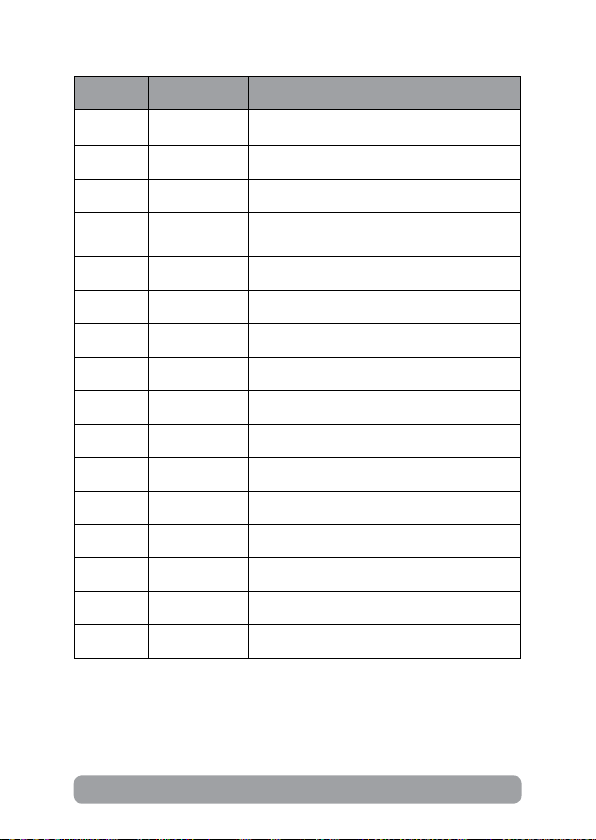
Number Quanty Descripon
A 1 Inverter
B 1 Mounng bracket
C 1 File package
D 2/2 PV terminal connector group (PV+/PV-) ;
N/A for AC Couple
E1EPS connector
F 1 Grid connector
G 2 Baery connector
H 1 Meter (Oponal)
I 1 CT
J 3 M12 Expansion screws
K 1 M6 Security screw
L 1 GPRS/WiFi module (Oponal)
M19-Pins terminal
N 2 4-Pins terminal
O 1 Removal tool for PV connector
P 1 Removal tool for Grid/EPS connector
12
English
Română
3.2 Selecng the Mounng Locaon
3.2.1 Installaon Environment Requirements
a. The storage inverter protecon class is IP65 and can be mounted
indoors or outdoors.
b. The mounng locaon must be inaccessible to unrelated personnel
since the enclosure and heat sinks are extremely hot during operaon.
c. Do not install the storage inverter in areas containing highly ammable
materials or gases.
d. To ensure opmum operaon and long service life, the ambient
temperature must be below 50°C.
e. The storage inverter must be mounted in a well venlated environment
to ensure good heat dissipaon.
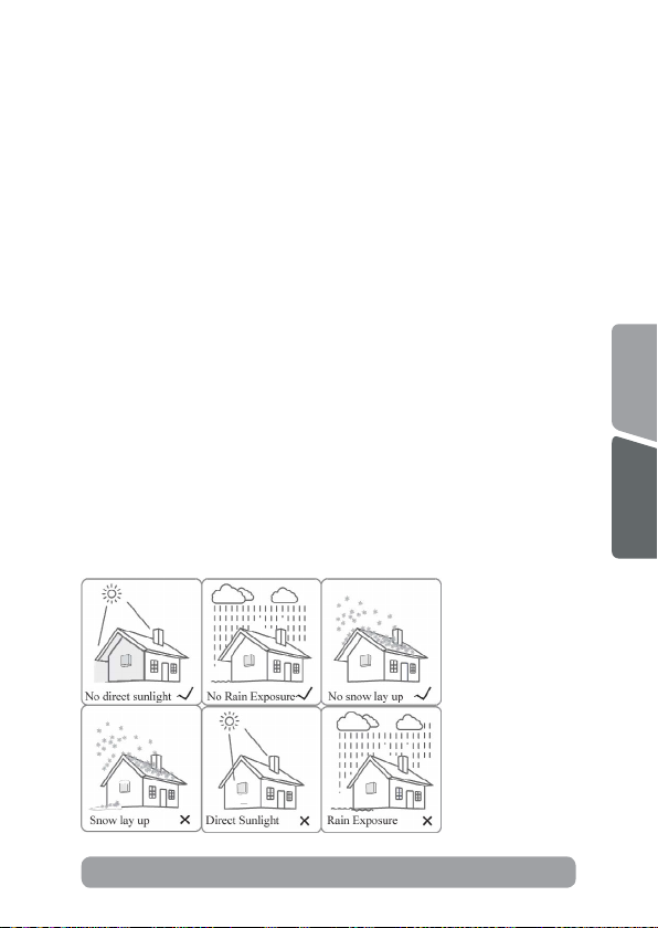
f. To ensure long service life, the storage inverter must not be exposed to
direct solar irradiaon, rain, or snow. It is recommended that the inverter
be mounted in a sheltered place.
g. The carrier where the inverter is mounted must be re-proof. Do not
mount the inverter on ammable building materials.
h. Do not install the inverter in a rest area since it will cause noise during
operaon.
i. The installaon height should be reasonable and make sure it is easy to
operate and view the display.
j. Product label and warning symbols shall be clear to read aer installaon.
k. Please avoid direct sunlight, rain exposure, show lay up install.
13
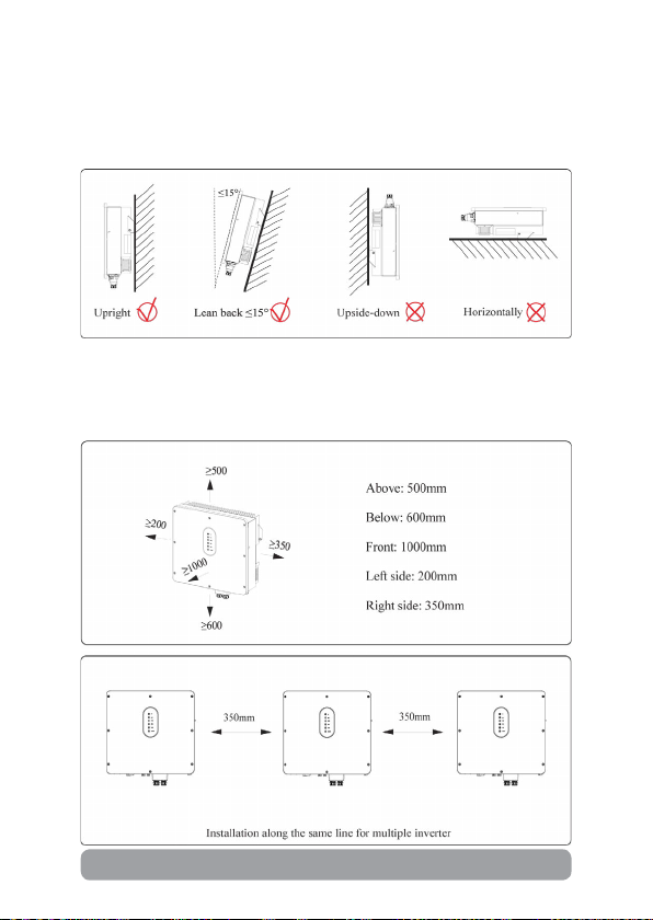
3.2.2 Mounng Requirements
3.2.3 Installaon Space Requirements
To ensure the inverter normally and easy to operate, there are requirements
on available spaces of the inverter, e.g. to keep enough clearance. Refer
to the following gures.
Mount the inverter vercally or lted backward by max 15°. The device
can not be installed with a wrong mode and the connecon area must
point downward.
14
English
Română
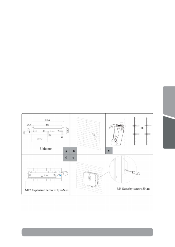
Before mounng the inverter, you have to prepare expansion
bolts(specicaon: M12*80; Quanty: 3).
Step 1. Install the mounng bracket
1. Use a level ruler to mark the posion of the 3 holes on the wall. Refer
to Figure a. and drill 3 holes, 16mm in diameter and 55mm in deep. Refer
to Figure b.
2. Knock the expansion screw kit into the hole together with a hammer.
Refer to Figure c.
Note: Do not remove the nut unit in Figure c.
3. Aer ghtening 2-3 buckles, the expansion bolts are ght and not
loose, and then unscrew the bolts, spring washer, gasket. Refer to Figure c.
4. Install and x the mounng bracket on the wall. Refer to Figure d.
Step 2. Install the inverter on the mounng bracket. Then lock the
inverter using the security screw. Refer to Figure d.
3.3 Mounng

15
To prevent potential damages and injuries from inverter falling
down, please hang the inverter on the bracket, do not loosen grip
unless conrm the inverter is well mounted.
CAUTION
Before drilling the hole on the wall, ensure no damage on the
electric wire and/or water pipe inside the wall.
Danger
4.1 Inverter’s setup connecon
This chapter shows the details connecon of ESS inverter. The following
illustraon only uses the hybrid inverters as an example.
ESS inverter system connecon diagram:
Electrical Connecon
4


17
Single phase parallel connecon mode-Scheme A (N≤5)
This manual suits for next models
7
Table of contents
Languages:
Other Njoy Inverter manuals


Popular Inverter manuals by other brands


Mitsubishi Electric
Mitsubishi Electric fr-e700 series instruction manual

Mitsubishi Electric
Mitsubishi Electric A800-E instruction manual

Deye
Deye SUN-3K-G03-1 user manual

Kostal
Kostal PIKO 4.2 operating manual

MULTIQUIP
MULTIQUIP Power WHISPERWATT DCA-45SSIU2 Parts and operation manual

Thiele
Thiele YK-PSW5KVA Series user manual