Norsonic nor1217 User manual
INSTRUCTION
MANUAL
Outdoor microphone
nor1217


Outdoor microphone
nor1217

Nor1217 – User Guide
Im1217_1Ed1R1En – November 2013 edition
Norsonic is a registered trademark of Norsonic AS.
Every effort has been made to supply complete and ac-
curate information. However, Norsonic AS assumes no
responsibility for the use of – or for the consequential dam-
age resulting from the use of – this information and/or the
instrumentation described herein. Furthermore, Norsonic AS
assumes no responsibility for any infringement of the intel-
lectual property rights of third parties, wherever applicable,
which could result from such use.
Norsonic AS reserves the right to amend any of the informa-
tion given in this manual in order to take account of new
developments.
If you wish to communicate with us, please feel welcome
Our address is:
Norsonic AS, P.O. Box 24, N-3421 Lierskogen Norway,
Find us on the web: www.norsonic.com
Tel: +47 3285 8900
Fax: +47 3285 2208
E-mail: [email protected]
Copyright © Norsonic AS 2013
All rights reserved

v
Norsonic Nor1217
Instruction Manual
v
Contents
Chapter 1 Introduction ......................................................................................................... 1
Chapter 2 Assembling .......................................................................................................... 2
Grounding and lightning protection 3
Chapter 3 Microphone calibration....................................................................................... 4
Chapter 4 Technical description.......................................................................................... 5
Electrical description 6
System check 7
Frequency response 9
Self-noise 10
Cables and cable length 11
Directional response 12
Frequency response 13
Self-noise and wind 14
Chapter 5 Connecting the Nor1217 to Sound Analyser Nor140...............................................15
Chapter 6 Maintenance........................................................................................................17
Chapter 7 Specifications .....................................................................................................18
Mounting direction 18
Acoustic performance 18
General 18
Frequency response 18
Directional response 18
General 18
Conformity 19
Protection provided by the enclose 19
Accessories and spare parts 19


1
Norsonic Nor1217
Instruction Manual
1
Introduction
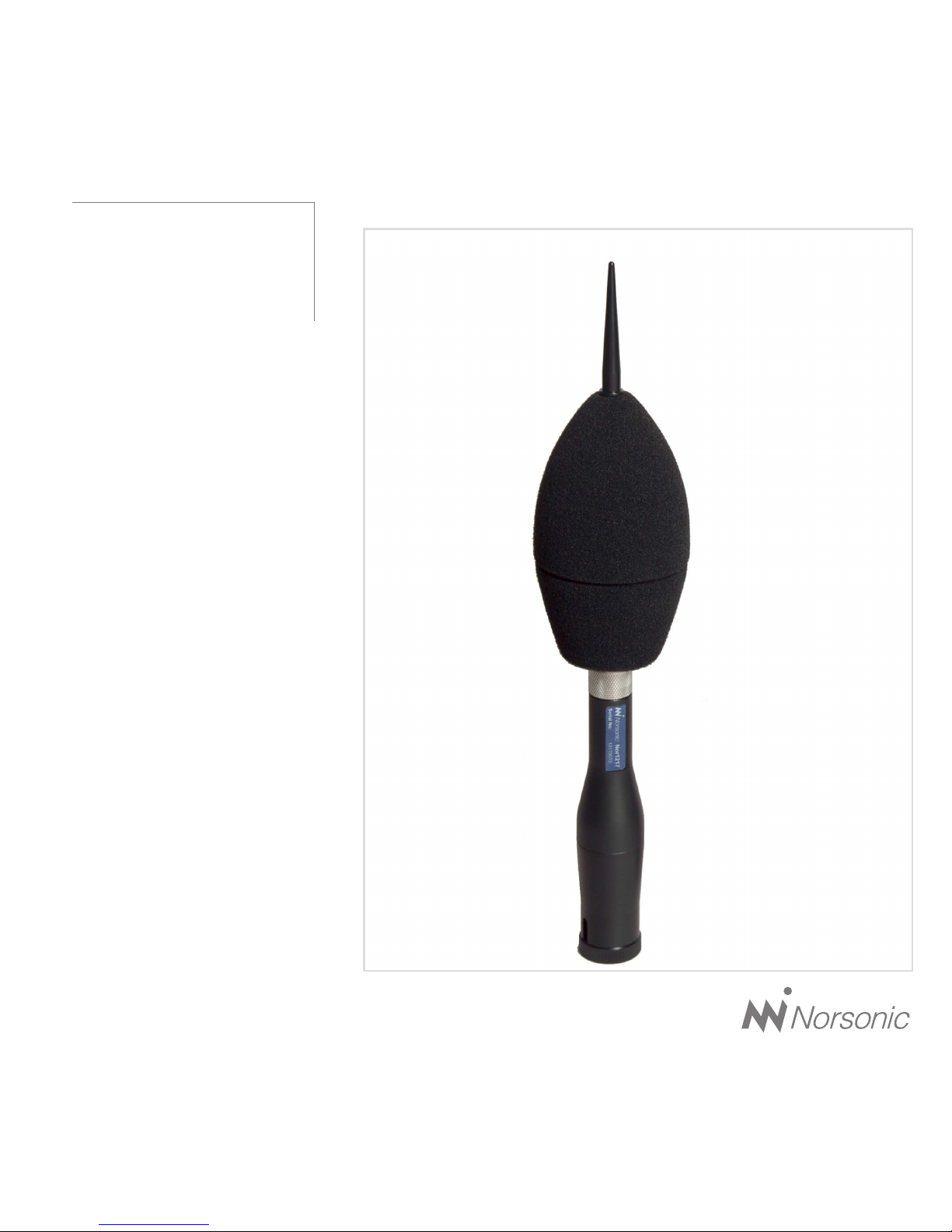
The outdoor microphone Nor1217 is a measurement
microphone protection kit for all-weather conditions. It
is mainly intended for temporary outdoor applications.
The microphone contains elements for protecting the
microphone cartridge from rain, snow, dust and insects,
satisfying IP 55 requirements. The Protection kit is
designed for use with the preamplifier Nor1209 and one
of the microphones Nor1225 or Nor1227.
Further, compared to a standard measurement micro-
phone, the Nor1217 improves the measurement accu-
racy by reducing the wind noise and by improving the
directional response for sound from different directions.
Combined with a suitable sound level meter including
a frequency response correcting function, the Nor1217
satisfy Class 1 specification requirements according to
IEC61672-1 and similar national standards for a sound
level meter class 1.
The microphone is intended for vertical mounting only
since the act of gravitation forms a part of the rain pro-
tection system. The reference direction may, however,
be selected to be vertical or horizontal based on the
applied frequency response compensation in the sound
level meter.
The outdoor microphone may be calibrated with a
normal sound calibrator suitable for ½” working stand-
ard microphones (WS2) and without the need for extra
accessories. Access to the microphone cartridge is
easily gained by dismounting the upper part of the
outdoor microphone.
The base of the Nor1217 is made of an electrical insulat-
ing material. The microphone body will be fully insulated
from the mounting mast thereby reducing pick-up of
electrical hum and noise.
The preamplifier Nor1209 used in the Nor1217 kit is
equipped with the standard 7-pin Lemo connector for
microphone preamplifiers. For verification of proper
operation, the preamplifier is equipped with a system
check facility, where an electrical signal applied on one
of the terminals are returned after passing through the
complete signal chain, thus verifying proper operation
of the microphone cartridge, preamplifier and micro-
phone cable.
Nor1217 is mainly designed to be used with the Nor140
Sound Analyser. This instrument has the requested fre-
quency compensation and delivers the required current.

2Chapter 2
Assembling
Assembling
The outdoor microphone Nor1217 normally shipped
without preamplifier and microphone, since these parts
is normally taken from the Nor140 Sound Analyser.
Depending on the application, you will need a mast
or tripod for mounting the microphone system and
possibly devices for proper grounding and lightning
protection, see below.
We recommend cable type Nor1408A, which
comes in standard lengths of 5, 10, 15, 20, 30 and 50
metres – other lengths are available on request. This
cable is Teflon®-insulated and hence absorbs very lit-
tle water, which is very important in order to retain high
insulation in all weather conditions. The mantle is made
of polyurethane to ensure a robust cable, yet flexible at
low temperatures.
Birdspike
Wind, dust and
water protection
Upper part
Microphone cartridge
Microphone preamplifier
Nor1209
Base
Connector/cable
Optional tripod adaptor
with tension relief
O-ring
NOTE: You need to use the “A” version
of the 1408 cable (1408A). The cable
comes with a threaded female connec-
tor housing that fits to the 1209 preamp-
lifier lock nut. Older versions (not “A”) of the ca-
ble do not have this treads and will not fit into the
microphone kit. The rubber protection covering
the female connector housing must be removed
in order to fit into the microphone kit.

3
Norsonic Nor1217
Instruction Manual
Unscrew and remove the upper part consisting of
birdspike and windscreen as one unit. Do not remove the
windscreen from this upper part as this may destroy the
weather protection and alter the acoustic performance.
The unit is delivered with an adaptor for mounting
on a tripod. The cable is led through a slot in the side of
the adaptor. The base screw has a threaded hole like
those commonly used for cameras (3/8” UNC). The
base screw also forms a tension relief for the cable.
Remove the base screw and slide the cable through
the base unit. Assemble the microphone cartridge to
the preamplifier and connect the preamplifier to the
cable. We recommend to mount the supplied O-ring
between the microphone cartridge and the preamp-
lifier. Screw the lock nut on the preamplifier onto the
female connector on the 1408A cable. Push the pre-
amplifier carefully into the base unit. The preamplifier
and microphone is aligned in the correct position by
a spring force. After mounting the upper protection
part, the outdoor microphone unit will be ready for use.
However, we recommend that you test the unit togeth-
er with the measuring instrument by applying a calibra-
tor before the upper part is mounted.
Grounding and lightning protection
If the outdoor microphone assembly is the highest ob-
ject in the vicinity when mounted, it may be exposed
to lightning strokes. We recommend to use a conduc-
tivemast and to ground it properly. A rod in proper con-
tact with the conductive mast should be made at the
side and 50 cm above the tip of the microphone. The
rod should be placed at least 25 cm to the side of the
microphone assembly and have a diameter not more
than 10 mm in order not to interfere with the directional
properties of the microphone.
Safety considerations may require the screen of the
microphone cable to be properly grounded and that
the internal conductors are clamped for high voltage
protection.
We recommend making the combined grounding
for the cable and instrument at one point only in order
to reduce the risk of pick-up of hum and electromag-
netic noise.
Verify the noise floor of the complete system after
installation is completed to ensure it is below the lower
end of the required measurement range. If a quiet lo-
cation is not available, the noise floor may be meas-
ured by substituting the microphone with a dummy mi-
crophone like Nor1448. As an alternative the Nor1447
adaptor terminated with a short-circuit or a 50 ohm
BNC termination is also a suitable device for making
this test. A sound calibrator in OFF-mode may also be
used to attenuate the external noise. A ½” microphone
normally requiring polarization voltage may also be
used without polarization voltage. It will then have a
very low sensitivity.
NOTE: Please note that the System
Check signal must be deactivated when
you want to calibrate the microphone with
an acoustical calibrator. Unless deacti-
vated, you will read unstable values due to the
interference between the System Check signal
and the signal from the sound calibrator.

4Chapter 3
Microphone calibration
Microphone calibration
The Nor1217 can be calibrated with a sound calibra-
tor for ½” microphones without the need for special
couplers. We recommend using Nor1251 (1000 Hz) or
Nor1253 (250 Hz).
Unscrew the upper part of the microphone to gain
access to the microphone cartridge. Mount the cali-
brator slowly and carefully while turning the calibrator
and switch it on. See figure.
If the calibrator frequency is 250 Hz, adjust the
reading to be the level stated for the calibrator, e.g.
124,0 dB for Nor1253 with 124 dB specified level.
If the calibrator frequency is 1000 Hz, adjust the
reading to be 0,1 dB below the stated calibrator level,
e.g. 113,9 dB for Nor1251 calibrator with a stated level
of 114 dB.
This is only valid if the frequency response correc-
tion is turned off. For the Nor140 the frequency cor-
rection is turned off, when entering into the calibration
menu. Perform calibration and calibrate the micro-
phone as a normal free field microphone. I.E. -0.1 dB
if using a 1000 Hz calibrator. When leaving the cali-
bration menu, you will observe that the level measured
with the calibrator on, is different from what obtained
in the calibration mode. This is correct, and is due to
the frequency correction added. If horizontal position
is selected, the signal will be about 0.1 dB higher than
the calibrated signal, in vertical position the signal will
be 0.3 dB lower than the calibrated level. This does
not apply if you calibrate with a 250 Hz calibrator since
there is no correction added at this frequency.

5
Norsonic Nor1217
Instruction Manual
Technical description
The outdoor microphone Nor1217 is based on a ½”
working standard microphone type WS2F according
to IEC 61094-4.
Two types of microphones is tested and is recom-
mended;
- Nor1225, a free field microphone requiring 200V
polarisation voltage.
- Nor1227, a free field self polarised microphone.
Both microphones have a nominal sensitivity of 50 mV/P
a. However, each microphone is individual calibrated
and may differ slightly from this value.
The upper part of the Nor1217 consists of wind-
screen, rain hood, dust mesh and birdspike and pro-
tects the microphone from rain, snow, dust and insects.
Both the rain hood and the dust mesh are made of a
water-repellent fabric open for the sound. The sound
is reaching the microphone through nine slots placed
equidistantly around the circumference of the circular
body of the upper part. The mechanical part with the
birdspike is also important for the directional response
of the complete microphone system.
The upper part may be removed as one unit and will
thus give easy access to the microphone cartridge for
testing and calibration.
Birdspike
Windscreen
Microphone cartridge
Rain hood
Dust mesh
Preamplifier
Plate for type and
serial number
Base
Unscrew the
upper part
here!
Upper part

6Chapter 4
Technical description
The lower part consists of the base, the microphone
cartridge and the preamplifier Nor1209. A normal mi-
crophone cable supplied with Norsonic sound level
meters, like Nor1408A, should be used for connec-
tion to the sound level meter instrument. An adaptor
for mounting the outdoor microphone on a tripod is
included.
The base is made of black polyacetal (POM). The
material is durable and insulating, thus preventing
electric noise from ground loops through the mast.
Drops of water from rain are kept away from the mi-
crophone diaphragm by the combined act of the tubu-
lar windscreen, the rain hood and the dust mesh. The
upper part of the microphone cartridge is air- and wa-
ter tight, and the backside is vented to the air through
the preamplifier.
The Ingress Protection Category for the assembled
microphone is IP55 according to IEC 60529.
Consider the assembly of microphone cartridge
and preamplifier as a single unit when operated in the
field. If disassembled in the field, the performance may
be reduced due to contamination from dust and hu-
midity.
When Nor1217 substitutes a normal measurement
microphone on a sound level meter, a correction of the
frequency response is needed to retain the class of
accuracy for the sound level meter, see Specifications.
Based on the correction, the reference direction may
be selected to be either horizontal or vertical. Horizon-
tal reference direction is usually selected for sound
approaching the microphone mainly along a horizon-
tal axis like noise from industry or vehicles. A vertical
reference axis is usually used for measuring the noise
from aircraft.
The sound analyser Nor140 has a correction net-
work where the reference axis for the outdoor micro-
phone Nor1217 may be selected to be horizontal or
vertical
See separate description in this manual on how to con-
figure the Nor140, Chapter 5.
Electrical description
The power to the Nor1217 will normally be supplied
from a Norsonic sound analyser Nor140 instrument
and the user does not need detailed knowledge of the
interconnection. Alternatively, the microphone unit may
be supplied either from a single supply in the range 28
V to 120 V or a symmetric supply in the range ±14 V to
±60 V. The latter alternative is recommended. Required
current is 3mA. The connection is shown on the adjacent
figure. (Outside view for the connector).
Pin 3, allocated for polarization voltage, shall be ter-
minated to signal ground (pin 2) for the microphone
cartridge Nor1227. When the microphone unit is
equipped with the Nor1225 microphone cartridge where
polarization voltage is needed, 200 V must be supplied
to this terminal.
Rain hood
Microphone
cartridge
Dust mesh
Wind screen

7
Norsonic Nor1217
Instruction Manual
The supply voltage will affect the maximum sound pres-
sure that can be measured. For ±15 V or +30 V supply,
the maximum peak value exceeds 10 volt corresponding
to 140 dB peak sound pressure level for the Nor1227 /
Nor1225 microphone cartridge (50mV/Pa).
By the use of the “high level” option in Nor140, signals
with peak values up to 150 dB may be measured with
the microphone cartridge Nor1225.
The figure below shows a simplified electrical circuit
diagram of the complete outdoor microphone. The
microphone cartridge is connected to the preamplifier
input terminal. The figure below shows the output con-
nector seen from outside.
1
2
3
4
5
7
6
Signal ground
Polarization voltage
Signal output
Not connected
Power supply +
Power supply -
5
6
1
4
3
7
2
V+
NC
System check
Output
Heater
resistor
Vpol
V-
GND
System check
The system check terminal, pin 1, shall be termi-
nated to signal ground or the signal output when the
microphone system is in normal use. For checking the
system, a test signal may be supplied, e.g. an AC sig-
nal of 1 volt – 1000 Hz. The signal is transmitted to the
preamplifier input through a capacitor with a very low
capacitance (about 0.8 pF) and further to the signal
output.
The system check is a robust and simple method
for verifying a microphone system. It measures the
change in the capacity of the microphone cartridge.
Nominal cartridge capacity of a ½” microphone is
18 pF. The test signal is feed through a fixed 0,8 pF
capacitor, and the system check voltage is measured
as a function of the attenuation between the 0,8 pF ca-
pacitor and the microphone cartridge with a nominal
capacitance of 18 pF.

8Chapter 4
Technical description
A typical level for the returned signal is 45 mV with
an excitation of 1 volt corresponding to a sound level
of 92 – 95 dB dependant of the microphone cartridge
capacitance. The signal may be used for verification of
correct operation of the cable and preamplifier. Even
a malfunctioning microphone may be detected since
this is normally accomplished by a change in the mi-
crophone capacitance. A very low signal is returned in
case of a short-circuit in the microphone.
A 200 V polarised microphone will show approxi-
mately 2 dB higher level if the 200 V disappear due to
the lost tension and thereby decreased capacity in the
diaphragm when the 200 V is off.
The sound analyser Nor140 has a build-in signal
generator that delivers the required signal for system
check. The signal is switched on/off from the instru-
ment menu. See separate description.
Pin 1, System
Check input Pin 4,
Output
Pin 2,
Ground
Microphone cartridge 18pF
0,8pF
9
Norsonic Nor1217
Instruction Manual
0.1
1 10 100
Frequency [Hz]
1k 10k 100k
8
7
6
5
4
3
2
1
0
1
2
dB
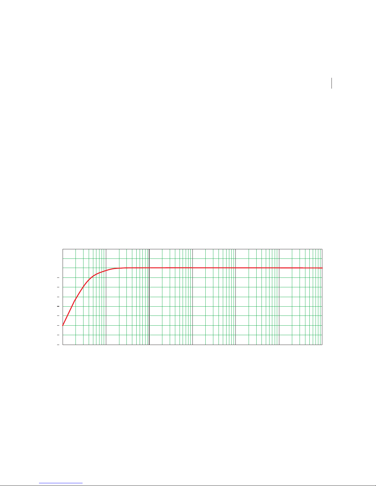
Typical frequency response for the preamplifier Nor1209A
Frequency response
The typical frequency response for the preamplifier
Nor1209 is shown below. The frequency response for
the outdoor microphone system is therefore mainly de-
termined by the microphone cartridge and the acous-
tic performance of the enclosure.

10 Chapter 4
Technical description
-10.0
-5.0
0.0
5.0
10.0
15.0
20.0
6.3 Hz
8.0 Hz
10 Hz
12.5 Hz
16 Hz
20 Hz
25 Hz
31.5 Hz
40 Hz
50 Hz
63 Hz
80 Hz
100 Hz
125 Hz
160 Hz
200 Hz
250 Hz
315 Hz
400 Hz
500 Hz
630 Hz
800 Hz
1.0 k
1.25 k
1.6 k
2.0 k
2.5 k
3.15 k
4.0 k
5.0 k
6.3 k
8.0 k
10.0 k
12.5 k
16.0 k
20.0 k
A C
Frequency [Hz] / Network
Level [dB]
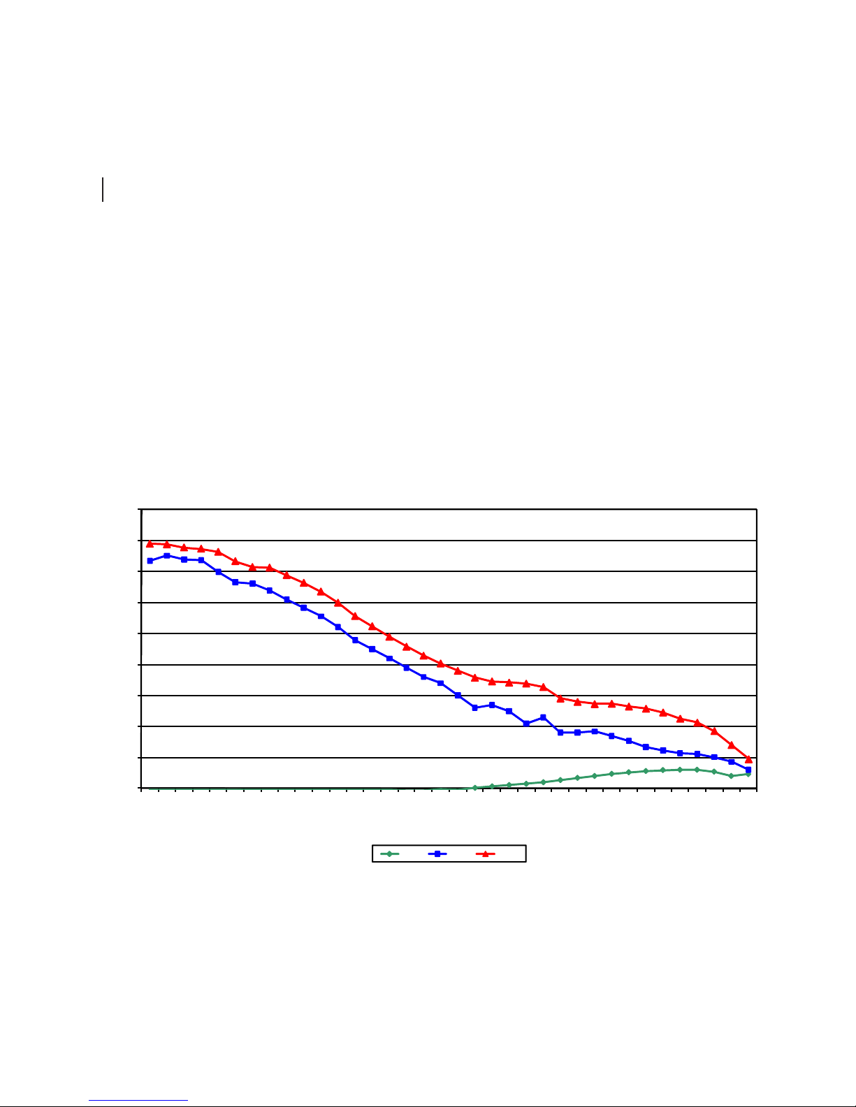
Self-noise
The electrical noise when the microphone is substi-
tuted by an 20 pF capacitor is shown on the graph be-
low. 0 dB corresponds to 1 µV. For a microphone with
a sensitivity of 50 mV/Pa (Nominal value of Nor1225/
Nor1227), 0 dB voltage also corresponds to the normal
reference pressure for sound: 20 µPa and the noise
level may be compared with sound pressure level di-
rectly.
Typical self noise of the microphone system when the microphone is substituted by a capacitor with similar
capacitance as the microphone. Note that the acoustical self-noise for a real microphone will be higher due to
thermal noise in the microphone cartridge.
11
Norsonic Nor1217
Instruction Manual
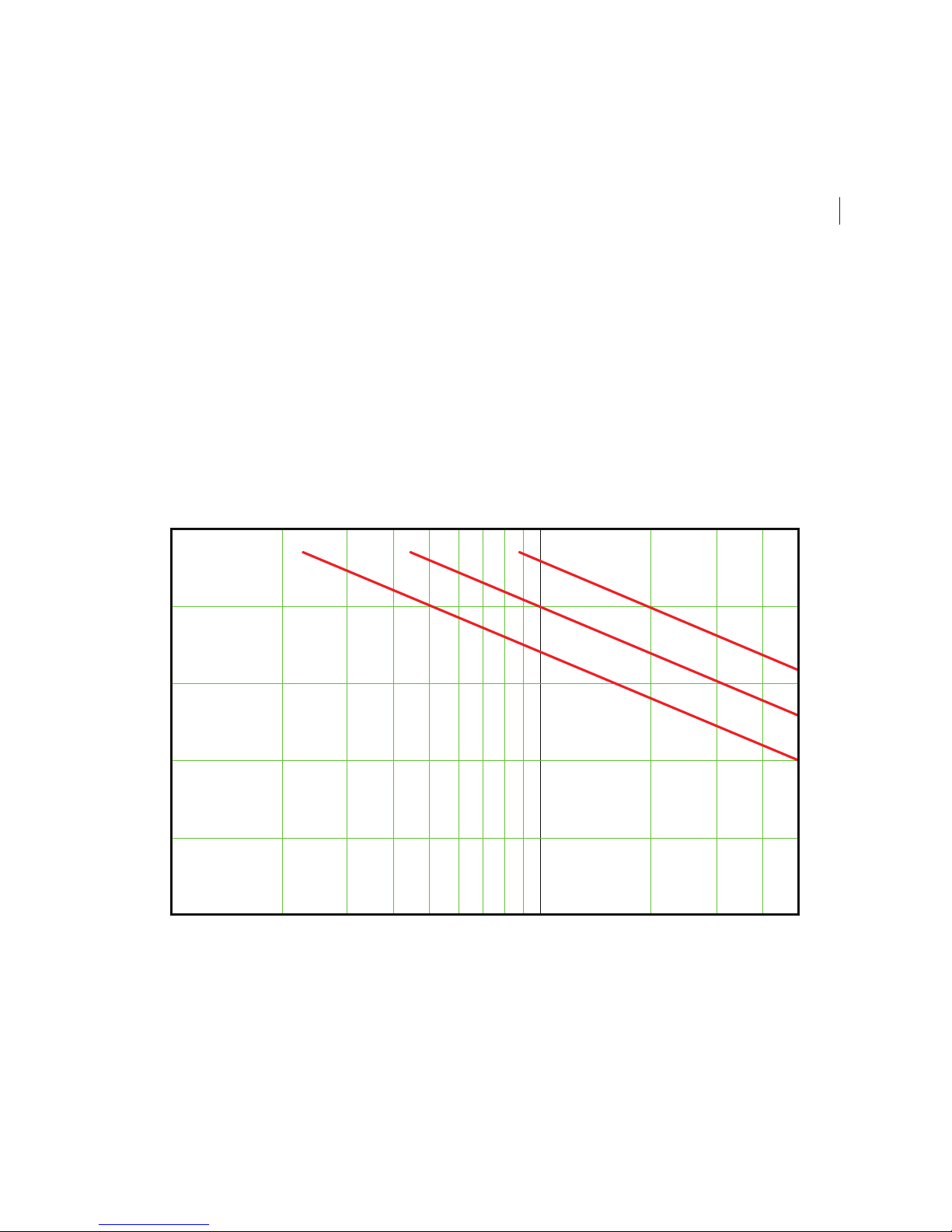
140
130
120
110
100
90
10 m 50 m 100 m20 m 200 m 500 m
20 kHz
10 kHz
5 kHz
dB
Cable length (120 pF/m)
Level
Cables and cable length
The Nor1217 with its preamplifier Nor1209 has excel-
lent driving capability for long cables. The signal output
from the microphone preamplifier will be loaded by the
capacitance of the cable between the microphone sys-
tem and the instrument. The capacitance will increase
proportionally with the length of the cable. A typical
value for microphone cables from Norsonic is 120 pF
per metre. Hence, a cable with length 100 m, will load
the output with a capacitance of 12 nF. For lower fre-
quencies there are seldom problems with long cables.
However, when the signal contains the combination
of high amplitude and high frequency, the capacitive
loading will lead to high output current. A limited cur-
rent capacity will set limits for the maximum slew-rate
for the signal. The figure below shows the maximum
level as function of cable length and frequency. 20 kHz
corresponds to the bandwidth of the microphone sys-
tem with the normal microphone Nor1225 or Nor1227..

12 Chapter 4
Technical description
100 10 k 20 k
1 k
0
1
2
3
4
Frequency [Hz]
+/- 30 deg – Horizontal reference
Directional response
An outdoor microphone system like Nor1217 may
form a part of a sound level meter when applied for
environmental noise monitoring. The combination of
microphone and instrument shall therefore satisfy all
requirements in the international standards for sound
level meters, specified in IEC 61672-1. The Nor1217
in combination with Nor140 is type approved by PTB,
Germany. Ideally, the microphone shall have the same
sensitivity for sound from any direction. The IEC 61672-
1 specifies tolerance limits for the directional response.
The directional response of a microphone is the ratio
of the free field response at a particular frequency as
a function of angle of sound incidence to the response
in the reference direction.
The upper adjacent figure shows the directional re-
sponse for Nor1217, when the reference axis is verti-
cal, for the frequencies 1000 Hz, 4000 Hz and 8000
Hz.
IEC 61672-1 specifies tolerance limits for any frequen-
cy. The limits are depending on the angle from the ref-
erence axis and the standard specify tolerance limits
for angles up to ± 30°, up to ± 90° and up to ± 150°
from the reference axis. The lower adjacent figure
shows the typical max. deviation for the sector up to
± 30° from a horizontal reference axis together with the
applicable tolerance limits for a Class 1 sound level
meter.

13
Norsonic Nor1217
Instruction Manual
Frequency response
The figure below shows the typical frequency re-
sponse for sound approaching the microphone in two
directions. The response marked “Vertical” is the re-
sponse for sound approaching the microphone from
above along the bird spikes, when the microphone is
in the recommended vertical direction. The response
marked “Horizontal” is the response for sound ap-
proaching the microphone in a horizontal direction
when the microphone is mounted in the same recom-
mended vertical direction.
Due to the lower sensitivity for higher frequencies, as
shown on the figure, it is recommended to correct the
frequency response to ensure that the response is
within the requirement for Class 1 sound level meters
specified in the international standard IEC 61672-1.
10 10 0 1k 10 k 20 k
30−
25−
20−
15−
10−
5−
0
5
10
Vertical
Horizontal
Sensitivity level [dB]
Frequency [Hz]
When the microphone system is used in connection
with the precision sound analyser Nor140 (for program
version 3.0 and above), just select 1214/1216/1217
Vertical or Horizontal in the input setup menu to enable
the right settings. Turn the polarization voltage On if
you use a Nor1225 and Off if you use a Nor1227.
When used with Nor118 we recommend the following
corrections:
Vertical: Random response correction (R) and
Windscreen correction (W)
Horizontal: Random response correction (R)
Please note that the frequency compensation applied
using the Nor118 does not fulfil the class 1 require-
ments, but is just a “best fit” method.
14 Chapter 4
Technical description
Self-noise and wind
The figure below shows typical self-noise for the mi-
crophone system as levels for the various 1/3-octave
frequency bands re. 20 µPa when the microphone is
placed in a horizontal, laminar flow of air with speed 0,
5 and 10 m/s, respectively. The levels are measured
without frequency compensation. The correspond-
ing A-weighted levels are 16 dB, 40 dB and 48 dB.
Depending on the wind speed, the noise levels are
typically 20 dB to 30 dB lower than for an unprotected
microphone.
0
10
20
30
40
50
60
70
80
90
6,3
8
10
12,5
16
20
25
31,5
40
50
63
80
100
125
160
200
250
315
400
500
630
800
1 k
1.25 k
1.6 k
2 k
2.5 k
3.15 k
4 k
5 k
6.3 k
8.3 k
10 k
12.5 k
16 k
20 k
Sound pressure level [dB]
1/3 octave frequency band [Hz]
0 m/s 5 m/s 10 m/s
Table of contents
Other Norsonic Microphone manuals


