Norsonic nor1218 User manual

INSTRUCTION
MANUAL
Outdoor microphone
nor1218


Outdoor microphone
nor1218

Nor1218 – User Guide
Im1218_1Ed1R1En – January 2015 edition
Norsonic is a registered trademark of Norsonic AS.
Every effort has been made to supply complete and ac-
curate information. However, Norsonic AS assumes no
responsibility for the use of – or for the consequential dam-
age resulting from the use of – this information and/or the
instrumentation described herein. Furthermore, Norsonic AS
assumes no responsibility for any infringement of the intel-
lectual property rights of third parties, wherever applicable,
which could result from such use.
Norsonic AS reserves the right to amend any of the informa-
tion given in this manual in order to take account of new
developments.
If you wish to communicate with us, please feel welcome
Our address is:
Norsonic AS, P.O. Box 24, N-3421 Lierskogen Norway,
Find us on the web: www.norsonic.com
Tel: +47 3285 8900
Fax: +47 3285 2208
E-mail: [email protected]
Copyright © Norsonic AS 2014
All rights reserved

v
Norsonic Nor1218
Instruction Manual
v
Contents
Chapter 1 Introduction ......................................................................................................... 1
Chapter 2 Assembling .......................................................................................................... 2
Grounding and lightning protection 3
Chapter 4 Microphone calibration....................................................................................... 4
Chapter 5 Technical description.......................................................................................... 5
Frequency response 7
Self-noise 8
Cables and cable length 9
Directional response 10
Frequency response 11
Self-noise and wind 12
Chapter 6 Connecting the Nor1218 to Sound Level Meter Nor131 or
Environmental Noise Meter Nor139 .............................................................................13
Chapter 7 Maintenance........................................................................................................14
Chapter 8 Specifications .....................................................................................................15
Mounting direction 15
Acoustic performance 15
General 15
Frequency response 15
Directional response 15
General 15
Conformity 16
Protection provided by the enclose 16
Accessories and spare parts 16


1
Norsonic Nor1218
Instruction Manual
1
Introduction
The outdoor microphone Nor1218 is a measurement
microphone protection kit for all-weather conditions. It
is mainly intended for temporary outdoor applications.
The microphone contains elements for protecting the
microphone cartridge from rain, snow, dust and insects,
satisfying IP 55 requirements. The Protection kit is
designed for use with the IEPE preamplifier Nor1207
and one of the microphones Nor1227 or Nor1228.
Further, compared to a standard measurement micro-
phone, the Nor1218 improves the measurement accu-
racy by reducing the wind noise and by improving the
directional response for sound from different directions.
Combined with a suitable sound level meter including
a frequency response correcting function, the Nor1218
satisfy Class 1 specification requirements according to
IEC61672-1 and similar national standards for a sound
level meter class 1.
The microphone is intended for vertical mounting only
since the act of gravitation forms a part of the rain pro-
tection system. The reference direction may, however,
be selected to be vertical or horizontal based on the
applied frequency response compensation in the sound
level meter.
The outdoor microphone may be calibrated with a
normal sound calibrator suitable for ½” working stand-
ard microphones (WS2) and without the need for extra
accessories. Access to the microphone cartridge is
easily gained by dismounting the upper part of the
outdoor microphone.
The base of the Nor1218 is made of an electrical insulat-
ing material. The microphone body will be fully insulated
from the mounting mast thereby reducing pick-up of
electrical hum and noise.
Nor1218 is mainly designed to be used with the Nor131
and Nor139 Sound Level Meters. These instruments
have the requested frequency compensation and deliver
the required IEPE current.

2Chapter 2
Assembling
Assembling
The outdoor microphone Nor1218 is normally shipped
without preamplifier and microphone, since these
parts is normally shipped with the Sound Level Meter
Nor131 or Nor139.
Depending on the application, you will need a mast
or tripod for mounting the microphone system and
possibly devices for proper grounding and lightning
protection, see below.
We recommend cable type Nor4531, which comes
in standard lengths of 5, 10, 15, 30 and 50 metres –
other lengths are available on request.
Unscrew and remove the upper part consisting of
birdspike and windscreen as one unit. Do not remove
the windscreen from this upper part as this may de-
stroy the weather protection and alter the acoustic per-
formance.
The unit is delivered with an adaptor for mounting
on a tripod. The cable is led through a slot in the side of
the adaptor. The base screw has a threaded hole like
those commonly used for cameras (3/8” UNC). The
base screw also forms a tension relief for the cable.
Remove the base screw and slide the cable through
the base unit. Assemble the microphone cartridge to
the preamplifier and connect the preamplifier to the
cable. We recommend mounting the supplied O-ring
between the microphone cartridge and the preamp-
lifier.
Birdspike
Wind, dust and
water protection
Upper part
Microphone cartridge
Microphone preamplifier
Nor1207
Base
Connector/cable
Optional tripod
adaptor with tension
relief
O-ring

3
Norsonic Nor1218
Instruction Manual
Screw the lock nut on the preamplifier onto the fe-
male connector on the cable. Push the preamplifier
carefully into the base unit. The preamplifier and mi-
crophone is aligned in the correct position by a spring
force. After mounting the upper protection part, the
outdoor microphone unit will be ready for use. How-
ever, we recommend that you test the unit together
with the measuring instrument by applying a calibrator
before the upper part is mounted.
Grounding and lightning protection
If the outdoor microphone assembly is the highest ob-
ject in the vicinity when mounted, it may be exposed to
lightning strokes. We recommend to use a conductive
mast and to ground it properly. A rod in proper con-
tact with the conductive mast should be made at the
side and 50 cm above the tip of the microphone. The
rod should be placed at least 25 cm to the side of the
microphone assembly and have a diameter not more
than 10 mm in order not to interfere with the directional
properties of the microphone.
Safety considerations may require the screen of the
microphone cable to be properly grounded and that
the internal conductors are clamped for high voltage
protection.
We recommend making the combined grounding
for the cable and instrument at one point only in order
to reduce the risk of pick-up of hum and electromag-
netic noise.
Verify the noise floor of the complete system after
installation is completed to ensure it is below the lower
end of the required measurement range. If a quiet lo-
cation is not available, the noise floor may be meas-
ured by substituting the microphone with a dummy mi-
crophone like Nor1448. As an alternative the Nor1447
adaptor terminated with a short-circuit or a 50 ohm
BNC termination is also a suitable device for making
this test. A sound calibrator in OFF-mode may also be
used to attenuate the external noise.

4Chapter 3
Microphone calibration
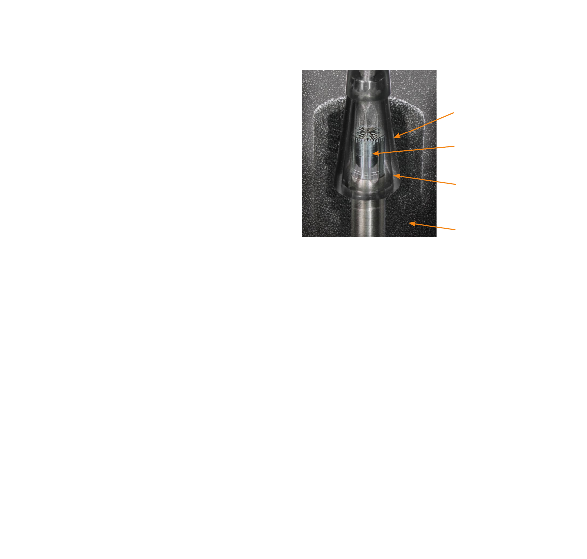
Microphone calibration
The Nor1218 can be calibrated with a sound calibra-
tor for ½” microphones without the need for special
couplers. We recommend using Nor1251 (1000 Hz) or
Nor1253 (250 Hz).
Unscrew the upper part of the Nor1218 to gain
access to the microphone cartridge. Mount the
calibrator slowly and carefully while turning the calibrator
and switch it on. See figure.
If the calibrator frequency is 250 Hz, adjust the
reading to be the level stated for the calibrator, e.g.
124,0 dB for Nor1253 with 124 dB specified level.
If the calibrator frequency is 1000 Hz, adjust the
reading to be 0,1 dB below the stated calibrator level,
e.g. 113,9 dB for Nor1251 calibrator with a stated level
of 114 dB.
This is only valid if the frequency response
correction is turned off. For the Nor131 and Nor139 the
frequency correction is turned off, when entering into
the calibration menu. Perform calibration and calibrate
the microphone as a normal free field microphone. I.E.
-0.1 dB if using a 1000 Hz calibrator. When leaving
the calibration menu, you will observe that the level
measured with the calibrator on, is different from what
obtained in the calibration mode. This is correct, and
is due to the frequency correction added. If horizontal
reference axis is selected, the signal will be about
0.1 dB higher than the calibrated signal, if vertical
reference axis is selected the signal will be 0.3 dB
lower than the calibrated level. This does not apply if
you calibrate with a 250 Hz calibrator since there is no
correction added at this frequency.

5
Norsonic Nor1218
Instruction Manual
Technical description
The outdoor microphone Nor1218 is based on a ½”
working standard microphone type WS2F according
to IEC 61094-4.
Two types of microphones are tested and are recom-
mended; Nor1227 and Nor1228.
Both microphones have a nominal sensitivity of 50
mV/Pa and are self-polarised. However, each micro-
phone is individual calibrated and may differ slightly
from this value.
The upper part of the Nor1218 consists of wind-
screen, rain hood, dust mesh and birdspike and pro-
tects the microphone from rain, snow, dust and insects.
Both the rain hood and the dust mesh are made of a
water-repellent fabric open for the sound. The sound
is reaching the microphone through nine slots placed
equidistantly around the circumference of the circular
body of the upper part. The mechanical part with the
birdspike is also important for the directional response
of the complete microphone system.
The upper part may be removed as one unit and will
thus give easy access to the microphone cartridge for
testing and calibration.The lower part consists of the
base, the microphone cartridge and the preamplifier
Nor1207. A normal IEPE microphone cable supplied
with Norsonic sound level meters, like Nor4531, should
Birdspike
Windscreen
Microphone cartridge
Rain hood
Dust mesh
Preamplifier
Plate for type and
serial number
Base
Unscrew the
upper part
here!
Upper part
6Chapter 4
Technical description
be used for connection to the sound level meter in-
strument. An adaptor for mounting the outdoor micro-
phone on a tripod is included.
The base is made of black polyacetal (POM). The
material is durable and insulating, thus preventing
electric noise from ground loops through the mast.
Drops of water from rain are kept away from the mi-
crophone diaphragm by the combined act of the tubu-
lar windscreen, the rain hood and the dust mesh. The
upper part of the microphone cartridge is air- and wa-
ter tight, and the backside is vented to the air through
the preamplifier.
The Ingress Protection Category for the assembled
microphone is IP55 according to IEC 60529.
Consider the assembly of microphone cartridge
and preamplifier as a single unit when operated in the
field. If disassembled in the field, the performance may
be reduced due to contamination from dust and hu-
midity.
When Nor1218 substitutes a normal measurement
microphone on a sound level meter, a correction of the
frequency response is needed to retain the class of
accuracy for the sound level meter, see Specifications.
Based on the correction, the reference direction may
be selected to be either horizontal or vertical. Horizon-
tal reference direction is usually selected for sound
approaching the microphone mainly along a horizon-
tal axis like noise from industry or vehicles. A vertical
reference axis is usually used for measuring the noise
from aircraft.
The sound level meters Nor131 and Nor139 have
a correction network where the reference axis for the
outdoor microphone Nor1218 may be selected to be
horizontal or vertical.
See separate description in this manual on how to
configure the Nor131 or Nor139, Chapter 5.
Rain hood
Microphone
cartridge
Dust mesh
Wind screen

7
Norsonic Nor1218
Instruction Manual
Frequency response
The typical frequency response for the preamplifier
Nor1207 is shown below. The frequency response for the
outdoor microphone system is therefore mainly deter-
mined by the microphone cartridge and the acoustic
performance of the enclosure.
0.1 1 10 100
Frequency [Hz]
1k 10k 100k
8
7
6
5
4
3
2
1
0
1
2
dB
Typical frequency response for the preamplifier Nor1207. The combination of microphone and preamplifier has an
additional typical attenuation of 6 dB relative to the open circuit sensitivity of the microphone.
8Chapter 4
Technical description
-20.0
-15.0
-10.0
-5.0
0.0
5.0
10.0
15.0
0.4 Hz
0.5 Hz
0.63 Hz
0.8 Hz
1.0 Hz
1.25 Hz
1.6 Hz
2.0 Hz
2.5 Hz
3.15 Hz
4.0 Hz
5.0 Hz
6.3 Hz
8.0 Hz
10 Hz
12.5 Hz
16 Hz
20 Hz
25 Hz
31.5 Hz
40 Hz
50 Hz
63 Hz
80 Hz
100 Hz
125 Hz
160 Hz
200 Hz
250 Hz
315 Hz
400 Hz
500 Hz
630 Hz
800 Hz
1.0 k
1.25 k
1.6 k
2.0 k
2.5 k
3.15 k
4.0 k
5.0 k
6.3 k
8.0 k
10.0 k
12.5 k
16.0 k
20.0 k
A
Z
Self-noise
The electrical noise when the microphone is substi-
tuted by an 20 pF capacitor is shown on the graph be-
low. 0 dB corresponds to 1 µV. For a microphone with
a sensitivity of 50 mV/Pa (Nominal value of Nor1227/
Nor1228), 0 dB voltage also corresponds to the nor-
mal reference pressure for sound: 20 µPa and the
noise level may be compared with sound pressure
level directly.
Typical self-noise of the microphone system when the microphone is substituted by a capacitor with similar capac-
itance as the microphone. Note that the acoustical self-noise for a real microphone will be higher due to thermal
noise in the microphone cartridge.

9
Norsonic Nor1218
Instruction Manual
140
130
120
110
100
90
10 m 50 m 100 m20 m 200 m 500 m
20 kHz
10 kHz
dB
Cable length (100 pF/m)
Level
Cables and cable length
The Nor1218 with its preamplifier Nor1207 has excel-
lent driving capability for long cables. The signal out-
put from the microphone preamplifier will be loaded
by the capacitance of the cable between the micro-
phone system and the instrument. The capacitance
will increase proportionally with the length of the ca-
ble. A typical value for the Nor4531 microphone cable
from Norsonic is 100 pF per metre. Hence, a cable
with length 100 m, will load the output with a capaci-
tance of 10 nF. For lower frequencies there are seldom
problems with long cables. However, when the signal
contains the combination of high amplitude and high
frequency, the capacitive loading will lead to high out-
put current. A limited current capacity will set limits for
the maximum slew-rate for the signal. The figure below
shows the maximum level as function of cable length
and frequency. 20 kHz corresponds to the bandwidth
of the microphone system with the normal microphone
Nor1227 or Nor1228.

10 Chapter 4
Technical description
100 10 k 20 k
1 k
0
1
2
3
4
Frequency [Hz]
+/- 30 deg – Horizontal reference
Directional response
An outdoor microphone system like Nor1218 may
form a part of a sound level meter when applied for
environmental noise monitoring. The combination of
microphone and instrument shall therefore satisfy all
requirements in the international standards for sound
level meters, specified in IEC 61672-1. Ideally, the mi-
crophone shall have the same sensitivity for sound
from any direction. The IEC 61672-1 specifies toler-
ance limits for the directional response.
The directional response of a microphone is the ratio
of the free field response at a particular frequency as
a function of angle of sound incidence to the response
in the reference direction.
The upper adjacent figure shows the directional re-
sponse for Nor1218, when the reference axis is verti-
cal, for the frequencies 1000 Hz, 4000 Hz and 8000
Hz.
IEC 61672-1 specifies tolerance limits for any frequen-
cy. The limits are depending on the angle from the ref-
erence axis and the standard specify tolerance limits
for angles up to ± 30°, up to ± 90° and up to ± 150°
from the reference axis. The lower adjacent figure
shows the typical max. deviation for the sector up to ±
30° from a horizontal reference axis together with the
applicable tolerance limits for a Class 1 sound level
meter.

11
Norsonic Nor1218
Instruction Manual
Frequency response
The figure below shows the typical frequency re-
sponse for sound approaching the microphone in two
directions. The response marked “Vertical” is the re-
sponse for sound approaching the microphone from
above along the bird spikes, when the microphone is
in the recommended vertical direction. The response
marked “Horizontal” is the response for sound ap-
proaching the microphone in a horizontal direction
when the microphone is mounted in the same recom-
mended vertical direction.
Due to the lower sensitivity for higher frequencies, as
shown on the figure, it is recommended to correct the
frequency response to ensure that the response is
within the requirement for Class 1 sound level meters
specified in the international standard IEC 61672-1.
10 10 0 1k 10 k 20 k
30−
25−
20−
15−
10−
5−
0
5
10
Vertical
Horizontal
Sensitivity level [dB]
Frequency [Hz]
When the microphone system is used in connection
with the precision sound level meter Nor131 or Nor139
(for program version 3.0 and above), select 1218 Verti-
cal or Horizontal in the input setup menu to enable the
right settings. If the large windscreen Nor4576 is fit-
ted above the standard windscreen supplied with the
Nor1218 an extra frequency compensation is needed.
This is only possible if the horizontal mode is selected.
Select 2: corrections in the input menu and then 1:
large windscreen in the next submenu to turn this cor-
rection on. Please note that this correction is always
set to OFF each time the instrument is turned off.
There is not possible to use large windscreen if ver-
tical mode is selected. Adding the extra windscreen
is required in some applications when measuring on
wind turbines.

12 Chapter 4
Technical description
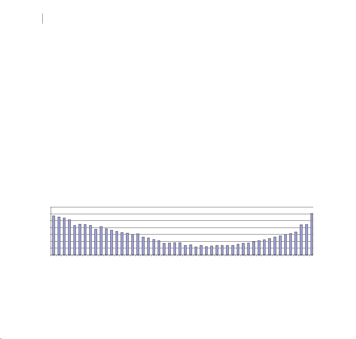
Self-noise and wind
The figure below shows typical self-noise for the mi-
crophone system as levels for the various 1/3-octave
frequency bands re. 20 µPa when the microphone is
placed in a horizontal, laminar flow of air with speed 0,
5 and 10 m/s, respectively. The levels are measured
without frequency compensation. The correspond-
ing A-weighted levels are 16 dB, 40 dB and 48 dB.
Depending on the wind speed, the noise levels are
typically 20 dB to 30 dB lower than for an unprotected
microphone.
0
10
20
30
40
50
60
70
80
90
6,3
8
10
12,5
16
20
25
31,5
40
50
63
80
100
125
160
200
250
315
400
500
630
800
1 k
1.25 k
1.6 k
2 k
2.5 k
3.15 k
4 k
5 k
6.3 k
8.3 k
10 k
12.5 k
16 k
20 k
Sound pressure level [dB]
1/3 octave frequency band [Hz]
0 m/s 5 m/s 10 m/s

13
Norsonic Nor1218
Instruction Manual
Connecting the Nor1218 to
Sound Level Meter Nor131 or
Environmental Noise Meter Nor139
The Nor1218 is designed to be used with the Sound
Level Meter Nor131 or Nor139. These instruments
support all the needed corrections for the two types of
microphones. This chapter discuss how you set up and
use the Sound Level Meter.
In the SETUP – 1 (Instrument menu) – 4 (Input menu),
you select which type transducer you have connected.
Select either “1218 Vertical” for Nor1218 for vertical fre-
quency correction to be applied and “1218 Horizontal”
for horizontal frequency correction.
If the large windscreen Nor4576 is fitted above the
standard windscreen supplied with the Nor1218 an
extra frequency compensation is needed. This is only
possible in the horizontal mode. Select 2: corrections
in the input menu and then 1: large windscreen in the
next submenu to turn this correction on. Please note
that this correction is always set to OFF each time the
instrument is turned off.
It is not possible to use large windscreen if vertical mode
is selected. Adding the extra windscreen is required in
some applications when measuring on wind turbines.

14 Chapter 6
Maintenance
Maintenance
The need for maintenance depends largely on the
environmental conditions where the microphone sys-
tem is used. Contamination of dust, ice or snow on
the windscreen may alter the acoustic performance.
For most applications, it will be sufficient to check the
microphone periodically by using the system check
facility, e.g. every night. For permanent operation we
recommend to inspect the microphone and check the
microphone sensitivity with a calibrator at least two
times a year. The frequency for checking may be in-
creased in places with difficult weather conditions or
excess of dust.
The windscreen consists of two parts. The outer
part is hollow and sealed by a lower ring-shaped part.
Remove the upper part of the windscreen with care
(see figure). When the upper part is lifted upward, en-
sure that the lower part stay fixed – otherwise the rain
hood above may be harmed.
The outer part of the windscreen may be cleaned
by washing by hand using standard household wash-
ing up detergents. Ensure that it has been thoroughly
rinsed in clean water and is completely dry before it is
remounted. Do not use excessive heat for the drying:
85ºC maximum. However, we recommend to replace
the whole upper part every second year. In some loca-
tions, near to chemical complexes or in coastal instal-
lations it may be necessary to replace the windscreen
earlier (spare part Nor4529).
The lower part of the windscreen, the dust mesh
and rain hood are not parts that can be serviced by
the user. In case of wear or strong contamination we
recommend to order a replacement unit (Spare part
Nor4560) or send the part to the factory for refurbish-
ment.
Do not disassemble the assembly of microphone
and preamplifier outdoors. Contamination from humid-
ity or dust – or from your finger sweat – may lower the
performance.
Table of contents
Other Norsonic Microphone manuals


