Northern Industrial Tools 1981202 User manual

AirTools
Made in China
Read carefully and understandRULES FOR SAFEOPERATION and instructions
before operating. Failureto follow thesafety rules andother basic safety
precautions may resultin serious personal injury.
ITEM#1981202
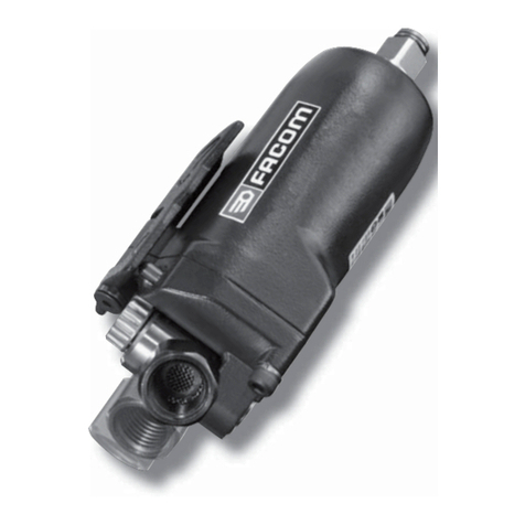
1/2"BLACKNICKELAIRIMPACTWRENCH
USER'SMANUAL

For technicalquestions and replacementparts, pleasecall 1-800-222-5381.
Thankyouvery much for choosinga NORTHERNTOOL+ EQUIPMENTCO., Product!
For future reference, pleasecomplete theowner'srecordbelow:
Model: _______________ Purchase Date:_______________
Savethe receipt, warranty andthese instructions. It isimportant that you read the
entireinstruction sheet to become familiarwith this productbeforeyoubegin using it.
This productis designedforcertain applications only.Northern Tool+ Equipment
stronglyrecommends that thisproduct isnot modifiedand/orusedforany
application other than thatforwhich it was designed. If you have any questionsrelative
to aparticular application, DONOTuse the product until you havefirst contacted
Northern Tool+ Equipmentto determine ifit canor should be performedon theproduct.
Beforeusingthis product,please read the followinginstructions carefully.
TechnicalSpecifications
PersonalSafety
1. Stay alert.Watchwhatyouare doing, and use common sensewhen operating a
pneumatic tool. Do notuse apneumatic tool whiletired or under theinfluence of
drugs,alcohol,or medication.A momentof inattentionwhileoperating pneumatic
toolsmayresultin serious personal injury.
2. Dress properly. Donot wear loose clothingor jewelry.Containlong hair.Keepyour
hair, clothing,and glovesawayfrommovingparts. Looseclothes,jewelry, orlong
haircan be caught inmovingparts.
SAVETHISMANUAL
Youwill need this manual for thesafetywarnings andprecautions, assembly, operating,
inspection, maintenance and cleaning procedures, parts listand assemblydiagram.
Keepthis manualand invoicein asafeand dry placeforfuturereference.
GENERALSAFETYRULES
Readand understand allinstructions.
Failureto followall instructions listed inthe followingpagesmayresultin electric shock,
fire, and/or seriousinjury.
WorkArea
1. Keep your work area clean and well lit.Cluttered benches and dark areas invite
accidents.
2. Donot operatepneumatic tools inexplosive atmospheres, such asin thepresence
of flammableliquids,gases,or dust. Pneumatic toolscreatesparkswhichmayignite
flammables.
3. Keep bystanders, children, pets and onlookersawaywhile operating apneumatic tool.
Distractionscan causeyou to losecontrol. Protectothers in theworkareafromdebris
suchas metal filings andsparks. Provide barriers orshieldsas needed.
Item
Square Drive
Free Speed
Max. Torque
Air Consumption
Air Inlet Diameter
Min. Hose Size
Max. air pressure
Description
1/2"
7500 RPM
230 ft-lbs
4 CFM
1/4"- 18NPT
3/8"
90 PSI
Description
Item
1 of 5

3. Avoidaccidental starting. Be surethe trigger isoff before connectingto the air
supply. Carrying pneumatictools with your finger onthe trigger,or connecting
pneumatic tools to the airsupply with theTrigger on,invites accidents.
4. Removeadjusting keysor wrenches beforeturning on thetool. A wrenchor a key
that is left attachedto a rotating part of thetool mayresult in personalinjury.
5. Do notoverreach. Keepproper footingand balance atall times. Properfooting
and balance enablesbetter controlof the toolin unexpectedsituations.
6. Use safety equipment. Always wear ANSI-approved safetyglasses underneath a
full face shield,and hearing protection.
UseandCare
1. Use clampsor other practicalways tosecure and support thework piece to a stable
platform. Holding thework byhand is unstableand may leadto loss ofcontrol. Only
work on aworkpiece that isproperly secured.
2. Do notforce thetool. Use thecorrect tool for your application.The correct toolwill
do the jobbetter and safer at therate forwhich it isdesigned.
3. Do notuse the power tool ifthe trigger doesnot turn iton or off.Any toolthat cannot
be controlled withthe Triggeris dangerous andmust be replaced.
4. Disconnect theair hose fromthe tool before making anyadjustments, changing
accessories, or storingthe tool. Suchpreventive safety measures reducethe risk
of starting the tool accidentally.
5. Store idletools out ofreach of childrenand other untrainedpersons. Toolsare
dangerous in thehands of untrainedusers.
6. Maintain toolswith care. Donot use adamaged tool. Tag damaged tools Do not use
until repaired.
7.Check for misalignmentor binding ofmoving parts, breakagesof parts, damaged air
hose (not included),and any other condition thatmay affect thetool's operation. If
damaged, havethe tool servicedbefore using. Many accidents arecaused by poorly
maintained tools.
8. Use onlyaccessories that arerecommended by themanufacturer foryour model.
Accessories that may be suitablefor one tool may becomehazardous when usedon
another tool.
Service
1. Toolservice must be performedonly by qualifiedrepair personnel. Service or
maintenance performed byunqualified personnel couldresult in arisk of injury.
2. When servicing atool, use onlyidentical replacement parts. Follow instructions in
the Inspection, Maintenanceand Cleaning sectionof this manual.Use of
unauthorized parts or failure to follow maintenanceinstructions may create a risk
of injury.
SPECIFICSAFETYRULES
1. Toavoid accidentalinjury, alwayswear ANSI-approvedsafety glasses,a full face
shield, and hearingprotection whenoperating the tool.
2. Use clean,dry, regulated,compressed air at90 PSI. Donot exceedthe
recommended 90 PSI.Never useoxygen, carbon dioxide, combustible gases,or
any otherbottled gas asa power source for thistool.
3. When connectingto the airsupply: Prior toeach use, ifan automatic oileris not
used, add twodrops of airtool oil (notincluded) into theair inlet fittingof the tool.
4. Alwaysdisconnect the toolfrom its compressed air supplysource, and squeeze the
Trigger to release allcompressed air inthe tool before performing anymaintenance
or service.
""
2 of 5

5. The warnings,precautions, and instructionsdiscussed in thismanual can notcover
all possible conditionsand situations thatmay occur. The operatormust understand
that common senseand caution arefactors which cannotbe built intothis product,
but must besupplied by theoperator.
ASSEMBLYANDOPERATINGINSTRUCTIONS
To attach a quick connector
Prior to performingany assembly and/oradjustment procedures, make sure theair
supply hose (notincluded) is disconnectedfrom the impact wrench.
1.Prior touse, the impactwrench requires theattachment of aquick-connector into
its air inlet.To doso, wrap approximately 3" ofpipe thread sealertape (not included)
around the malethreads of aquick-connector.Then, firmly tightenthe
quick-connector intothe air inlet.
Loosening
1.Attach thecorrect size socketto the anvil.
2.Set thecompressor's pressure regulatorto 90 PSI.Do not setthe compressor's
outlet regulator above90PSI.
3.Connect thetool to theair compressor's hose.If leakage isdetected, disconnect
the air hoseand fix itcorrect before use.
4.Place thesocket over thenut to loosen.
5.Grip thetool firmly. Press theREVERSE valve infrom the areaabove the trigger
so that theREVERSE valve protrudesout the backof the housing.Press the trigger
to start thetool.
Caution:
Make sure thenut or boltcan withstand theimpact wrench's workingtorque.
NOTE:
ØIf the toolcannot loosen thenut, DO NOTraise the outletpressure of theair
compressor.
ØWhen the nutis moved, stopthe tool byreleasing the triggerand remove thetool
from the nut.Remove the nutfrom the socketif needed.
Tightening
The working torqueof the impactwrench is 230ft.-lbs. Make surethat the
nut or boltyou are usingthe tool totighten can withstandthe rated torque.
1.Tightenthe nut asfar as youcan by hand.
2.Place thesocket on thenut. Press theREVERSE valve forwardso it protrudes
out the frontof the Housing.Press the triggerto start thetool.
WARNING
!
Fig. 1
3 of 5

NOTE:
ØIf the toolstalls while tightening,DO NOTraise the outletpressure of theair
compressor above 90PSI.
ØWhen the nuthas been tightened,remove the tooland socket.
Do not over-tighten.
ØIf available, checkthe recommended torquespecifications for thenut.
Youshould use atorque wrench totorque the nutafter using theimpact wrench.
INSPECTION,MAINTENANCEANDCLEANING
1. Alwaysmake sure thetrigger is inits OFF position, and disconnectthe tool from
its compressed airsupply before performingany inspection, adjustments,
maintenance, or cleaning.
2. Before eachuse, inspect thegeneral condition ofthe tool. Checkfor loose screws,
misalignment or bindingof moving parts,cracked or broken parts, damagedair hose,
and any othercondition that mayaffect its safeoperation. If abnormalnoise or
vibration occurs, have the problemcorrected beforefurther use. Do notuse
damaged equipment.
3. Daily: Witha clean cloth,remove alldirt, oil, and greasefrom the tool. If necessary,
you mayuse a milddetergent. Do notuse solvents, asdamaged to thetool mayoccur.
Do not immersethe tool inany liquids.
GENERALTOUBLESHOOTING
TROUBLES
ØTool doesnot run ata normal speedor at avariable speed.
ØThe motor blocks.
ØAutomatic start whenconnected tocompressed air.
ØTorquereduces
ØAbnormal vibrating Easyhot rising atthe housing.
CAUSES
ØAir supply isnot enough (airpressure not ina required standard)
ØSpeed controller/switch breaksdown
ØRotor bladesbreak or wearout
ØDust gets intothe motor
ØThrottle leveror starting trigger malfunctions
ØAir leakage atthe inlet orsomewhere else
ØBearing damages
ØCorrespondent O-rings wearout or outof position
ØLack of lubricating
TROUBLESHOOTING
ØCheck the airhose to seewhether it isblocked or twisted for lessair supply
ØCheck the aircompressor to gainthe correct airpressure required
ØReplace rotorblades
ØDisassemble the tooland clean theinner structure underproper instructions
ØCheck and fixthe throttle lever or startingtrigger for accurate operation
ØCheck the airleakage and fixit under properinstruction
ØReplace newbearing
ØReplace the damagedO-ring or putit back incorrect position
ØOil/Lubricate the tool consistently untilit gains theright speed andtorque.
NOTE: For anyother special troubleswhich cannot besettled down by the operator,
please contact theselling agent fromwhom you purchasedthe tool.
""
4 of 5
Table of contents
Other Northern Industrial Tools Impact Driver manuals
