Novar EP/2-EA User manual

Ethernet®Adapter
Installation Instructions
DOC. #569040000—A 7/30/04 PRINTED IN U.S.A.

Disclaimer
Logic One®is a registered trademark of Novar Controls Corporation.
The material in this manual is for information purposes only. The contents and the product it
describes are subject to change without notice. Novar Controls Corporation makes no
representations or warranties with respect to this manual.
In no event shall Novar Controls Corporation be liable for technical or editorial omissions or mistakes
in this manual, nor shall it be liable for any damages, direct or incidental, arising out of or related to
the use of this manual.
Copyright © 2004 by Novar Controls Corporation. All rights reserved.
No part of this manual may be reproduced in any form or by any means
without prior written permission from Novar Controls Corporation.
Novar Controls Corporation
6060 Rockside Woods Blvd., Cleveland, OH 44131
Tel: 800.348.1235 www.novarcontrols.com

Description
The Ethernet®Adapter module (Model EP/2-EA) is connected to Novar
Controls’ Executive Processor 2 (EP/2) to allow the EP/2 to communicate over a
Local Area Network (LAN) that uses Ethernet hardware and software. The
Ethernet network provides the capability for multiple EP/2s, Novar Controls
workstations, and other devices to communicate with each other across the
network. By communicating with an EP/2 through Ethernet, any properly
configured personal computer can access real-time, online data from the Logic
One®system.
The EP/2 requires a PROM level of 18.20 or greater and a download version of
18.20 or greater to use the Ethernet Adapter.
Specifications
Operating Environment
Temperature: 32° to 140°F (0° to 60°C)
Humidity: 0 to 95% Relative, noncondensing
Physical Dimensions
Height: 7 inches
Width: 3.63 inches
Depth: 1 inch
Weight: 8 oz (All aluminum enclosure)
Precautions
Observe all national and local electrical codes during installation.
Mounting the Ethernet
Adapter
CAUTION! Remove the EP/2 electronics assembly before
mounting the Ethernet Adapter to the EP/2 baseplate.
The following items are needed for installation:
§Ethernet Adapter
§Three 1-inch screws (included with the adapter’s hardware kit)
§A twisted-pair, Ethernet-compatible cable (10Base-T) with an RJ-45 connector.
The adapter should be mounted inside the EP/2 baseplate enclosure, to the left of
the EP/2’s transition board (see Figure 1).
NOTE! Complete the installation procedures in the order they are
presented in these instructions. Varying from these
instructions could result in damage to the Ethernet Adapter
and/or the EP/2.
Doc. #569040000—A 7/30/04 1
Ethernet®Adapter Installation Instructions

NOTE! The knockout hole on the left side of the EP/2 baseplate
will be blocked by the Ethernet Adapter. If wires run
through this hole, they must be rerouted. Do not route
them under the adapter. The Ethernet Adapter must sit
firmly against the baseplate to ensure a proper connection.
Use the following procedure to mount the Ethernet Adapter to the baseplate of
the EP/2.
Step Procedure
1 Use the hex wrench that came with the hardware kit to loosen
the two screws at the bottom of the EP/2 baseplate and lift off the
cover.
2 Loosen the retaining screws in the two mounting posts on which
the EP/2 electronics assembly sits.
§Completely remove the screw from the left mounting post (as
indicated in Figure 1).
NOTE! The Ethernet Adapter and the EP/2 electronics
assembly will not connect properly unless the left
mounting post screw is removed and the adapter is
installed before the electronics assembly is
returned to the EP/2 baseplate.
3 Slide the EP/2 electronics assembly up and away from the lip at
the top of the baseplate and set it aside.
continued
2Doc. #569040000—A 7/30/04
Ethernet®Adapter Installation Instructions
1
20
19
37
EXECUTIVE PROCESSOR 2
24V,1A
RS-232 PORT
CLASS2, 5V MAX CIRCUITS
RS-485COMMUNICATION NETWORKS
LAN
'B'M ODULE
DIRECTION DIRECTION
'A'MODULE
SHIELD SHIELD SHIELD
28
27
26
25
24
23
22
21
20
19
18
17
16
15
INPUT
SENSOR
INPUT
SENSOR
OUTDOORLIGHT
OUTDOORTEMP
PULSE
DEMAND
LOSS
PHASE
POWERINPUT
STATUS
1
2
3
4
5
6
7
8
9
10
11
12
13
14
30VA
CLASS2
CLASS2
INPUTINPUTINPUT
TELEPHONELINE
TRANSITION BOARD
NOVARCONTROLS CORPORATION
EMERGENCY
OUTPUTX
24VAC
WARNING
DONOT PLUG THISMODULE INTO A
POWEREDCONTROLLER!
10BASE-TLAN
CONNECTION
MOUNTCONTROLLER BASEPLATEAND SLIDE
CONTROLLERELECTRONICSINTO PLACE.
RECEIVE
TRANSMIT
POLARITY
COLLISION
GOODLINK
ETHERNET Adapter
MODEL EP/2 - EA
®
++
Remove this screw before
mounting the Ethernet Adapter
EP/2 Baseplate with
Electronics removed
Position the Ethernet
Adapter over these
mounting posts and
align the holes so the
screws can be inserted
Ethernet address
(M.A.C. identification)
Insert the Ethernet network
cable here
Figure 1. Ethernet Adapter Module Installation
Step Procedure
4 Align the adapter’s three mounting holes with the three mounting
posts (shown in Figure 1) and carefully push the adapter toward
the baseplate.
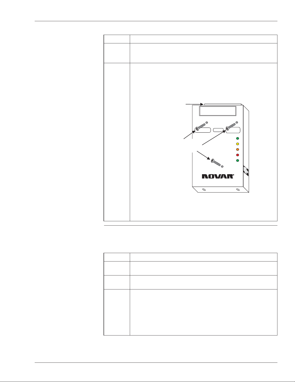
5 Insert the three 1-inch screws included with the mounting kit (see
Figure 2), making certain that they are aligned correctly, and
tighten (using a Phillips screwdriver) to ensure the adapter is
mounted securely.
Making Connections to
the Ethernet Adapter
Use the following procedure to connect the Ethernet Adapter to the EP/2.
Step Procedure
1 Insert the RJ-45 connector from the Ethernet network cable into
the port on the right side of the Ethernet Adapter (see Figure 1).
2 Slide the EP/2 electronics assembly over the lip at the top of the
baseplate and down over the mounting posts.
3 Locate the DB-37 connector on the top of the adapter, carefully
align the pins, and guide the DB-37 connectors on the EP/2
electronics assembly over the connector on the Ethernet Adapter
and over the connector on the transition board of the EP/2.
§Do not force the connection.
continued
Doc. #569040000—A 7/30/04 3
Ethernet®Adapter Installation Instructions
WARNING
DO NOT PLUG THIS MODULE INTO A
POWERED CONTROLLER!
10BASE-T LAN
CONNECTION
MOUNT CONTROLLER BASEPLATE AND SLIDE
CONTROLLER ELECTRONICS INTO PLACE.
RECEIVE
TRANSMIT
POLARITY
COLLISION
GOOD LINK
ETHERNET Adapter
MODEL EP/2 - EA
®
++
Insert three screws here
to mount the Ethernet
Adapter to the EP/2
DB-37 connector
for connecting
to the EP/2
Electronics
Figure 2. Mounting screw locations on the
Ethernet Adapter

Step Procedure
4 Use the hex wrench to tighten the retaining screw in the
mounting post on the right side to secure the EP/2 electronics
assembly to the baseplate.
§The left retaining screw cannot be used with the Ethernet
Adapter installed.
Checking Installation
To check the installation, monitor the five status light-emitting diodes (LEDs) on
the face of the Ethernet Adapter.
§The Good Link status LED will blink once when power is supplied to the
EP/2. After several seconds it will remain lit, indicating that the network is
correctly wired and configured and working properly.
§The Polarity status LED, when lit, indicates that the network wiring polarity is
reversed. The adapter will continue to function. Check the Ethernet network
cable wiring and correct the polarity.
§The Receive and Transmit status LEDs flash on and off intermittently to show
that communication is occurring if the EP/2 is communicating with the LAN.
§The Collision status LED blinks occasionally during normal communications.
If this LED blinks often or stays on for long periods it indicates a problem.
Monitor the Ethernet network’s operation on the EP/2’s display. Refer to Novar’s
Controls EP/2 Keypad and Display Instructions (Document No. 5601190).
LOGIC ONE®IS A REGISTERED TRADEMARK OF NOVAR CONTROLS CORPORATION.
ETHERNET®IS A REGISTERED TRADEMARK OF XEROX CORPORATION.
THE CONTENTS OF THIS DOCUMENT ARE SUBJECT TO CHANGE WITHOUT NOTICE.
COPYRIGHT © 2004 BY NOVAR CONTROLS CORPORATION. ALL RIGHTS RESERVED.
PRINTED IN THE U.S.A.
NOVAR CONTROLS CORPORATION
6060 ROCKSIDE WOODS BLVD., CLEVELAND, OH 44131
TEL.: 800.348.1235 WWW.NOVARCONTROLS.COM
4Doc. #569040000—A 7/30/04
Ethernet®Adapter Installation Instructions
Table of contents


