The OUT (MAIN) output
This produces a signal that is equivalent to the sum o the our inputs as controlled by the our
level control pots. As with all mixer circuits it is possible to exceed the maximum allowed
output voltage i the input signals and input levels are set too high. For example using three
input signals o 6V peak with their pots set to ull should produce a theoretical 18V peak
signal. This is beyond the capabilities o the Fourmix since the power supply to the module is
only +/-15V and the circuitry can produce at best a +/-13V signal rom the output. This
discrepancy causes what is called 'clipping'. It is called this because the output wave orm is
essentially clipped o at the top and bottom where it wants to go but cannot. This hard
clipping tends to sound harsh and overly bright. It can be musically interesting though and
doesn't actually cause any harm to the module.
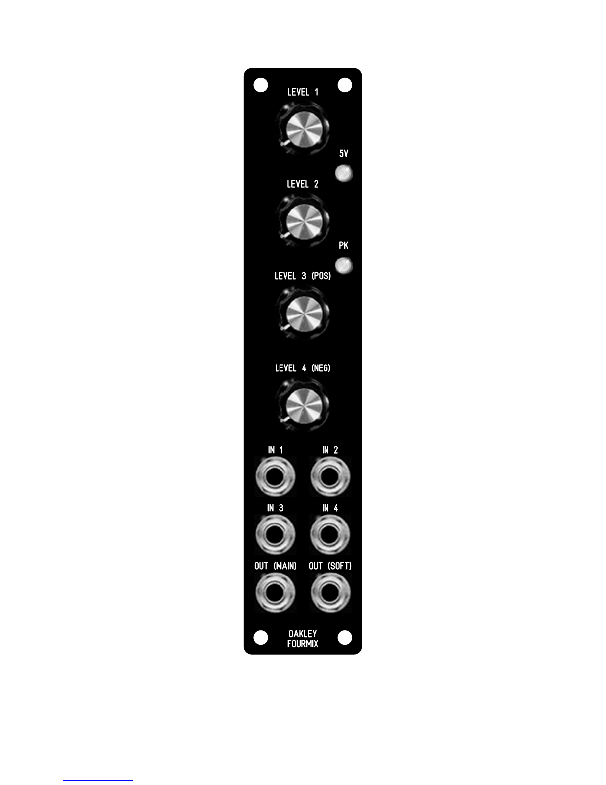
The two LEDs on the ront panel help you avoid hard clipping. I the red peak LED is coming
on o ten then it is more than likely that you are hard clipping the MAIN (OUT) signal. I you
want to avoid such clipping you should be looking at never allowing the peak LED to light up
at all. The green LED indicates a signal above +/-5V and this is the normal signal level
expected within a modular synthesiser. Typically, the input pots should be adjusted so that the
green LED should be coming on occasionally.
The OUT (MAIN) output signal is bu ered. That is it will not droop signi icantly with
increased load. In other words, unlike the normal outputs o audio modules, the output level
will not change no matter how many modules (within reason) you connect up to it. Thus it is
use ul or distributing sensitive control voltages to multiples o modules. It should be noted
that any Oakley modules that process KeyCV (the main pitch controlling control voltage in the
modular) will also eature the same bu ered output circuitry as the Fourmix.
The main output o the Fourmix can be used as a precision voltage source. Channel 3 and
Channel 4 produce positive and negative re erence voltages respectively when no jack plug is
inserted into their input socket. With their level pots set to their maximum the voltage is just
under +4.5V or channel 3 only and just under -4.5V or channel 4 only. Since each channel is
o opposing polarity using both channels simultaneously will produce a cancellation e ect.
That is, i both 3 and 4 are set to their maximum settings the inal output voltage will
completely cancel and produce zero volts rom the output.
5