OceanAudio The Ark 500 Series User manual

The Ark
Owner’s Manual
www.oceanaudio.co.uk
Ark 516 Expander
Ark 508 Expander
Ark 504
Ark 516

Ark 500 range - Owner’s Manual - Revision 2.2 - page 2
Contents
1. Introduction ............................................................................................................. 3
2. Features .................................................................................................................. 4
3. Quick start ............................................................................................................... 5
!3.1!Power Connections .................................................................................... 6
!3.2!Audio Connections ..................................................................................... 7
!3.3!Connecting without patchbay and without modules installed...................... 7
!3.4!Connecting without patchbay but with modules installed ........................... 8
!3.5!Using the console with a patchbay ............................................................. 9
4. Audio Connections - Wiring D-Sub connectors ......................................................10
!4.1!Standard D-Sub pin connection ................................................................ 11
!4.2!Master Insert Sends, Returns & Master Outputs D-Sub pin connections . 12
!4.3!Control Room, Alt Mon & Studio Playback D-Sub pin connections .......... 13
!4.4!2-Track Returns D-Sub pin connections ................................................... 14
!4.5!Auxiliary Sends D-Sub pin connections .................................................... 15
5. The Ark input module ............................................................................................. 16
6. The Ark submaster module (Ark 504 and 516 only)................................................ 20
7. The Ark master module (Ark 504 and 516 only)...................................................... 24
8. More on metering ................................................................................................... 28
9. More on levels when using Digital Audio Interfaces ............................................... 29
10. More on speakers ................................................................................................... 30
11. More on grounding .................................................................................................. 31
12. Technical Specifications .......................................................................................... 32

Ark 500 range - Owner’s Manual - Revision 2.2 - page 3
Introduction
Thank you for your purchase of the Ark.
This manual is for all models of the Ark 500 range
(Ark 504, Ark 516, Ark 508 Expander and Ark 516 Expander)
We hope you’ll have as much pleasure using it as we had designing and building it.
The Ark is designed by Malcolm Toft, who was the founder of console manufacturer Trident Audio
Developments in 1972. Prior to that he was a recording engineer whose credits include the David Bowie
‘Space Oddity’ album, three albums with T-Rex and James Taylor’s first album. He was also involved
with the mixing of the Beatles ‘Hey Jude’ single at Trident Recording Studios in 1968.
Malcolm has been designing recording consoles for over forty years and some of the artists who have
recorded hits on his consoles include: Stevie Wonder, Herbie Hancock, Rod Stewart, Queen, David
Bowie and Elton John. More recently, Radiohead, Muse, Dire Straits, Coldplay and Oasis have added
their name to the list. And now you !!
Malcolm was made a visiting professor by Leeds College of music in 2008 in recognition of his unique
combination of experience as a recording engineer and console designer. It is this wealth of experience
and pedigree that is brought to the design of the Ark consoles.
Enjoy working with the Ark
All the best
and the Ocean Audio team
Here are just a few artists, studios and bands whose names may sound familiar to you, and who have
used, or are still using, consoles designed by Malcolm Toft.
Elton John - David Bowie - Queen - Lou Reed - Harry Nilsson - James Taylor - Carly Simon
The Eagles - The Beatles - T-Rex - Dire Straits - Bachman Turner Overdrive - Linda Rondstat
Supertramp - Thin Lizzy - George Harrison - Jeff Beck - Radiohead - Tony Visconti
Ringo Star - Paul McCartney - Brian Eno - Supertramp - Chris De Burgh - Ian Anderson
Amy Winehouse - The Manic Street Preachers - Ricky Nelson - Paul Weller - Oasis - Muse
The Chemical Brothers - Hard-Fi - The Nice - Rick Wakeman - Joe Cocker - The Move
Aphrodite’s Child - Blood Sweat and Tears - The Nice - Phil Manzanera - The Record Plant LA
The Record Plant San Francisco - Chipping Norton Studios - Sarm Recording Studios
Trident Studios - Liverpool Institute of Performing Arts - Leeds College of Music - Sound 80 Minneapolis
Armin van Buuren - Lenny Kravitz - Dennis Ferrer - Vienna University of Performing Arts - Frank Sinatra
- Genesis - Cherokee Studios Hollywood

Ark 500 range - Owner’s Manual - Revision 2.2 - page 4
Features
The Ark is designed to be as flexible as possible. While it can be used as a traditional analogue console (just insert
a Mic Pre and an EQ per channel), we would like to encourage you to explore all possibilities and use this console
to really suit your workflow.
The Ark has been designed to fully support the 500 series module system.
- The Ark 504 provides slots and power for up to 16 of these modules.
- The Ark 516 provides slots and power for up to 40 of these modules.
- The Ark 508 expander adds another 16 slots.
- The Ark 516 expander adds another 32 slots.
Each input of each console accommodates two 500 series modules physically placed above them.
The sub-master section of the Ark 504 and 516 provides for up to eight 500 series Modules.
The Ark provides all the infrastructure needed to make an extremely versatile recording console using any
combination of 500 series mic pre-amplifiers, equalisers, compressors, effects, etc. available from a long list of
manufacturers. This means that the console can in fact inherit the particular sound of any third party 500 series
module you want to use.
The Ark consoles and expanders can be combined in any way you want.
Two expanders (either 508 or 516) can be connected to each of the 504 and 516 master consoles.
This gives you a huge number of 500 series slots and possibilities.
Ark 504
Ark 516
Ark 508 Ex
Ark 516 Ex
Slots for 500 Series modules
Combined with Ark 504
Combined with Ark 516
Combined with Ark 508 Ex
Combined with Ark 516 Ex
Combined with two Ark 508 Ex
Combined with one Ark 508 Ex and one Ark 516 Ex
Combined with two Ark 516 Ex
16
40
16
32
-
-
32
48
-
-
56
72
32
56
-
-
48
72
-
-
48
72
-
-
64
88
-
-
80
104
-
-
The easiest way to implement use of 500 series modules in the Ark signal chain is to insert mic pre-amplifiers into
the top row of slots and connect the outputs of these to the ‘Channel External Inputs’.
500 series equalisers can be inserted into the lower row of slots and the inputs and outputs to these could be made
via the ‘Channel Insert Sends and Returns’. This will turn the Ark in a traditional analogue console.
Alternatively, and by using a patch bay, any chain of 500 series modules can be used on any of the inputs, outputs
or inserts of the Ark. This gives you complete flexibility to create the sound you’re after.
The console electronics have deliberately been designed to be as transparent and with as much headroom as
possible. The Ark can be used without the addition of any 500 series modules as a stand alone line level console.
In a multi-track studio environment the console will perform both tracking and remix functions equally well. All
inputs and outputs are electronically balanced and ground sensing outputs are used to make sure that interfacing
to external equipment is never compromised.

Ark 500 range - Owner’s Manual - Revision 2.2 - page 5
Because of the channel monitor and direct output facilities, recording instruments to a DAW or tape is simple and of
very high quality. When mixing down, there is a large number of inputs to the stereo buss available.
Here’s an overview which shows you the number of inputs for any combination of Ark models :
Ark 504
Ark 516
Ark 508 Ex
Ark 516 Ex
Total inputs to mix bus
Combined with Ark 504
Combined with Ark 516
Combined with Ark 508 Ex
Combined with Ark 516 Ex
Combined with two Ark 508 Ex
Combined with one Ark 508 Ex and one Ark 516 Ex
Combined with two Ark 516 Ex
24
48
16
32
-
-
40
56
-
-
64
80
40
64
-
-
56
80
-
-
56
80
-
-
72
96
-
-
88
112
-
-
The console has also been designed with ease of servicing in mind.
Its fully modular construction makes it a simple matter to remove any module should a component need replacing.
All active circuitry (IC's etc) are socketed, again to aid servicing. All passive components (resistors, capacitors
etc.) are of conventional types and are not surface mount (because surface mount components are difficult to
remove and replace). The modules connect to each other via motherboards, which ensure maximum reliability
and freedom from wiring errors.
Construction of the frame itself is a combination of aluminium and steel to ensure that the console is rigid yet as
light as possible.
Connections to the console are via Tascam standard 25 way D-Sub connectors. This allows for easy connection to
a patchbay which greatly increases the flexibility of the system.
The metering system accommodates either recording directly from the channel direct outputs or via the separate
sub group section.
By carefully following the installation procedures detailed in the following pages, your Ark console will give you
years of professional audio quality and reliable service.

Ark 500 range - Owner’s Manual - Revision 2.2 - page 6
Quick Start
3.1 Power Connections
The Ark 504, Ark 516 and Ark 516 Expander are supplied with a high quality power supply.
The power supply of the Ark 504 has enough power for one additional Ark 508 expander.
The Ark 508 Expander needs it’s own power supply when used with the Ark 516.
Make sure to use an earthed cable when connecting the AC power source to the 3-pin euro socket at the
back of the power supply.
The supply uses the latest ‘switch mode’ power techniques which negate the need for heavy and
inefficient power transformers. They are also extremely efficient which means that despite their high
current load capacity, they do not run hot. As a consequence cooling fans are not required and therefore
the power supply is completely silent in operation. As they still generate a small amount of heat it is
however always good practice to make sure that they operate in a well ventilated area, preferably with at
least 1U rack space between the supply and other equipment.
Another advantage of switch mode power supplies is that they will operate on a wide
AC input voltage range (100v to 260v AC). Consequently they can be operated virtually anywhere in the
world without the need for adjustment.
The supplies are provided with short-circuit and over-voltage protection.
Low voltage DC is supplied to the console via a circular locking connector.
- Push the connector firmly into the mating socket on the rear of the console.
- Use the locking ring to make sure that the cable cannot be accidentally pulled from the console.
- Make sure you make all connections before switching on the power supply.
The DC power connections are as follows:
Pin 1 Ground
Pin 2 +16V
Pin 3 -16V
Pin 4 +8V
Pin 5 +48V
The power supply is fitted with four red LED's which indicate that the +16, -16, +8V and +48 voltages
are functioning. If for any reason any of the LED's fail to illuminate, do not operate the console. Turn
the power supply off immediately and check that the appropriate front panel fuse(s) are not blown. If
any fuse has blown, replace with one of the same rating and try again. If the fuse has not blown or a
replacement fails subsequently, seek qualified help.

Ark 500 range - Owner’s Manual - Revision 2.2 - page 7
3.2 Audio Connections
So as to provide complete flexibility and provide greater access to the many inputs and outputs
available, the Ark uses the Tascam standard 25 way D-Sub connector system.
Because of this, when used without a patchbay certain functions in the console will not work unless they
are ‘normalled, through.
These functions are (as marked on the rear panel):
‘Channel Insert Sends 1-8’ to ‘Channel Insert Returns 1-8’,
‘Channel Insert Sends 9-16’ to ‘Channel Insert Returns 9-16’ (on the Ark 516 and 516 expander)
‘Group Insert Sends 1-8’ to ‘Group Insert Returns 1-8’ (on the Ark 504 and 516)
‘Mas Ins Send/Ret’ (on the Ark 504 and 516)
3.3 Connections without patchbay and without any modules installed
To use the Ark without any modules installed, you need to make a couple of connections to enable
continuity of signal through the console:
- Connect ‘Channel Insert Sends 1-8’ to ‘Channel Insert Returns 1-8’
- Connect ‘Channel Insert Sends 9-16’ to ‘Channel Insert Returns 9-16’ (the Ark 516 and 516 expander)
- Connect ‘Group Insert Sends 1-8’ to ‘Group Insert Returns 1-8’ (the Ark 504 and 516 only)
These are in the same vertical rows so only short male to male 25 way D-Sub cables are needed.
- Connect the supplied factory assembled plug to the 'Mas Ins Send/Ret' connector (the Ark 504 and 516
only).
As the ‘Mas Ins Send/Ret’ linking is slightly more complicated due to the fact that the D-Sub connector
on which these functions are located also provides the Master left/right outputs, a factory assembled
plug is provided as a ‘get you started’ facility. This plug is located within the power supply packaging.

Ark 500 range - Owner’s Manual - Revision 2.2 - page 8
3.4 Connections without patchbay but with modules installed
For this example we’ll install 16x Mic Pres in the Top Rack slots of the Ark 516, 16x EQs in the Lower
Rack slots and 8x compressors in the Monitor Rack slots.
We need to make sure that we once again enable continuity of signal through the console.
The connections are a bit different now.
- Connect ‘Top Rack Outputs 1-8’ to ‘Channel Ext I/P 1-8’
- Connect ‘Channel Insert Sends 1-8’ to ‘Lower Rack Inputs 1-8’
- Connect ‘Lower Rack Outputs 1-8’ to ‘Channel Insert Returns 1-8’
- Do the same for channels 9-16
- Connect ‘Group Insert Sends’ to ‘Monitor Rack Inputs’
- Connect ‘Monitor Rack Outputs’ to ‘Group Insert Returns’
- Connect the supplied factory assembled plug to the 'Mas Ins Send/Ret' connector.
As the ‘Mas Ins Send/Ret’ linking is slightly more complicated due to the fact that the D-Sub connector
on which these functions are located also provides the Master left/right outputs, a factory assembled
plug is provided as a ‘get you started’ facility. This plug is located within the power supply packaging.
In this example, connect your microphones to the Top Rack Inputs.
The outputs of the Mic Pres will go to the Channel External Inputs.
You’ll of course need to select Ext Input on every channel to get signal from your Mic Pres.
The input and output of the EQs are on the insert point of each channel.
This allows you to also use the EQs if you switch to the Line input.
In our example, we also inserted compressors in the Monitor Racks, and connected these to the group
inserts.
By routing the input channels to the group(s) we can use a compressor on any input channel or
combination of channels.
This way, we can also use parallel compression, if we want.
Remember that the group output (after the insert return) is send to the master L/R bus if the Replay
switch on the lower section of the submaster module is depressed (out).
Please check the section on The Ark subgroup module for details.

Ark 500 range - Owner’s Manual - Revision 2.2 - page 9
3.5 Using the console with a patchbay
The previous examples showed basic ways to use the Ark.
But the Ark offers much more. And as with so many things in audio, there are not much rules.
We would like to invite you to customise the connections so the Ark really suits your workflow.
But when using the Ark with a patchbay, you need to make sure that similar connections as described
above are made. Ideally, you would use a "normalled" patchbay, to make it easy on yourself.
A possible way to do this could be as follows :
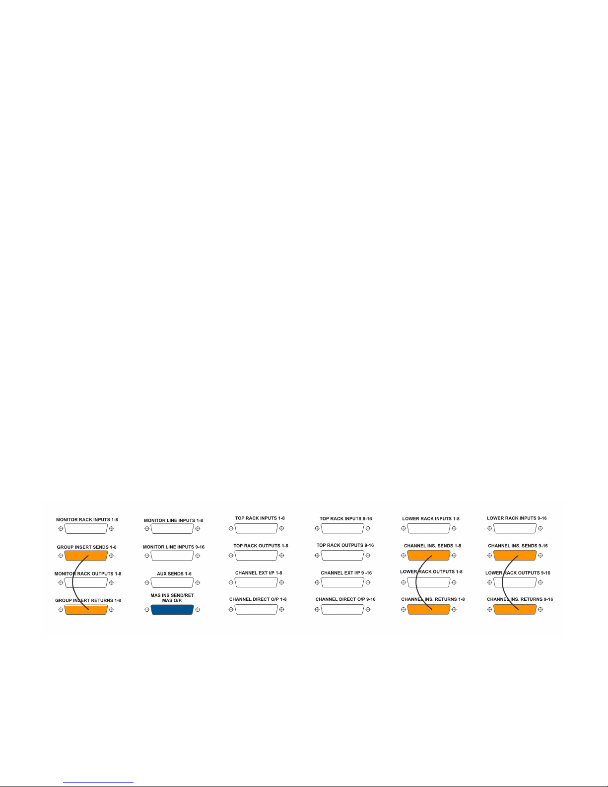
Use a patch bay which normals insert sends to lower rack inputs, and another patch bay which normals
lower rack outputs to insert returns. So, the lower rack 500 series modules (most likely EQ or
compressor) are connected to the insert points.
If you want to bypass the lower rack modules, you simply connect insert send and return on the patch
bay.
Combined with this, you can have a patch bay which normals the group insert sends to the monitor rack
inputs; and another patch bay which normals the monitor rack outputs to the group insert returns (the
monitor racks can for example hold compressor modules).
This way, you’ll have a standard set up, but you still have the possibility to patch any module to any
channel or group.
That is the strength of the Ark.
It not only allows you to fill it up with your preferred 500 series modules, and have the “colour” you want;
but by using a patch bay, you can actually use any module - or chain of modules - on any channel or
group. (now try that with a traditional analogue console)
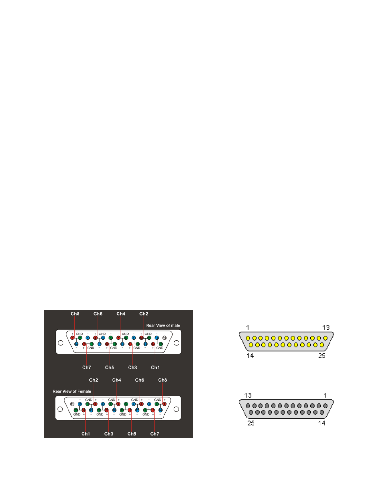
Please see the section on “Audio Connections - Wiring” for correct wiring instructions of all D-Sub
connectors.
Important Notes :
* The D-Sub connectors on the Ark are analogue audio connectors.
DO NOT connect them to digital D-Sub connectors (such as can be found on some DAW
interfaces) or bad things can happen.
* D-Sub connectors are - by design - per 8 channels.
If you have only a couple of 500 modules installed (less than 8), you need to make sure that you
pass signal through the “empty” slots of the console.
If you don’t use a patchbay, you can use D-Sub to XLR cables to make all connections.
You can also use the Ocean Audio 500 I/O connect.
The 500 I/O connect is a 500 series module without any components. It just links the input to the
output, and is inserted in the unused slot.

Ark 500 range - Owner’s Manual - Revision 2.2 - page 10
Audio connections
The console uses 25 way ‘D-Sub’ connectors which follow the Tascam standard for audio wiring. This
universal standard makes it compatible with any other piece of professional analogue audio equipment
(such as patchbays etc.) that follow this standard.
It is also possible to construct cables using the IDC (insulation displacement connector) technique
using .05” ribbon cable. This makes it very quick and simple to manufacture interface cabling for the
console.
All connections to the console require male D-Sub connectors.
As the connections follow the Tascam wiring convention and the majority of connectors provide 8
balanced audio signals, wiring for these connectors is identical.
A table on the next page details the wiring convention.
There are only four exceptions to this:
1) the master left/right inserts and master outputs connector on Ark 504 and 516
2) the control room, alternate monitors and studio playback connector on Ark 504 and 516
3) the 2 track returns connector on Ark 504 and 516
4) the auxiliary sends connector on Ark 504 and 516
They still follow the standard wiring convention but either do not have all 8 signal pairs wired or require
detail for left/right signals. Consequently these have their own wiring sheets which are shown
individually.
Male Connector
Female Connector

Ark 500 range - Owner’s Manual - Revision 2.2 - page 11
4.1 Standard D-Sub pin connections (Ark 504, 516, 508 Ex and 516 Ex)
Pin
Number
Description
1
Channel 8 +
2
Channel 8 Earth
3
Channel 7 -
4
Channel 6 +
5
Channel 6 Earth
6
Channel 5 -
7
Channel 4 +
8
Channel 4 Earth
9
Channel 3 -
10
Channel 2 +
11
Channel 2 Earth
12
Channel 1 -
13
No Connection
14
Channel 8 -
15
Channel 7 +
16
Channel 7 Earth
17
Channel 6 -
18
Channel 5 +
19
Channel 5 Earth
20
Channel 4 -
21
Channel 3 +
22
Channel 3 Earth
23
Channel 2 -
24
Channel 1 +
25
Channel 1 Earth

Ark 500 range - Owner’s Manual - Revision 2.2 - page 12
4.2 Master Insert Sends, Returns & Master Outputs D-Sub connections
(Ark 504 and 516)
Pin
Number
Description
1
No Connection
2
No Connection
3
No Connection
4
Stereo Master Output Left +
5
Stereo Master Output Left Ground
6
Stereo Master Output Right -
7
Stereo Master Insert Return Left +
8
Stereo Master Insert Return Ground
9
Stereo Master Insert Return Right -
10
Stereo Master Insert Send Left +
11
Stereo Master Insert Send Right Ground
12
Stereo Master Insert Send Right-
13
No Connection
14
No Connection
15
No Connection
16
Earth
17
Stereo Master Output Left -
18
Stereo Master Output Right +
19
Stereo Master Output Right Ground
20
Stereo Master Insert Return Left -
21
Stereo Master Insert Return Right +
22
Stereo Master Insert Return Left Ground
23
Stereo Master Insert Send Left -
24
Stereo Master Insert Send Right +
25
Stereo Master Insert Send Left Ground
Following Standard Tascam Audio Connections:
Channel 1: Master Insert Send Right
Channel 2: Master Insert Send Left
Channel 3: Master Insert Return Right
Channel 4: Master Insert Return Left
Channel 5: Master Output Right
Channel 6: Master Output Left
Channel 7: No Connection
Channel 8: No Connection

Ark 500 range - Owner’s Manual - Revision 2.2 - page 13
4.3 Control Room, Alt Mon & Studio Playback D-Sub pin connections
(Ark 504 and 516)
Following Standard Tascam Audio Connections:
Channel 1: Control Room Right
Channel 2: Control Room Left
Channel 3: Alt 1 Right
Channel 4: Alt 1 Left
Channel 5: Alt 2 Left
Channel 6: Alt 2 Right
Channel 7: Studio Play Right
Channel 8: Studio Play Left
Pin
Number
Description
1
Studio Play Left +
2
Studio Play left Ground
3
Studio Play Right -
4
Alt Speaker 2 Left +
5
Alt Speaker 2 Left Ground
6
Alt Speaker 2 Right -
7
Alt Speaker 1 Left +
8
Alt Speaker 1 Left Ground
9
Alt Speaker 1 Right -
10
Control Room Left +
11
Control Room Left Ground
12
Control Room Right -
13
Empty
14
Studio Play Left -
15
Studio Play Right +
16
Studio Play Right Earth
17
Alt Speaker 2 Left -
18
Alt Speaker 2 Right +
19
Alt Speaker 2 Right Ground
20
Alt Speaker 1 Left -
21
Alt Speaker 1 Right +
22
Alt Speaker 1 Right Ground
23
Control Room Left -
24
Control Room Right +
25
Control Room Right Ground

Ark 500 range - Owner’s Manual - Revision 2.2 - page 14
4.4 2-Track Returns D-Sub pin connections (Ark 504 and 516)
Following Standard Tascam Audio Connections:
Channel 1: 2 Track 1 Return Left
Channel 2: 2 Track 1 Return Right
Channel 3: 2 Track 2 Return Left
Channel 4: 2 Track 2 Return Right
Channel 5: No Connection
Channel 6: No Connection
Channel 7: No Connection
Channel 8: No Connection
Pin
Number
Description
1
No Connection
2
No Connection
3
No Connection
4
No Connection
5
No Connection
6
No Connection
7
2 Track 2 Return Right +
8
2 Track 2 Return Ground
9
2 Track 2 Return Left -
10
2 Track 1 Return Right +
11
2 Track 1 Return Right Ground
12
2 Track 1 Return Left -
13
No Connection
14
No Connection
15
No Connection
16
No Connection
17
No Connection
18
No Connection
19
No Connection
20
2 Track 2 Return Right -
21
2 Track 2 Return Left +
22
2 Track 2 Return Left Ground
23
2 Track 1 Return Right -
24
2 Track 1 Return Left +
25
2 Track 1 Return Left Ground

Ark 500 range - Owner’s Manual - Revision 2.2 - page 15
4.5 Auxiliary Sends D-Sub pin connections (Ark 504 and 516)
Following Standard Tascam Audio Connections:
Channel 1: Aux Send 1
Channel 2: Aux Send 2
Channel 3: Aux Send 3
Channel 4: Aux Send 4
Channel 5: Aux Send 5
Channel 6: Aux Send 6
Channel 7: No Connection
Channel 8: No Connection
Pin
Number
Description
1
No Connection
2
No Connection
3
Aux Send 7 -
4
Aux Send 6 +
5
Aux Send 6 Earth
6
Aux Send 5 -
7
Aux Send 4 +
8
Aux Send 4 Earth
9
Aux Send 3 -
10
Aux Send 2 +
11
Aux Send 2 Earth
12
Aux Send 1 -
13
No Connection
14
No Connection
15
No Connection
16
No Connection
17
Aux Send 6 -
18
Aux Send 5 +
19
Aux Send 5 Earth
20
Aux Send 4 -
21
Aux Send 3 +
22
Aux Send 3 Earth
23
Aux Send 2 -
24
Aux Send 1 +
25
Aux Send 1 Earth

Ark 500 range - Owner’s Manual - Revision 2.2 - page 16
5. Input Module (Ark 504, 516, 508 Ex and 516 Ex)

Ark 500 range - Owner’s Manual - Revision 2.2 - page 17
Input module operational description (Ark 504, 516, 508 Ex, 516 Ex)
The Ark input module is an extremely versatile channel strip that provides all the facilities necessary for multi-
track recording and mixing.
All of the switches / pushbuttons are illuminated when activated.
Exception to this are the pre/post switches for the Aux sends.
At the top of the module, eight pushbuttons route the signal to the 8 sub groups in odd
and even pairs.
If required, the channel pan control can be used to direct the signal to an individual sub
group by turning it fully left for an odd numbered sub group or fully right for an even
numbered sub group.
A further pushbutton routes the signal to the master left/right outputs and again by using
the channel pan control, the signal can be routed to either the left or right master output.
The meter switch allows it’s associated VU meter to read either the channel direct output
signal when non illuminated or the signal feeding the channel monitor section when the
button is depressed (illuminated). These individual channel metering select switches
work in conjunction with the master meter switch located at the top of the master module.
Please check the "More on Metering" section of this manual for details.
Below the meter switch is the channel input level control. It is continuously variable with a
convenient centre detent (click) position which denotes that the control is set for ‘0’
meaning that the input is set for unity gain. Attenuation of up to -15db is provided so that
the input signal can be matched for high levels often encountered from some DAW
systems. Gain of up to +10db is provided so that low level signals can be brought up to
provide suitable recording levels.
Next to the input level control is the input selection between two balanced input sources
referred to as ‘External Input’ or ‘Line Input’. This actually emulates the mic/line input
switching of a conventional analogue recording console.
A typical example of this might be where the ‘External Input’ is connected to a 500 series
slot containing a microphone pre-amplifier while the ‘Line Input’ is connected to the
output of a DAW multi-track system, possibly going through another 500 series slot
hosting an EQ for example.
Situated below the input level controls are the six auxiliary sends.
These consist of four mono (auxiliaries 1-4) and one stereo (auxiliaries 5-6.)
All auxiliaries can be selected pre or post fader.
Additionally, auxiliary sends 1 and 5-6 can be routed to the channel monitor section, thus
providing auxiliary send facilities from the monitor section.
Below the auxiliary sends is the channel monitor section. This is in effect another
independent input channel that operates separately from the main one. The purpose of
the channel monitor section is to provide a means of monitoring the replay signal from a
DAW or other recording device (such as a good old analogue multi-track tape recorder).
Using the direct outputs as sends to the multitrack and the channel monitor section as
returns it is possible to monitor the send (input) and replay (output) to the multi-track
recorder. Used in conjunction with the meter switching as described above, this feature
provides a very flexible and convenient way to record multi-track.
The input to the channel monitor section is balanced and the signal level can be
controlled via the ‘Mon Level’ control. A ‘Mon Pan’ control allows the signal to be panned
between the master left and right outputs. This has a centre detent (click) so that it is
easy to find the central position. Also provided are a solo (after fade listen) switch so that
the signal can be heard in isolation and is non destructive; and mute switch that kills the
channel monitor signal.

Ark 500 range - Owner’s Manual - Revision 2.2 - page 18
As previously mentioned, auxiliaries 1 and 5-6 can be “moved” to the channel monitor
section so that they are no longer a part of the input section. So you can actually split the
AUX sends. 3 on the channel input, and 3 on the monitor section.
This allows you to provide a headphone or effect send mix from the channel monitor
section.
The advantage of providing a headphone mix from the channel monitor section is that
when building up a multi-track recording and overdubbing signals, the artist will always be
able to hear both what has been recorded and what they are about to record. This greatly
adds to the continuity of the recording process.
A complete multi-track mix can therefore be built up on the channel monitor section very
easily during multi-track recording.
Below the channel monitor section is the input channel pan control which has a centre
detent (click) so that it is easy to find the central position and a large illuminated mute
switch.
A ‘Solo’ switch mutes all other channels but the one selected.
This performs like a Solo-in-Place (SIP). All other channels will be muted and those mute
switches will illuminate. Since all other channel signals are muted, this is also referred to
as ‘destructive’. Be careful when using this during mixdown since it will alter the mix
feeding the left/right master outputs.
A ‘PFL’ switch (pre-fader listen) gives you the signal in isolation before the channel fader
and pan as a quick and easy method of checking if there is signal present. As it is pre-
fader and pan, the signal appears on the monitor speakers in mono.
An ‘AFL’ (after-fader listen) switch provides a stereo after fader and pan signal which is
useful for checking the stereo position or channel signal in isolation. Both the ‘PFL and
AFL’ switches are non destructive, which means that they can be used during a mix
without affecting the main signal.
Below every channel is a high quality fader for precise control of signal level.
Reference to the signal flow diagram will give a better understanding of the input
module’s features and facilities.

Ark 500 range - Owner’s Manual - Revision 2.2 - page 19

Ark 500 range - Owner’s Manual - Revision 2.2 - page 20
6. Submaster Module (Ark 504 and 516)
Other manuals for The Ark 500 Series
1
Table of contents
Other OceanAudio Music Mixer manuals