Oceanic OCEACDKI001 User manual

COLONNE DE DOUCHE
Notice
SHOWER COLUMN
OCEACDKI001
www.oceanic.eu
Instruction booklet

- Pression minimum : 1 bar / maximum : 5 bars (au-delà, monter
un réducteur de pression).
- S’assurer que les pressions d’alimentation de l’eau chaude et
de l’eau froide sont bien équilibrées.
- Température conseillée pour le réglage de l’installation d’eau
chaude : 60°C (maximale : 80°C)
- Température d’eau froide minimale : 10°C (une température
inférieure endommagerait votre robinet).
Une eau très dure est fortement chargée en calcaire ce qui
accélère l’entartrage de votre robinetterie.
Le traitement de votre eau avec un adoucisseur permet de
protéger vos installations et prolonger la durée de vie de votre
équipement.
Condition d’utilisation
Avant toute manipulation, assurez-vous de la présence de tous les
composants et vérifiez visuellement leur bon état de surface. Au
moment du montage et/ou de l’installation, assurez-vous qu’en
respectant bien les éventuelles consignes, vous ne rencontrez
pas de difficulté de vissage, serrage, emboîtage.
Déballage
[Schéma partie 2]
- Placer les joints dans les connecteurs femelles du mitigeur
avant de serrer les écrous du mitigeur.
- Lors de la première utilisation, assurez-vous du fonctionnement
de votre produit (en particulier que l’eau s’écoule à la bonne
température et avec le bon débit).
NB : Pour le raccord à votre installation : bien serrer le raccord ou
les écrous à l’aide d’une clef. Eviter tout serrage excessif,
susceptible de casser le filetage ou de provoquer des micro-
fissures qui pourraient s’élargir avec le temps et la pression de
l’eau et provoquer une fuite.
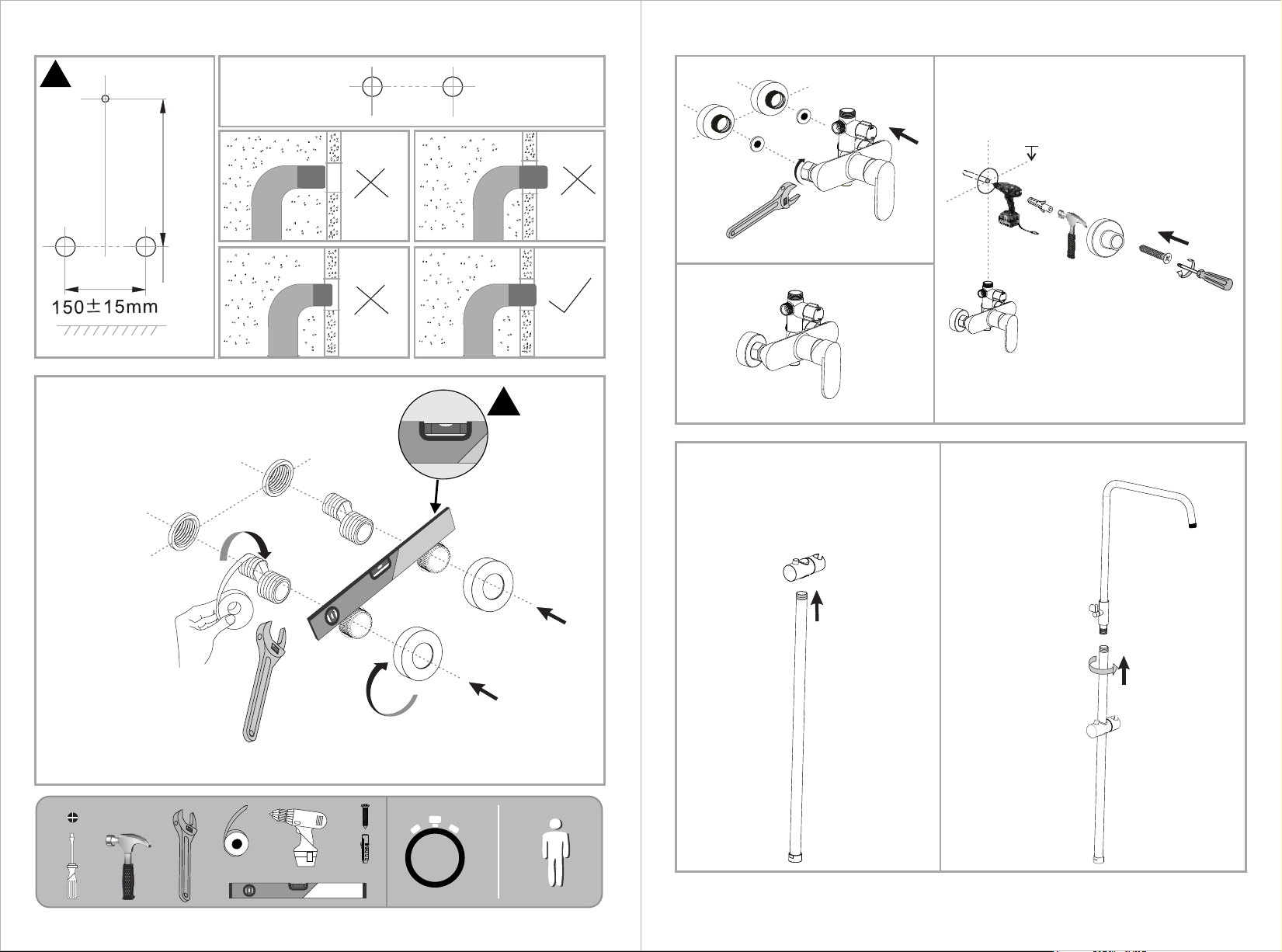
[Schéma partie 3]
La colonne de douche nécessite un point de fixation mural.
- Identifiez ce point de fixation dans le prolongement vertical de la
sortie d’eau supérieure du mitigeur. Pour la hauteur de ce point
réferrez-vous aux mesures fournies plus bas dans le schéma.
- Percez le mur à l’aide d’un forêt de diamètre 6mm pour une
profondeur de 40 mm pour y introduire une cheville adaptée au
matériau de votre mur.
- Positionnez le support de fixation de la colonne à l’aide de la vis
adaptée.
[Schéma partie 4]
- Introduisez le support mural le long de la colonne de manière a
ce que le bouton de déverrouillage soit orienté vers le haut
[Schéma partie 5]
- Vissez la partie haute de la colonne dans sa partie basse
[Schéma partie 6]
- Enclenchez la colonne dans le point de fixation mural
- Enclenchez également la partie basse de la colonne en y
insérant le joint d’étanchéité.
- Serrez la partie basse à l’aide d’une clé
[Schéma partie 7]
- Serrez le support de fixation mural à l‘aide de la clé Allen fournie
- Raccordez le flexible à la partie basse de la colonne et serrez à
l’aide d’une clé
- Vissez le pommeau de douche à l’autre extrémité du flexible
- Vissez la tête de douche à la colonne
[Schéma partie 1]
- Lors du montage, les filetages ne doivent pas être endommagés
(les écrous doivent pouvoir se visser librement). A défaut,
l’étanchéité ne serait pas parfaite.
- Placer du ruban en PTFE (tel que Teflon) sur les raccords
excentrés mâle-mâle pour assurer l’étanchéité, puis visser les
dans les conduits d’alimentation en eau chaude et en eau froide
au niveau du mur pour les faire correspondre avec l’écartement
des connections du mitigeur. Vérifier l’horizontalité des
connecteurs au moment de leur serrage.
- Placer les rosaces sur les connecteurs.
Déballage

[Drawing part 1]
- During assembly, the connection threads must not be damaged
(it must be easy to screw the nuts on the threads).
- Place a PTFE ribbon (such as Teflon) on the offset male-male
connectors to ensure the watertightness, then screw them into the
hot and cold water supply hoses inside the wall and make them
correspond to the distance between the connectors of the mixer.
Check the level of the connectors during the fastening, it must be
horizontal.
- Place the cover cups on the connectors.
[Drawing part 2]
- Place the gasket into the female connectors of the mixer before
to proceed to the tightening.
- When using for the first time, make sure that your product is
working (in particular that the water flows at the right temperature
and with the right flow rate).
Installation
- Minimum pressure: 1 bar / maximum: 5 bars (beyond, install a
pressure reducer).
- Make sure that the supply pressures for hot and cold water are
well balanced.
- Recommended temperature for adjusting the hot water
installation: 60 ° C (maximum: 80 ° C)
- Minimum cold water temperature: 10 ° C (a lower temperature
would damage your tap). Very hard water is heavily loaded with
lime stone which accelerates the scaling of your taps.
Treating your water with a softener helps protect your facilities and
extend the life of your equipment.
Terms of use
Before handling, make sure that all components are present and
visually check their good surface condition.
When mounting and / or installing, make sure that by respecting
any instructions, you do not experience any difficulty in screwing,
tightening, fitting.
Unpacking
Le bon fonctionnement du robinet nécessite donc un entretien
régulier.
Nous vous recommandons de :
- ne jamais utiliser de produits abrasifs ou corrosifs. Ces produits
agressifs attaquent les revêtements et ternissent votre robinet.
- nettoyer la surface chromée en utilisant un détergent doux ou de
l’eau savonneuse et un chiffon doux en veillant à rincer
correctement à l’eau claire après nettoyage.
- nettoyer régulièrement la tête du robinet (au moins 1 fois par
an), à l’aide d’une solution eau et vinaigre blanc (laisser reposer
une nuit).
- nettoyer l’aérateur-mousseur en le trempant dans une solution
eau/vinaigre blanc.
- actionner les pièces mobiles (inverseur, manette, croisillon,
tirette) au moins une fois par semaine afin de garantir le bon
fonctionnement dans le temps.
Entretien / nettoyage
Le mitigeur permet d’utiliser soit la tête de douche, soit le flexible.
Pour passer de l’un à l’autre cela dépend de l’orientation du
sélecteur sur la partie basse de la colonne. Les symboles sur le
sélecteur indiquent le mode correspondant.
Utilisation

NB : For the fitting to your installation: tighten the fitting or the nuts
securely using a wrench. Avoid excessive tightening, which could
break the thread or cause micro cracks which could expand over
time and the pressure of the water and cause a leak.
[Drawing part 3]
- Identify this fastening point vertically aligned with the water
output on the top of the mixer. For the height, see the the
measurements given in the drawing.
- Drill the wall with 6mm bit with a 40 mm depth in order to
introduce a suitable wall plug into it according to the material of
your wall.
- Place the wall fastening support of the column with the suitable
screw.
[Drawing part 4]
- Insert the wall fastening element. Ensure that the unlocking
button is turn up.
[Drawing part 5]
- Screw the top part of the column into the lower part
[Drawing part 6]
- Engage the column into the wall fastening support
- Engage the lower part of the column into the mixer top connector
with the gasket in between to ensure the water tightness
- Tighten the lower part to the connector with a wrench
[Drawing part 7]
- Tighten the wall fastening support with the hex key
- Connect the flexible to the mixer and tighten with a wrench
- Connect the head of the flexible
- Screw the shower head on the column
The proper functioning of the tap therefore requires regular
maintenance.
We therefore recommend:
- never use abrasive or corrosive products. These aggressive
products attack coatings and tarnish your faucet.
- clean the chrome surface using a mild soap or soapy water and a
soft cloth making sure to rinse well with clean water after cleaning.
- regularly clean the cartridge / tap head (at least once a year),
using of a solution of water and white vinegar (let stand overnight).
- clean the aerator-aerator by soaking it in a water / white vinegar
solution.
- activate the moving parts (inverter, lever, crosspiece, pull tab) at
least once per week to ensure smooth operation over time
Maintenance / cleaning
The mixer allows you to use either the column head or the hose. To
switch from one to the other, it depends of the position of the
selector on the lower part of the column. The symbols on its
surface inform you about the mode.
Use

776 85-445
130
45
466
255 190
G1/2
150
Ø60
1500
G1/2
G1/2
57
145
Produit d'installation n ° 1
OCEACDKI001 OCEACDKI001
325
Ø20
Ø24
210

776±2mm
!
①
②
④
③
⑤
Ø6 40mm
#30
Chaud
Froid
!
G1/2
#14
1hour

Fonction:
⑥
#23
#23
⑦

IMPORTANT: pour la fixation murale, utiliser des vis et des
chevilles adaptées à la nature du mur. En cas de doute, contacter
votre magasin de bricolage.
FIXATIONS MURALES / WALL MOUNTING
!
IMPORTANT: for the wall support fixation kit, use screws and wall
plugs adapted to the nature of the wall, in case of any doubt
please contact your DIY store.
Attention: bien veiller à respecter l'ensemble de la notice de montage.
Beware : Follow carefully the assembly instructions.
!II existe une grande diversité de types de murs ou cloisons,
c'est la raison pour laquelle nous ne pouvons vous fournir le
type exact de fixation. Il est nécessaire d'identifier le type
de paroi à laquelle vous allez fixer ce produit afin d’utiliser
les fixations appropriées. Voici quelques exemples de
fixations conseillées. Les vis et chevilles pour fixer le
support au mur ne sont pas incluses. Choisissez des vis et
chevilles adaptées au matériau de votre mur. En cas de
doute, demandez à un vendeur spécialisé.
!There is a large diversity of all types, therefore we do not
provide the exact fastening type with the product. You need
firstly to identify the type of your wall in order to find the
suitable fastening type. Here are several example of wall
types and the recommended fastening type. The screws
and wall plugs are not included. Choose the proper screw
and wall plug according to your wall material. In case of
doubt, contact a specialized seller.
LES MURS PLEINS / SOLID WALL
CHEVILLE NYLON “FISCHERE”
NYLON WALL PLUG
CHEVILLE D’ANCRAGEMETAL
METALLIC ANCHOR
LES CLOISONS CREUSES / HOLLOW WALL
CHEVILLE
D’ANCRAGE A
AILETTES EN NYLON
NYLON HOLLOW WALL
EXPANSION PLUG
CHEVILLE
METALLIQUE A
EXPANSION
HOLLOW WALL
EXPANSION ANCHOR
CHEVILLEMOLLY
“MOLLY”
MOLLY BOLT ANCHOR
Utiliser une taille de forêt adaptée à la quincaillerie
utilisée et au type de mur.
Use a drill bit size suitable with the monger and the type
of wall.
Other Oceanic Bathroom Fixture manuals
Popular Bathroom Fixture manuals by other brands

Delta
Delta B3310LF installation instructions

Delta
Delta Ixa Jive 44020-SQ quick start guide

vismaravetro
vismaravetro Junior GN Assembling instructions

Delta
Delta B912912-4836-SS quick start guide

Dreamline
Dreamline PRISM PLUS SHEN-2634340 Series installation instructions

PULSE+
PULSE+ Tropicana ShowerSpa 1039W-BN owner's manual

Delta
Delta 54446 PK Series installation instructions

mr. steam
mr. steam MX4E Installation, operation and maintenance manual

Delta
Delta Grail 25225 quick start guide

Delta
Delta Nicoli 35849L Series quick start guide

Delta
Delta EMMETT 21742LF-SP manual

LIVARNO LUX
LIVARNO LUX 305977 Assembly, operating and safety instructions