OilQuick OQ 70/55 User manual

OPERATING MANUAL
AND FITTING
INSTRUCTIONS
OilQuick quick coupler with automatic
hydraulic connection for excavators
OQ 70/55 and 80
Specifications subject to change without notice.
Please read the instructions carefully
before using the quick coupler.

Dear Customer,
We congratulate you on your purchase of an OilQuick quick coupler system.
OilQuick is the most advanced quick coupler system for excavators and can be supplied in various models for
machines from 1 to 120 tons.
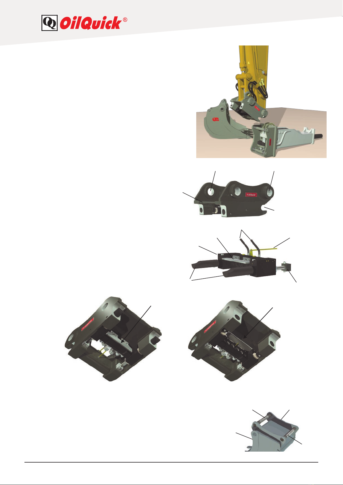
The modular OilQuick system is available as a standard hydraulic hitch or also with OilQuick function, which
allows hydraulic attachments to be connected or disconnected automatically from inside the cab.
Hydraulic attachments that can be used include Grab John buckets, tiltrotators, compactors, sorting grapples
and hydraulic hammers.
The OQ 70/55 model is suitable for excavators from 18 to 28 tons operating weight.
The OQ 80 model is suitable for excavators from 25 to 45 tons operating weight.
OilQuick products bear the CE marking and comply with all the applicable safety regulations.
When installing, using and repairing OilQuick quick coupler systems, please ensure that you meet all the
requirements.
Changes may only be made to OilQuick quick coupler systems with the approval of OilQuick AB.
Any unauthorized changes will void the warranty and CE-marking.
Please send us the completed warranty card as soon as possible.
We hope you enjoy the benefits and wish you every success with your new OilQuick quick coupler system.
Introduction
These instructions apply to models OQ 70/55 and OQ 80.
Components are also described in the instructions that are optional accessories, which you may not have
ordered with your new quick coupler system. Please observe all the safety regulations and ensure that your
equipment is properly maintained. This will minimize the risk of damage and injury.
Subject to change without notice. Errors and omissions excepted.
This is a translation of the original manual.
Copyright © OilQuick AB.
Please read the instructions carefully before mounting and using the quick coupler system.
Information in boxes as illustrated below are
warnings that you should read particularly
carefully and understand.
Ignoring such warnings may result in personal
injury or damage to property.
Example
Information in boxes as illustrated below
contains important notes that you should read
carefully and understand.
Example

Detach here
Registration card for product warranty
The warranty is only valid if your new OilQuick product is installed correctly on the excavator and
attachment. Completing and sending in the registration card to OilQuick AB registers you as the
warranty holder for this product.
Unless otherwise agreed, the warranty terms included in this product manual shall apply.
The identification plate on the product shows details of the product model and serial number.
If you have any questions, please do not hesitate to contact your excavator dealer.
Please send the completed registration card to:
OilQuick AB
Box 1055
82412 Hudiksvall
Sweden
Tel: +46 650 15340
Fax: +46 650 14884
E-mail: information@oilquick.com
Name of excavator dealer:
Name and address of customer:
Tel: Fax:
E-mail:
OilQuick quick coupler model:
Serial no.:
Excavator model: Excavator weight:
Date installed:
Hydraulic attachments used:
Received by OilQuick AB on:


Declaration of Conformity
The company OilQuick AB
Box 1055
SE-824 12
Hudiksvall
SWEDEN
hereby certifies that the quick coupler system
Designation Quick Coupler
Type
Serial no.
Year of manufacture
Weight
conforms to the requirements of Machinery Directive
2006/42/EC and the applicable regulations in
European standards EN 474-1, EN 474-4 and
EN 474-5, and machine regulations 2008:3 issued by
the Swedish Work Environment Authority.
Before operating the quick coupler, additional risks
that may arise from mounting the coupling device on a
machine or other type of attachment carrier must be
investigated and compliance with the regulations
stated in the above guidelines determined.
Name Åke Sonerud
Position General Manager
Hudiksvall, Sweden

Version 1.1 62011-06-28
Dear Customer 2
Introduction 2
Registration card for product warranty 3
Contents 5
Declaration of Conformity 6-7
1. OilQuick quick coupler system components 8
1.1 Coupler part 8
1.2 H-cylinder 8
1.3 Attachment frame for mechanical tools 8
1.4 Attachment frame for hydraulic tools 9
1.5 V-90 electric coupling (option) 9
1.6 1/2" electric coupling (option) 9
1.7 Locking hydraulic kit (option) 9
2. Quick coupler functionality 10
3. H-cylinder –function and requirements 11
4. Technical data 12
4.1 General data 12
4.2 Quick coupler 12
4.3.1 Attachment frame for mechanical tools without coupling ramp 13
4.3.2 Attachment frame for hydraulic tools with coupling ramp 13
4.3.3 Hydraulic tool adapter plate with coupling ramp 13
4.3.4 Hydraulic tool special adapter with coupling ramp 13
5. Quick coupler installation 14
6. Hydraulic system installation 15
7. Coupling an attachment 16-17
7.1 Checking hydraulic tools 17
7.2 Checking mechanical tools without hydraulic system 17
8. Lock test for mechanical tools 18
9. Setting down a tool 18-19
10. Using the hoisting hook 20
Contents

Version 1.1 72011-06-28
11. Checking the attachment frame 21-22
12. Starting and stopping the excavator for maintenance work 22
13. Inspection and maintenance 23
13.1 Daily inspection 23
13.1.1 At the start of the working day 23
13.1.2 At the end of the working day 23
13.2 Monthly inspection 23
14. Maintenance of quick couplers on H-cylinders 24
14.1 Replacing the nose seal in the female connector 24
14.2 Replacing quick couplers secured with circlips 25
14.3 Replacing quick couplers secured with nose nuts 26
15. Troubleshooting 27
16. Plates and stickers 28
17. Terms of warranty 29

Version 1.1 82011-06-28
1
2
3
4
13
1412
11
1.3 Attachment frame for mechanical tools
11. Attachment
12. Front frame pin
13. Rear frame pin
14. Side part
1.2 H-cylinder
5. H-cylinder
6. Cylinder holder
7. Hydraulic hoses for locking and unlocking
8 Locking plungers
9 Indicator rod
10. Dirt guard 8
5
9
7
6
10
10 10
1. OilQuick quick coupler system components
The following section describes the various components in
the OilQuick quick coupler system.
1.1 Quick coupler body
1. Coupler body
2. For attaching to the excavator arm
3. For attaching to the linkage
4. Fingers
Dirt guard closed Dirt guard open

Version 1.1 92011-06-28
1.7 Locking hydraulic kit (option)
24. Control switch with double command function
25. Alarm
26. Electric selector valve, 4/2
27. Cable set
28. Electric connection
Use this kit when a hydraulic lock has not yet been installed on the machine or OilQuick's requirements
for hydraulic locking has not been met (see section 3).
25
26
24
27
28
15
19
16
17
18
1.4 Attachment frame for hydraulic tools
15. Attachment frame
16. Coupling ramp
17. Male connector
18. Front pin
19. Rear pin
The attachment frames are available in various models for different applications, but the function is the same
as for the basic model in each case. For further details, please contact your nearest OilQuick dealer.
20
21
1.5 V-90 electric coupling (option)
20. Contact socket
21. Contact plug
The contact elements are 10 pin.
22
23
1.6 1/2" electric coupling (option)
22. Contact socket
23. Contact plug
The contact elements are 10 pin.
20
21
23
22

Version 1.1 10 2011-06-28
1
4
2
3
5
7
2. Quick coupler functionality
The quick coupler consists of a basic coupler part (1) with the H-cylinder (2) and various accessories
mounted on it. It is attached to the excavator arm and linkage. The H-cylinder (2) and locking plungers (3) are
moved backwards and forwards (4) when oil is supplied to the H-cylinder. When the H-cylinder is located at
the front position (4:1), the locking plungers are not visible and an attachment can be connected or discon-
nected. When the H-cylinder is located at the rear position (4:2), the locking plungers are visible and an at-
tachment
frame can be connected to the coupler.
The hydraulic quick couplers are located in the middle of the H-cylinder between the locking plungers.
Models OQ 70/55 and OQ 80 can be fitted with two 1/2", two 3/4" and two 1" quick couplings.
A dirt guard (5) prevents the quick couplers from becoming dirty. It is opened automatically when the
H-cylinder is at the front position (4:1) and closed automatically at the H-cylinder's rear position (4:2).
The system installed on the excavator for the hydraulic quick coupler supplies oil to the H-cylinder (2).
The operator only has to take a look at the indicator rod (6) to check the H-cylinder's position.
When the indicator rod (6) is visible, the H-cylinder (2) is at its front position and the quick coupler is
unlocked. In this case an alarm sounds and a warning light comes on in the cab.
When the indicator rod (6) is not visible, the quick coupler is closed or locked with an attachment frame.
In this case there is no acoustic signal and the warning light does not come on.
When a hydraulic tool (7) is coupled, the hydraulic quick couplers are connected and the attachment is
mechanically locked.
6 6
4:1
4:2

Version 1.1 11 2011-06-28
1
3. H-cylinder –function and requirements
The H-cylinder is the key component in the quick coupler.
When working with a hydraulic attachment, the H-cylinder must ensure that the tool is securely attached and
the hydraulic couplings are properly connected.
The hydraulic circuit diagram for the H-cylinder is shown below.
1. Locking cylinder
2. Pilot-controlled check valves
3. Pressure controller
4. Control valve for the
excavator's quick coupler system
5. Hydraulic pump
6. Hydraulic tank
In today's excavators, both the pressure and the oil flow from the machine's hydraulic pump (5) change in
relation to the excavator load. Unlike many other systems, the OilQuick quick coupler system operates at the
excavator's maximum working pressure. This is necessary to ensure that the coupler part is securely locked
to the attachment frame on the tool with no play. In addition, the H-cylinder guarantees that the quick
couplers are connected properly. When the tool is attached, the pressure on the positive side of the cylinders
(1) builds up to the maximum level for the machine.
If the machine pressure changes, the two pilot-controlled check valves (2) ensure that the pressure in the
cylinders (1) remains constant. Whenever the pump pressure (5) rises, oil is supplied to the cylinders (1).
If the pressure in the cylinders (1) exceeds 45 MPa, the control valves (3) open on the tank side (6) and
reduce the pressure.
When the quick coupler unlocks for disconnecting the attachment, the control valve (4) is operated.
In this case, the H-cylinder's negative side is pressurized, the pilot-controlled check valves (2) open and the
H-cylinder releases the lock. If oil supply to the H-cylinder is stopped (e.g in case of hose rupture), it is pre-
vented to be opened as the pilot operated check valves (2) ensure that existing oil can not leave the
H-cylinder without pressure on the negative side.
The H-cylinder in the OilQuick quick
coupler system must:
be directly connected to the pump
have an open return line to the tank
lock at the maximum pressure for
the excavator's hydraulic system
H-cylinder

Version 1.1 12 2011-06-28
1 2 3 4 5 6
4. Technical data
4.1 General data
The quick couplers design follows S-standard for attachment frames.
Hydraulic oil: class HM, HV to CETOP RP 91 H in viscosity grades: ISO VG 32, 46 and 68.
Oil temperature: -30°C to +80°C.
Ambient temperature: -25°C to +55°C.
4.2 Quick coupler QO 70/55 OQ 80
Max. output torque kNm (M) 450 700
Bucket radius mm (L1) 1550 1850
Force at bucket edge kN (F) 290 380
M (kNm) = F (kN) x L1(m)
Width (mm) 550 590
Weight (approx, kg) 230 320
(see identification plate, depends on excavator)
Quick coupler with 2 parallel hydraulic cylinders
Max. working pressure (MPa) 35 35
Load-bearing hose break valves yes yes
Pressure control valves yes yes
Piston rod diameter (mm) 55/30 55/30
Stroke (mm) 75 75
Total closing force at 100 bar (kN) 47.5 47.5
Leak-free quick couplers made of steel, OilQuick
Coupling sizes 1/2” 3/4” 1”
Oil flow at 0.3 MPa pressure loss (l/min) 70 140 250
Max. continuous working pressure (MPa) 35 35 35
No. of couplings
OQ 70/55 2 2 2
OQ 80 2 2
V-90 electric coupling yes yes
1/2" electric coupling yes yes
Quick coupling location
The quick couplers must be visible from the cab.
Couplings 1 and 6: 1/2"
Couplings 2 and 5: 3/4"
Couplings 3 and 4: 1"
If the excavator is fitted with a 1/2" electric coupling, it replaces hydraulic coupling no. 1.
The couplings fitted may vary and depend on the excavator's hydraulic system and what attachments
are to be used.
For further details, please contact your nearest OilQuick dealer.

Version 1.1 13 2011-06-28
4.3.1 Attachment frame for mechanical tools without coupling ramp
OQ 70/55 OQ 80
Inside width (mm) 550 590
Pin distance (mm) 600 670
Pin diameter (mm) 70 80
Weight (kg) 90 160
OilQuick attachment frames for mechanical tools follow S-standard and can also be used together with other
quick couplers which follow the same S-standard (N.B This operating manual is only valid for OilQuick quick
couplers).
4.3.2 Attachment frame for hydraulic tools with coupling ramp
OQ 70/55 OQ 80
Inside width (mm) 550 590
Pin distance (mm) 600 670
Pin diameter (mm) 70 80
Weight (kg) 100 170
4.3.3 Hydraulic tool adapter plate with coupling ramp
OQ 70/55 OQ 80
Inside width (mm) 550 590
Pin distance (mm) 600 670
Pin diameter (mm) 70 80
Weight (kg) 325 465
4.3.4 Hydraulic tool special adapter with coupling ramp
OQ 70/55 OQ 80
Inside width (mm) 550 590
Pin distance (mm) 600 670
Pin diameter (mm) 70 80
Weight (kg) See identification plate on adapter.
The attachment frames and adapter plates must be installed following the separate instructions
supplied.
If you have any questions, please do not hesitate to contact your OilQuick dealer.

Version 1.1 14 2011-06-28
2
1
5
3
7
6
4
5. Quick coupler installation
When installing the OilQuick quick coupler system, the following
requirements must be met:
The coupler part design must be suitable for the excavator's
arm, linkage and geometry.
The bolts connecting the excavator arm and linkage must be
appropriate and mounted securely.
The pressure side of the hydraulic lock must be directly
connected to the pump at the excavator's maximum working
pressure.
There must be a free return line to the tank on the return
side of the hydraulic lock.
Components of an adequately high or higher pressure class
than the machine's working pressure must be installed for the
hydraulic system.
In addition, the excavator manufacturer's instructions for
mounting quick couplers must be followed.
The quick coupler is delivered in transport packaging to the place
where it will be installed. Do not open this packaging until starting to
mount the quick coupler on the excavator. The packaging protects
the contents from the weather, prevents it from getting dirty and
also makes transport on site easier. When mounting the quick
coupler on the excavator, proceed with caution. Failure to do so
when handling the large, heavy parts may lead to accidents.
8
When working on the hydraulic system, observe the following:
Take care of the environment and collect any oil that has spilled.
Wear gloves. Hydraulic oil can cause allergic reactions if you are exposed to it for longer periods.
Wear goggles to protect yourself from oil splashes.
In the hydraulic system, lines, couplings and connections may be under high pressure.
When working on the hydraulic system, always ensure cleanliness. Contamination in the system may
cause malfunctions.
After installation, carry out the following steps:
Check the hydraulic pressure on the lock side of the H-cylinder (must be the excavator's maximum
pressure).
Check the hydraulic pressure on the open side of the H-cylinder (must be near zero).
Inspect daily (see section 13.1)
Mechanic responsible:
Signature:
Date and place:
1. Tilt cylinder
2. Screw
3. Mounting bolt
4. Shims
5. Quick coupler
6. Hydraulic lock connection
7. Excavator arm
8. Linkage
CAUTION!
When installing the quick coupler, think of the risk of injury.

Version 1.1 15 2011-06-28
Hoses with guide block mounted on
top of the arm.
6. Hydraulic system installation
The attachments are connected to the excavator's hydraulic system with hoses between the quick couplings
on the coupler and the connections on the excavator arm. The hoses should be routed as illustrated below,
but there can be variations depending on the excavator model and type of installation.
When locating the hoses on the arm, ensure that the bend radius is large enough and that they do not rub or
twist.
First just try placing the hose holders and check the length of the hoses. It is important for you to check the
hose routing when the linkage is at both end positions (see illustrations below).
Hose holders are available in various designs for different installation configurations. Our nearest OilQuick
dealer will be happy to help you select a suitable product.
We recommend you use a guide block for connecting the H-cylinder hoses for the hydraulic lock.
This guide block is a practical installation aid, as it enables the hydraulic hoses to be routed behind the
linkage. It has ports for measuring the locking pressure on the H-cylinder.
The hose length depends on the excavator and type of installation.
Hose holder
Guide block with ports for
measuring the pressure on
the H-cylinder.
Hose position when the tilt
cylinders are moved right in
Hose position when the tilt
cylinders are moved right out
Hose position when the tilt
cylinders are in the middle

Version 1.1 16 2011-06-28
7. Coupling an attachment
In the descriptions regarding handling of the quick coupler, we have assumed that an OilQuick locking
hydraulic kit is installed. If this is not the case, proceed as described in your excavator manual when using the
quick coupler.
Procedure for coupling an attachment:
Make sure that everyone is clear of the excavator's
working area.
Open the quick coupler by pressing the lock switch.
The warning light comes on and the alarm sounds.
Move the tilt cylinder right out, enabling pressure to
build up and the H-cylinder to open.
Make sure that the indicator is visible (1).
Make sure that the locking plungers are retracted (2).
1
2
Make sure that the quick coupler and the attachment frame on the tool to be connected are aligned.
Right Wrong
The quick coupler system may only be operated by people who have read the manual and follow
the instructions it contains.
When connecting or disconnecting, changing and setting down attachments, no one should be in
the excavator's working area. During the coupling procedure, attachments may accidentally
become detached or topple over and cause injury.
Lock function
The warning light on the
lock switch is on and an
alarm sounds
In the descriptions regarding handling of the quick coupler, we have assumed that an OilQuick
locking hydraulic kit is installed. If this is not the case, please refer to your excavator manual.
N.B! OilQuick quick couplers can only be coupled to an attachment with an OQ–or
S-attachment frame of the same size/model.

Version 1.1 17 2011-06-28
Move the tilt cylinder in until the quick coupler is at an angle of 30-45 degrees to the attachment frame
on the tool (see illustration below).
Hook the fingers at the front of the quick coupler onto the front attachment frame pin.
Raise the attachment from the ground until it hangs freely.
Move the tilt cylinder out, lowering the rear part of the quick coupler to the rear pin on the attachment.
Disable the lock switch for the quick coupler. The light and the alarm both go off.
Move the tilt cylinder to its end position, enabling pressure to build up and the H-cylinder to lock the
attachment. At the same time any hydraulic and electric couplings in use are connected.
Make sure that the indicator rod is NOT visible (3).
Make sure that the locking plungers are located under the rear pin on the attachment frame (4).
3
4
Right Wrong
7.1 Checking hydraulic tools
Try using a hydraulic function on the attach-
ment. If it works properly, the connection is
correct.
Finished.
7.2 Checking mechanical tools without
hydraulic system
Carry out the lock test as described in section 8.
Finished.
ca 30 cm
30°-45°
You must always check that the attachment
is locked as described in 7.1 or 7.2.
If in doubt, disconnect the attachment and
find the cause.
See also troubleshooting.

Version 1.1 18 2011-06-28
8. Lock test for mechanical tools
When connecting a mechanical attachment without hydraulic function, you have to carry out a lock test
before using the tool for working.
Tilt the attachment forward, press it into the ground and move the tilt cylinder in (see illustration below).
The tool must not become detached in the process.
When connecting or disconnecting, changing and setting down attachments, no one should be in
the excavator's working area.
During the coupling procedure, attachments may accidentally become detached or topple over and
cause injury.
When connecting mechanical attachments, always carry out a lock test.
9. Setting down a tool
In the descriptions regarding handling of the quick coupler, we have assumed that an OilQuick locking
hydraulics kit is installed. If this is not the case, proceed as described in your excavator manual when using the
quick coupler.
When connecting or disconnecting, changing and setting down attachments, no one should be in
the excavator's working area. During the coupling procedure, attachments may accidentally
become detached or topple over and cause injury.
In the descriptions regarding handling of the quick coupler, we have assumed that an OilQuick
locking hydraulic kit is installed. If this is not the case, please refer to your excavator manual.

Version 1.1 19 2011-06-28
Procedure for setting down an attachment:
Make sure that everyone is clear of the excavator's
working area.
Raise the attachment.
Move the tilt cylinder out until the attachment hangs
from the front pin and the rear pin presses against the
coupler part (see illustration below).
1
2
Open the quick coupler by pressing the lock switch. The warning light comes on and the alarm sounds.
Move the tilt cylinder right out, enabling pressure to build up and the H-cylinder to open.
Make sure that the indicator rod is visible (1).
Make sure that the locking plungers are retracted (2).
Move the tilt cylinder out until the attachment only hangs from the front pin. There should be 0-2 cm
play between the rear pin and the coupler part (see illustration below).
Lower the attachment onto the ground. The ground should be hard and even.
Move the tilt cylinder in until the quick coupler is at an angle of 30-45 degrees to the attachment frame
on the tool (see illustration below).
Release the front pin from the attachment frame and raise the boom.
Disable the lock switch for the quick coupler.
Move the tilt cylinder out to its maximum position so that pressure is built up in the machine and the
H-cylinder moves forward and locks the quick coupler. The light and the alarm both turn off. The quick
coupler is locked and the dirt guard is closed, preventing the quick couplings from getting dirty.
Check that the indicator rod is not visible
Make sure that the locking plungers are out (locked position)
Finished.
It is important for the attachment to be tilted inwards.
If it is not, unlocking the H-cylinder could cause it to fall to the ground unchecked.
Lock function
The warning light on the
lock switch is on and an
alarm sounds
30°-45°

Version 1.1 20 2011-06-28
10. Using the hoisting hook
The OilQuick coupler part is fitted with a safety hook for lifting work on site.
The maximum load capacity is affected by two factors:
1. The hoisting hook's maximum load capacity. See marking on the hook or details on this page.
2. The excavator's load capacity in its working area as per diagram in the excavator manual.
Do not exceed the lower of these two limits!
The load on the hook must never exceed the hook's maximum lift capacity or the excavator's
load capacity.
Before starting lifting work, ensure there is no attachment or bucket on the quick coupler.
When using the hoisting hook, observe the following:
During lifting work, an attachment or bucket must not be connected to the quick coupler.
The maximum load capacity must not be exceeded.
Only use approved chains or slings of the correct classification.
People must always keep clear of hanging loads.
Move the coupler part into position, ensuring that the lifting gear does not touch the coupler part.
When lifting, the hook lock must not be under strain.
Do not use the hoisting hook for towing.
Do not use the hoisting hook in a lateral direction.
Hoisting hook model:
Max. load capacity:
People must always keep clear of hanging loads.
4701002
10 Ton
This manual suits for next models
1
Table of contents