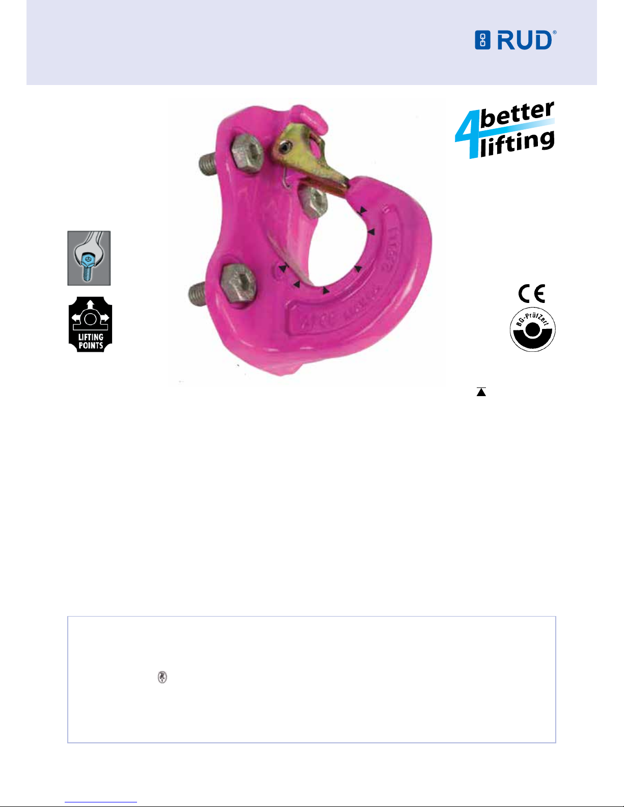
EXCAVATOR HOOK - VABH-B
1. Reference should be made to relevant standards and other
statutory regulations. Inspections should be carried out by
competent persons only.
2. Before installing and every use, visually inspect RUD lifting
points, with particular attention to any evidence of corrosion,
wear and weld cracks and deformations. Please ensure
compatibility of bolt thread and tapped hole.
3. The material construction to which the lifting point will be
attached, should be of adequate strength to withstand forces
during lifting without deformation. RUD, with reference to
the German testing authority BG, recommends the following
minimum for bolt lengths:
• 1.5 x M in steel (minimum quality S235JR [1.0037])
≈ AS3678 GR250.
• 1.5 x M in cast iron (for example GG 25)
• 2 x M in aluminium alloys
• 2.5 x M in aluminium-magnesium alloys
• ( M = diameter of RUD lifting point bolt, e.g. M 20 )
When lifting light metals, nonferrous heavy metals and
gray cast iron, the thread has to be chosen in such a way
that the working load limit of the thread corresponds to the
requirements of the respective base material.
RUD excavator hooks are delivered with 100% crack tested
bolts. When using your own bolts, the bolts have to be
100% crack tested. The min quality hexagon bolt has to be
10.9 accord. EN 24014 (DIN 931) with the nominal diameter.
4. The lifting points must be positioned on the load in such a
way that movement is avoided during lifting.
a) For single leg lifts, the lifting point should be vertically
above the centre of gravity of the load.
b) For two leg lifts, the lifting points must be equidistant to/or
above the centre of gravity of the load.
c) For three and four leg lifts, the lifting points should be
arranged symmetrically around the centre of gravity in the
same plane if possible.
The installation should be in the direction of pull (picture 1).
5. Load Symmetry: The working load limit of individual RUD
lifting points are calculated using the following formula and
are based on symmetrical loading:
NOTE: For WLL Calculations
• ß angle is taken from the vertical plane.
• Included angle is the angle between the sling legs.
6. Safety: When lifting points are used in a multileg assembly,
care should be taken to calculate the WLL (Working Load
Limit) due to the deration caused by forces acting in multiple
directions. The reduction in WLL (Working Load Limit)
for multileg assemblies should be checked with relevant
Standards e.g. AS 3775-2004 - Chain Slings-Gr t (8)
The lifting points should be mounted in such a way that
they may easily be accessed for inspection and assembly/
disassembly of the sling.
User Instructions - Part 2
7. A plane bolting surface must be guaranteed to ensure
correct mating of the lifting component.
8. The VABH-B should be tightened to torque according to
table 1 (+/- 10%).
9. All ttings connected to the VABH-B should be free moving.
When connecting and disconnecting the lifting means (wire
ropes, chain slings, round slings) pinches and impacts should
be avoided. Damage to lifting components caused by sharp
corners should also be avoided.
10. To prevent unintended dismounting through shock
loading, rotation or vibration, thread locking uid such as
Loctite (depending on the application, please refer to the
manufacturer’s instruction) should be used to secure the bolt.
11. If the lifting points are used exclusively for lashing,
the value of the working load can be doubled. LC (lashing
capacity) = 2 x WLL.
12. Effects of temperature: Due to the DIN/EN bolts that
are used with the VABH-B the working load limit should be
reduced accordingly:
-10° to 100°C no reduction 14°F to 212°F
100° to 200°C minus 15% 212°F to 392°F
200° to 250°C minus 20% 392°F to 482°F
250° to 350°C minus 25% 482°F to 662°F
Temperatures above 350°C (662°F) are not permitted.
13. RUD-Lifting points must not be used under chemical
inuences such as acids, alkaline solutions and vapours e.g.
in pickling baths or hot dip galvanising plants. If this cannot
be avoided, please contact the manufacturer indicating the
concentration, period of penetration and temperature of use.
14. After tting, an annual inspection or sooner if conditions
dictate should be undertaken by a competent person
examining the continued suitability. Also inspect after damage
and special occurrences.
Inspection criteria regarding paragraphs 2 and 14:
• Ensure correct bolt and nut size, quality and length.
• Ensure compatibility of bolt thread and tapped hole - control
of the torque
• The lifting point should be complete.
• The working load limit and manufacturers stamp should be
clearly visible.
• Deformation of the component parts such as body, load
ring and bolt.
• Mechanical damage, such as notches, particularly in high
stress areas.
• Wear should be no more than 10% (see wear indicators for
measuring).
• Evidence of corrosion.
• Evidence of cracks.
• The excavator hook has to be mounted on plane bolting
surfaces with the full back side.
• Opening of the mouth is deformed no more than 10%.
• Damage to the bolt, nut and/or thread.
Any non-adherence to this advice may result in damages
of persons and/or materials!
WLL = required of lifting point/individual leg (kg)
G = load weight (kg)
n = number of load bearing legs
ß = angle of inclination of the individual leg
WLL = G
n x cos ß