Olympus Focus PX User manual

FOCUS PX — Getting Started Guide 1
Intended Use
The FOCUS PX phased array and conventional ultrasonic data acquisition instrument is designed to
perform nondestructive inspections of industrial and commercial materials. Do not use the FOCUS PX
for any purpose other than its intended use.
Instruction Manual
Before use, thoroughly review the FOCUS PX User’s Manual. Use the product as instructed. The User’s
Manual contains essential information on how to use this Olympus product safely and effectively.
Keep the User’s Manual in a safe, accessible location.
Safety Signal Words
Indicates an imminently hazardous situation and calls attention to a procedure, practice, or the like,
which, if not correctly performed or adhered to, will result in death or serious personal injury.
Indicates a potentially hazardous situation and calls attention to a procedure, practice, or the like,
which, if not correctly performed or adhered to, could result in death or serious personal injury.
Indicates a potentially hazardous situation and calls attention to a procedure, practice, or the like,
which, if not correctly performed or adhered to, may result in minor or moderate personal injury,
material damage, particularly to the product, destruction of part or all of the product, or loss of data.
DANGER
WARNING
CAUTION
FOCUS PX
Getting Started Guide

2 FOCUS PX — Getting Started Guide
Package Contents
The FOCUS PX comes standard with several key accessories:
• Transport case
• DC power adaptor (power supply)
• Power cord (model varies according to country)
• USB flash drive, which contains:
—FocusPCsoftware
—Calculatorsoftware
— FocusPC Viewer
— FocusControl software development kit
— FocusData software development kit
—FocusPC UT and Phased Array Data Acquisition and Analysis Software User’s Manual
—FocusPC UT and Phased Array Data Acquisition and Analysis Software Advanced User’s Manual
—FOCUS PX Getting Started Guide
—FOCUS PX Phased Array and Conventional Ultrasonic Data Acquisition Instrument User’s
Manual
• Crossover Ethernet cable (category 5e or higher) [5 m] (16.4 ft)
• Screwdriver for bumper removal
• Digital input cable (5 m) [16.4 ft]
• Digital output cable (5 m) [16.4 ft]
• Calibration certificate
Make sure that the contents of the package are complete before using the FOCUS PX. If any items are
missing or damaged, contact Olympus.
Connections
To reduce the risk of electric shock, avoid touching the inner conductor of the connectors. Up to 200 V
can be present on the inner conductor of the UT connectors, and up to 115 V can be present on the PA
connector.
Figure 1 on page 3 shows the FOCUS PX front panel, which enables you to do the following:
• Connect a PA probe (or multiple PA and UT probes using a splitter)
• Connect the power earth connection to an appropriate cable or lug in a cabinet or on a suitable
grounded structure
• Connect up to 8 conventional UT probes
• Turn on and off the FOCUS PX
• Get the FOCUS PX status using the indicators

FOCUS PX — Getting Started Guide 3
Figure 1 The FOCUS PX front panel
Figure 2 on page 4 shows the FOCUS PX rear panel, which enables you to do the following:
• Connect a scanner
• Connect input and output signals (encoders, alarms, etc.)
• Connect the FOCUS PX to an Ethernet network
• Connect the FOCUS PX to a table top power supply
• Connect the FOCUS PX to a suitable power source
• Synchronize multiple FOCUS PX
A suitable power source is a dedicated safety extra low voltage (SELV) limited power source (LPS) in
the range of 10 VDC to 24 VDC for the primary power source, and in the range of 15 VDC to 18 VDC
for the auxiliary power source.
Phased array connector Indicators Power switch
UT connectors

4 FOCUS PX — Getting Started Guide
Figure 2 The FOCUS PX rear panel
For more details about the FOCUS PX connectors, indicators, and switch, refer to the FOCUS PX
Phased Array and Conventional Ultrasonic Data Acquisition Instrument User’s Manual.
To Install a FOCUS PX
1. Install the FOCUS PX away from heat sources, leaving a minimum clearance of 5 cm (2 in.) on
each side to allow heat dissipation.
To prevent water infiltration, use waterproof cables. Water infiltration could damage the FOCUS PX.
2. Using a category 5e Ethernet crossover cable, connect the FOCUS PX Ethernet connector to the
network interface card of the inspection computer. The cable supplied with the FOCUS PX is a
category 5e Ethernet crossover cable (Olympus part no. 60ND0001).
When using the FOCUS PX in harsh environments, select an Ethernet cable that has a high resistance
to friction, tensile stress, and torsion.
3. Install FocusPC on the inspection computer, and then follow the wizard steps to configure the
network card for connection to the FOCUS PX.
Primary DC input
connector
Ethernet connector
Auxiliary DC input connector
I/O connector
SYNCH. IN and SYNCH. OUT
connectors
DIG. OUT ALARMS
connector

FOCUS PX — Getting Started Guide 5
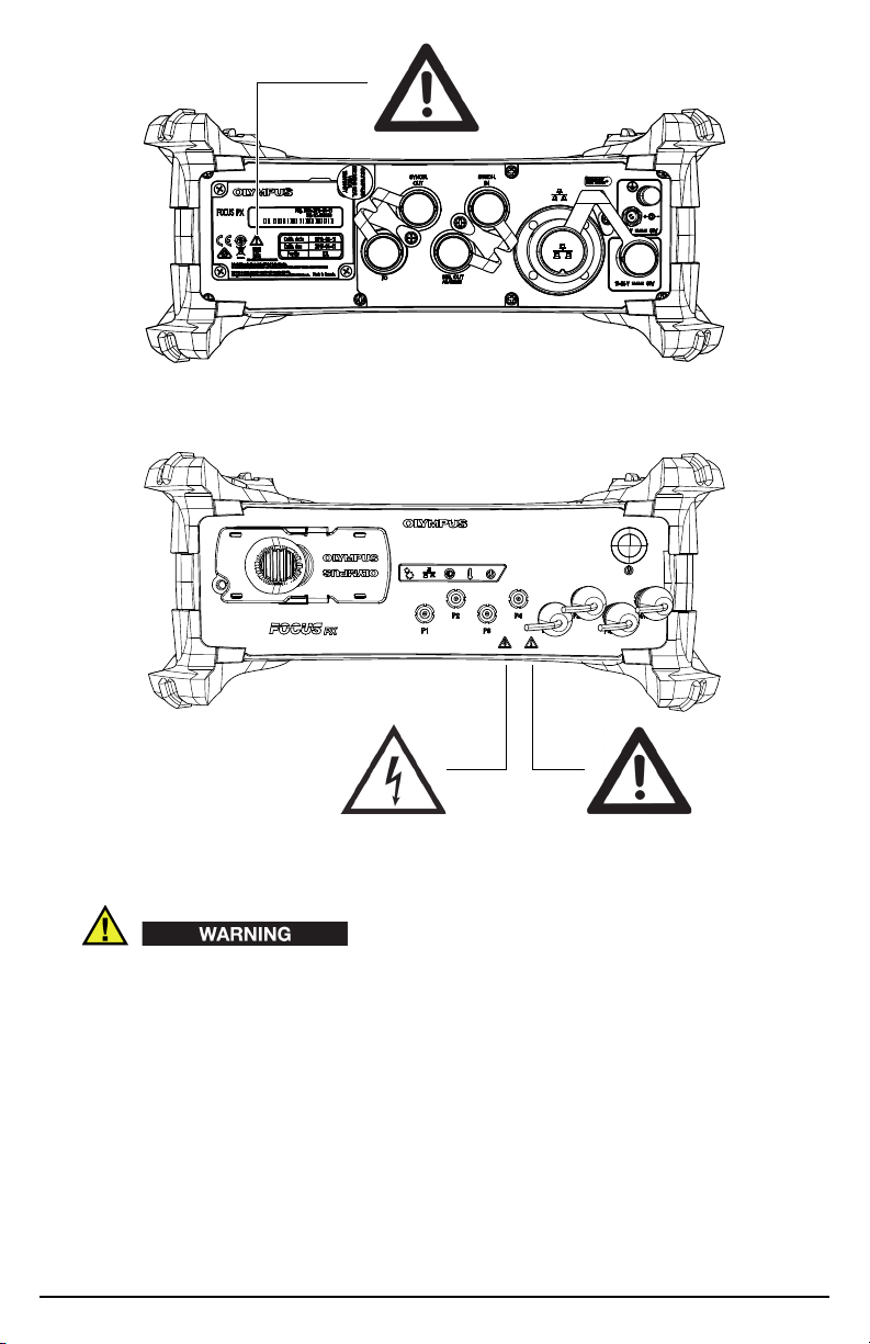
To prevent the risk of an electric shock, Olympus strongly recommends turning off the FOCUS PX
before connecting and disconnecting the probes.
Probes can suffer permanent damage if fired without couplant. If the probes are not being used for
inspection, the FOCUS PX should be turned off.
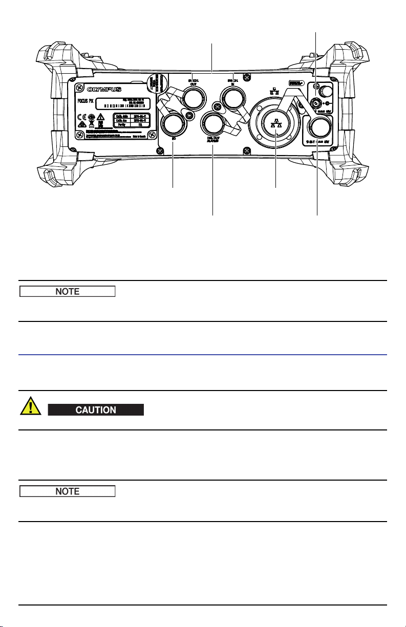
4. Using the appropriate cables, connect the probes to the phased array connector and/or to the UT
connectors.
5. Using the appropriate cables, connect each of the components required by your setup and your
needs to the corresponding FOCUS PX connectors (for example, encoders, alarms, etc.).
For all the details on the connectors, refer to the FOCUS PX Phased Array and Conventional Ultrasonic
Data Acquisition Instrument User’s Manual.
6. Connect the DC power adaptor to the FOCUS PX instrument’s DC input connector. Connect the
other end of the power cord to a suitable power source.
7. Turn on the FOCUS PX by pressing the power switch.
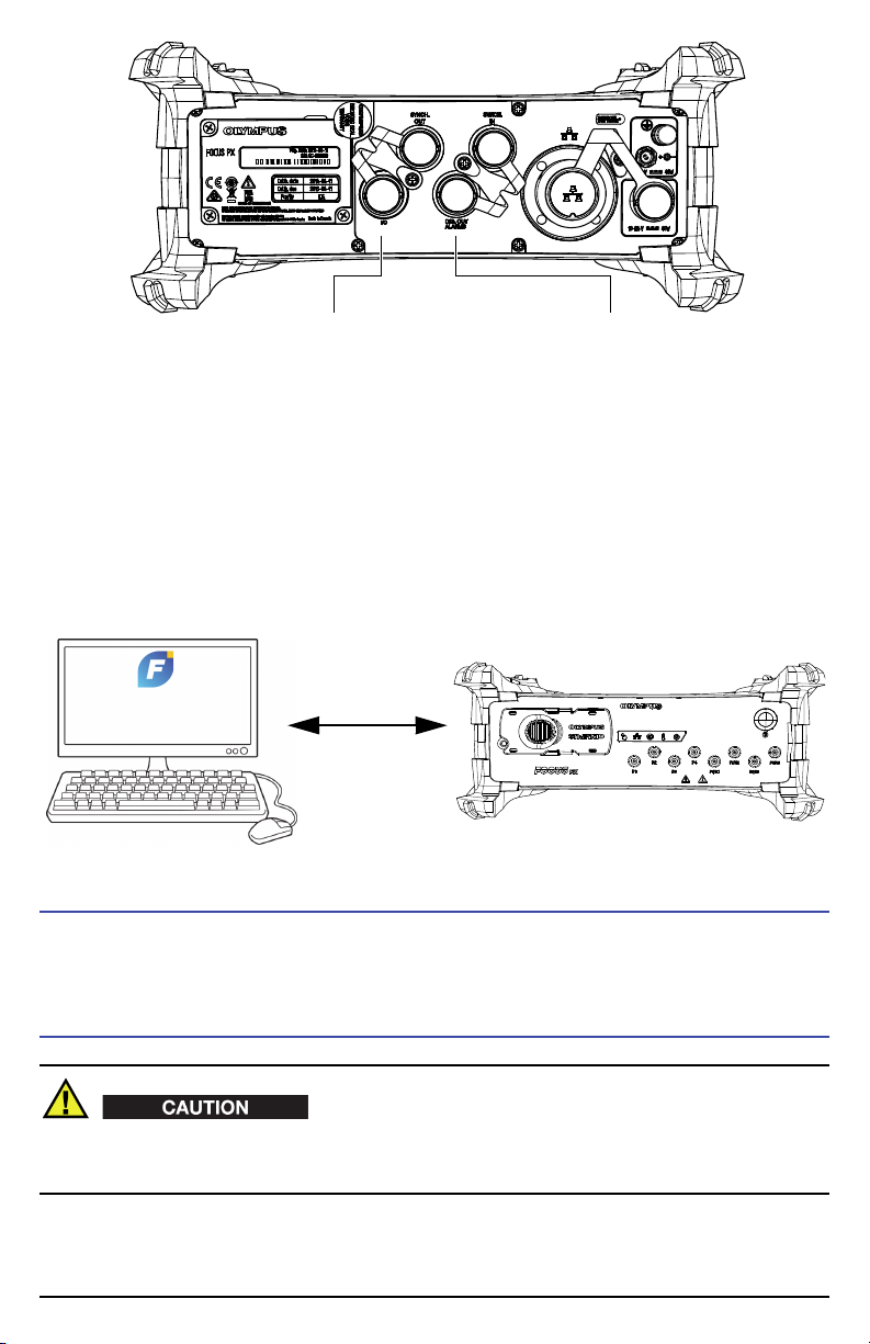
To Connect Multiple FOCUS PX Instruments to a Computer
When three or more FOCUS PX instruments are stacked on top of each other, they must be supported
by a rack or an appropriate mechanical device. If no such support is used, the assembly is unstable and
may fall over, which could cause human injury or equipment damage.
1. Using category 5e Ethernet crossover cables, connect each FOCUS PX Ethernet connector to an
input port of a gigabit Ethernet switch, and then connect the switch to the inspection computer.
When using FOCUS PX instruments in harsh environments, select Ethernet cables that have a high
resistance to friction, tensile stress, and torsion.
2. Turn on each FOCUS PX.
Automatic Start-Up Mode
The FOCUS PX has an automatic start-up mode (auto-boot) that can be used to remotely start the
FOCUS PX. When this mode is enabled, you do not need to press the power switch to start the
FOCUS PX. When this mode is enabled, the FOCUS PX starts up automatically when connected to the
DC power adaptor. This mode is disabled by default.

6 FOCUS PX — Getting Started Guide
To activate the auto-boot
1. Turn off the FOCUS PX, and then disconnect the DC power adaptor.
2. While pressing the power switch, connect the FOCUS PX to the DC power adaptor.
3. Wait for 5 to 10 seconds, and then release the power switch.
The power indicator light will blink two times.
4. To deactivate the auto-boot, repeat steps 1 to 3.
Indicators
Figure 3 on page 6 shows the FOCUS PX front panel indicators.
Figure 3 The FOCUS PX indicators
Mechanical indicator ( )
This indicator is reserved for future use.
Ethernet indicator ( )
When this indicator lights up green or orange, it indicates that the Ethernet link is
established.
When this indicator flashes green or orange, it indicates there is activity on the Ethernet link.
A green indicator corresponds to a 1000 megabits per second (Mbps) Ethernet connection,
while an orange indicator corresponds to a 100 Mbps connection.
Power supply status indicator ( )
When this indicator lights up green, it indicates that the instrument is powered by direct
current through the DC power adaptor (primary DC input connector).
When this indicator lights up red, it indicates that the primary DC power supply is outside
the 10 VDC to 24 VDC range. If the input voltage is found to be outside the allowable limits,
contact the After-Sales Service.
When this indicator is turned off, it indicates that no power is available.
Temperature indicator ( )
When this indicator lights up green, it indicates that the internal temperature is within the
operating temperature range.
When the indicator lights up red, it indicates that the internal temperature is above the
upper limit. The FOCUS PX will automatically shut down. You must wait for the FOCUS PX
to cool down before turning it back on.
Power indicator ( )
When this indicator lights up green, it indicates that the FOCUS PX is turned on.

FOCUS PX — Getting Started Guide 7
When this indicator flashes green, it indicates that the FOCUS PX is either starting up or
shutting down.
When this indicator flashes red three times after the power button has been pressed, it
indicates that the FOCUS PX instrument’s internal temperature is above the upper
temperature limit. Wait for the FOCUS PX to cool down.
When this indicator flashes red continuously, it indicates that the FOCUS PX is in safe mode
(flash memory error). Contact the After-Sales Service.
Integrating the FOCUS PX in an Automated System
The FOCUS PX was designed with flexible programmable logic controller (PLC) and software
integration features to enable easy integration into automated inspection systems (see Figure 4 on
page 7).
Figure 4 Example of a fully automated inspection system1
For PLC and scanner integration, the connectors on the rear panel enable the FOCUS PX to be
interfaced with a PLC or a scanner to exchange the following commands (refer to the FOCUS PX
Phased Array and Conventional Ultrasonic Data Acquisition Instrument User’s Manual for more details):
1. Photo courtesy of SCLEAD.

8 FOCUS PX — Getting Started Guide
For software integration, the flexibility of FocusPC, FocusControl, and FocusData enables the creation
of fully customized applications designed to precisely match your inspection requirements (refer to
the FocusPC UT and Phased Array Data Acquisition and Analysis Software User’s Manual for more details).
Equipment Disposal
Before disposing of the FOCUS PX, contact your local Olympus distributor for disposal information
and instructions.
Electrical Warnings
To avoid the risk of electric shock, do not touch the inner conductor of the connectors. Up to 200 V can
be present on the inner conductor of the UT connectors, and up to 115 V can be present on the PA
connector.
Start/stop inspection
Start/stop firing
Receive top turn signal
Reset encoder signal
Receive encoder signal
Connect a scanner
Supply power to an external device
Monitor alarms
Customized application

FOCUS PX — Getting Started Guide 9
Figure 5 Warning symbol on rear panel
Figure 6 Warning symbols on front panel
• Before operating this instrument using mains electricity, you must connect the protective earth
terminal of the instrument to the protective conductor (mains) of the power cord. The mains plug
shall only be inserted into a socket outlet provided with a protective earth contact. Never negate
the protective action by using an extension cord (power cable) without a protective conductor
(grounding).
• If there is any possibility that the ground protection could be impaired, you must make the
instrument inoperative and secure it against any unintended operation.
• The instrument must only be connected to a power source corresponding to the type indicated on
the rating label.


Olympus Scientific Solutions Americas, 48 Woerd Avenue, Waltham,
MA 02453, USA
www.olympus-ims.com
Printed in Canada • Copyright © 2015 by Olympus. All rights reserved.
All brands are trademarks or registered trademarks of their respective owners and third party entities.
Part ID: U8148078 *U8148078* Printed on Rolland Hitech50,
which contains 50 % post-
consumer fiber.
DMTA-20079-01EN
Rev. B, June 2015 *DMTA-20079-01EN*
50%
FOCUS PX — Getting Started Guide
Table of contents