r
TABLE
OF
CONTENT
S
Page
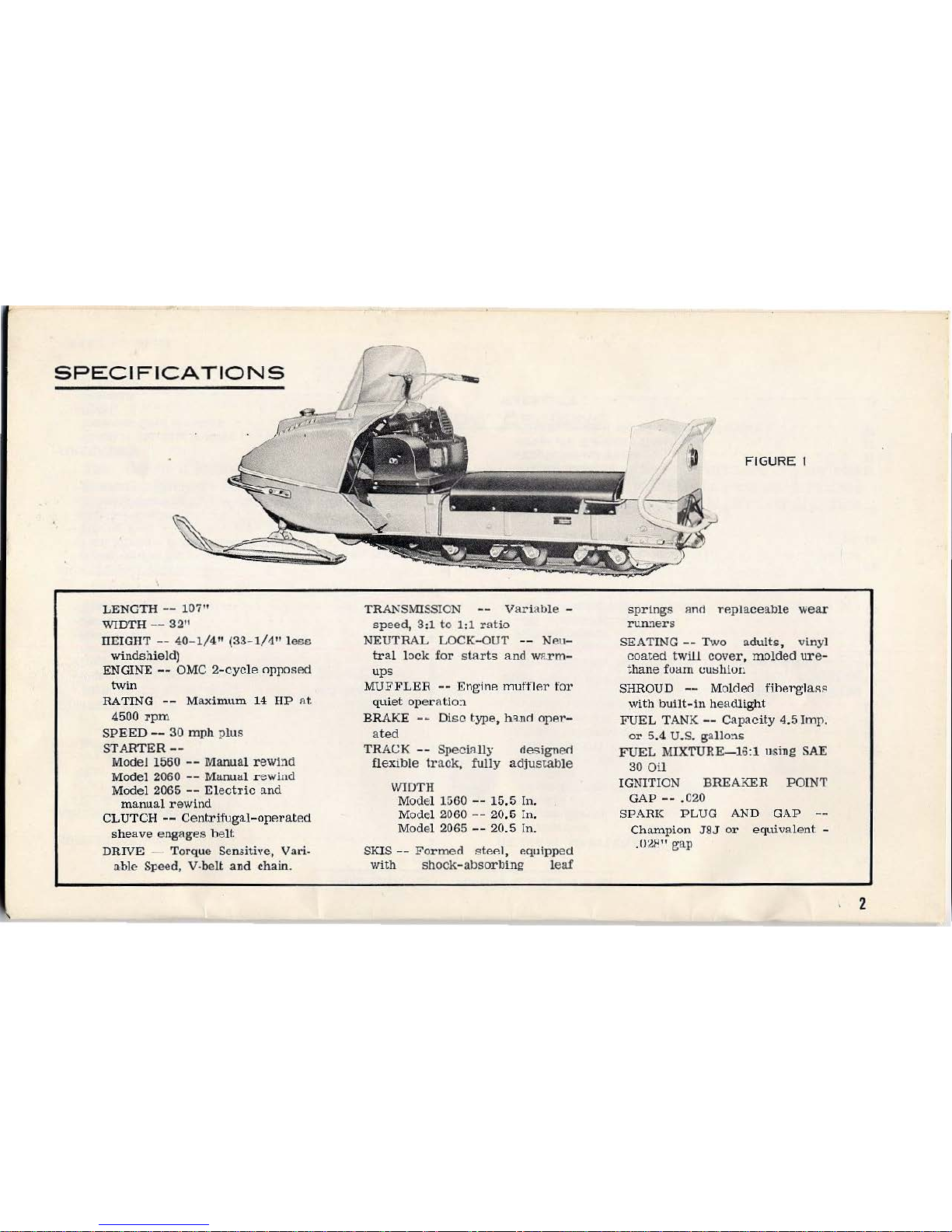
SPEC
IFICATIONS • • • • • • • . . . . • • • • . • • . • 2
ASSEMBLY
INSTRUCTIONS
-W
i
ndsh
i
eld
• • • • • • • • • • . • • • • 3
-Taillight
• • • • • • • • • • • . . • • • 3
-:::>kis
• • • • • • • • • . . • • . • • . • 3
-Tow Ba:r,
Seat
Dack &
Compar
t
mcn
,t : • 3
-Battery.
• • • • • . • • • . • • . • . • 3
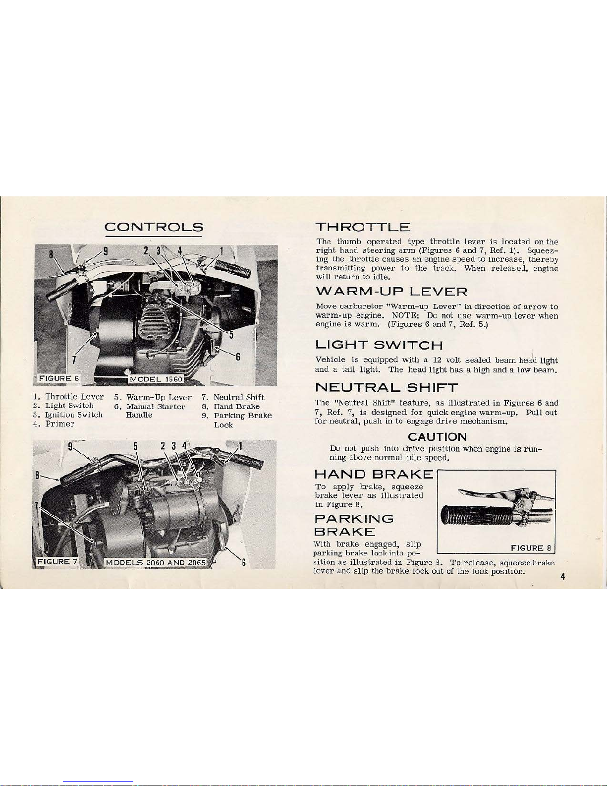
CONTROLS
-Throttle
• • • • • 4
-Warm
-U
p
Lever.
1
-Ligh
t
Swi
t
ch
• • 4
-Neutral
Shift
• • 4
-Hand
Hrake
• • 4
-Po.rking
Brllltc
• 4
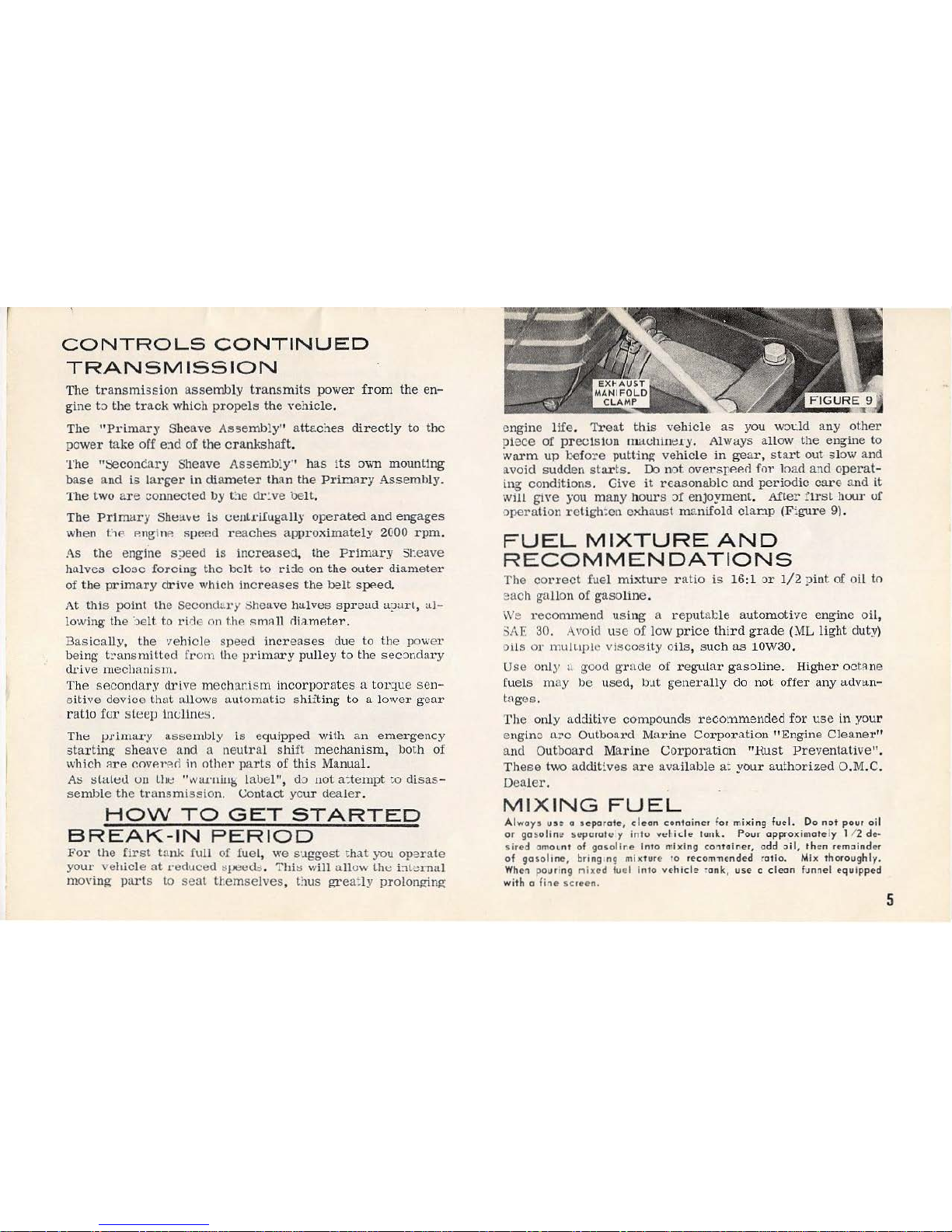
-
Transmission
• 5
HOW
TO
GR'T'
STARTED
-B1·eak-In Pel'iod . . . . • . . . , • G
-
Fuel
Mixture
& Recommendations
!'i
-Mix
i
ng
Fuel
• . . • 5
-Start
ing
Engine
. . 6
-Electric
SL<u·
C
ing
7
-Emergency
St
arting
7
OP
ERAT
I
ON
- E
lectric
Starting
Models 7
-Extreme
Cold
Weather
7
-Uph!ll
• • . . • • • 7
-Downhill
. • • . • • 7
-Glare
Ice
. • . . . 7
-Safety
Precautions
8
PART
No.
404278
GENE
R
AL
MAINTENANCE
-Ca
.
rhuretor
-
Engine
Shroud
••
•••
.
-
Battery
.•.....
..
. .
-Chain
&
Transmissio
n
Guard
-Gas
Tank
.......•
-Dl'ive
Cha
in
Adjustment
•
-
Install
i
ng
Drive
Chain
.
-Brake
Adj
us
tment
-T
rack
Tension
-Traek
AligrunenL
D
RIVE
BELT
REPLACEMENT
••••.
•
••••
-Procedure
for
Installing
the
Transmission
Belt
-::>tarter Motor Drive Belt • •
-Ski
Alignment
• • • • • • • •
-Off
Season
Storage
• • • . .
-After
Storing
-
Before
Using
TROTJRT.F.
CH
ECK
L
IST
SERVIC
E DIAGNOSIS • •
MAINTENANCE
AND
LUBRIC
AT
IOK
ITEMS
OF
SPECIAL
INTEREST
-Repair
Service
•••••••
-Replacement
Parts
. . . . .
-Owner':;
Warranty
Certificate
•
-Where
to
Find
Model
&
Serial
Ntunber
WARRAN
TY
...••.•.•
• . •
.•
••
Page
8
9
9
9
9
9
10
10
11
11
12
13
13
11
14
14
14
15-16
16
17
17
17
17
...
..
~ 18