Opus Technologies OCTOPUS Multi-Room User manual

Octopus
Multi-Room
Entertainment System
User Guide
by Opus Technologies

Important safety warnings and precautions are included within the Installation Guide supplied with this system. Please
ensure you read these. If you do not have a copy of this guide please ask you installer or dealer or download a copy at:
www.opus-ttechnologies.co.uk
2

Component overview
Master control unit
(MCU300)
Central control unit, which connects to your audio/visual
sources and distributes them to the desired zone
AMR650
Active and passive A-BUSTM compatible
ceiling mounted speaker pair
Wall control unit
(WCU310)
Keypad used to select and control
sources connected to the MCU
Video switching unit
(VSU300)
Distributes visual sources to zone
screens (optional)
System remote control
(SRC300)
System remote control for everday use
in conjunction with the keypad
Learning remote control
(LRC300)
Learning remote for controlling source
equipment and teaching infra-red
source commands to the MCU (see
dedicated manual for operation)
3

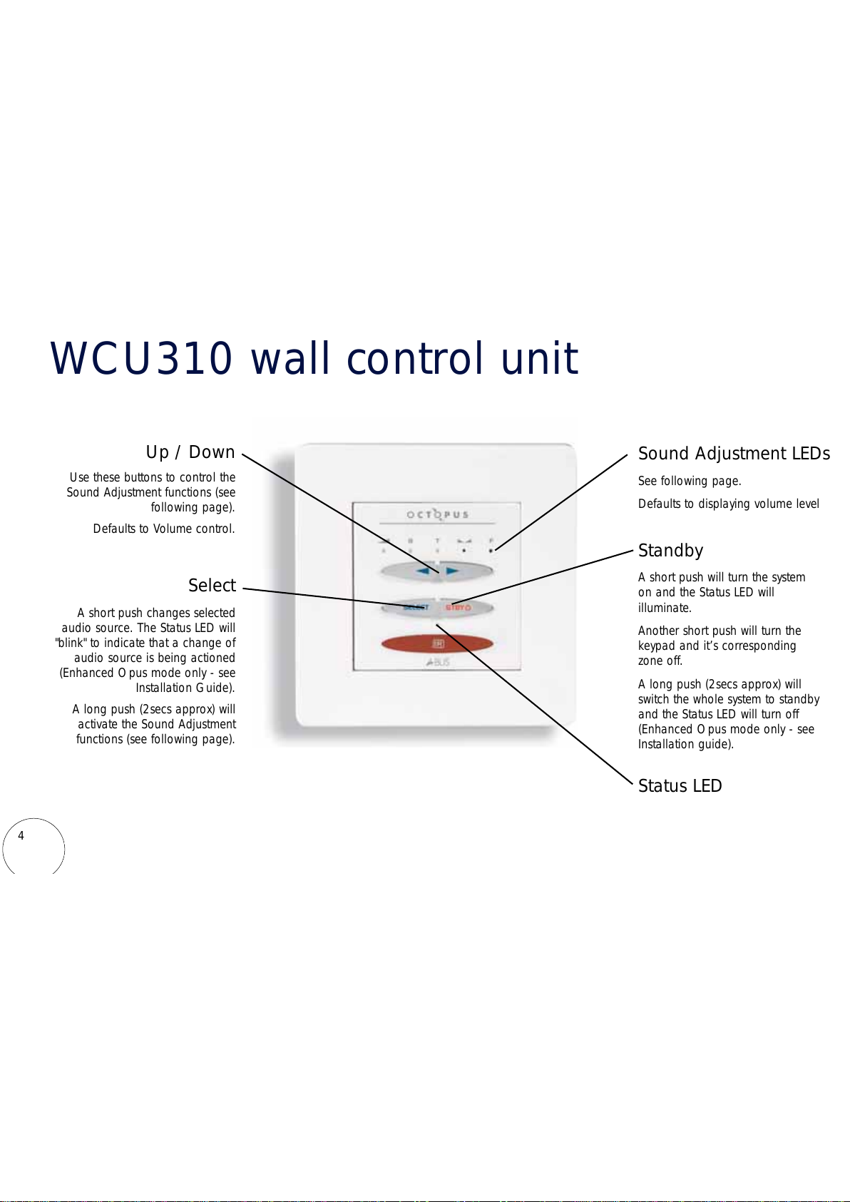
WCU310 wall control unit
Standby
A short push will turn the system
on and the Status LED will
illuminate.
Another short push will turn the
keypad and it’s corresponding
zone off.
A long push (2secs approx) will
switch the whole system to standby
and the Status LED will turn off
(Enhanced Opus mode only - see
Installation guide).
Select
A short push changes selected
audio source. The Status LED will
"blink" to indicate that a change of
audio source is being actioned
(Enhanced Opus mode only - see
Installation Guide).
A long push (2secs approx) will
activate the Sound Adjustment
functions (see following page).
Up / Down
Use these buttons to control the
Sound Adjustment functions (see
following page).
Defaults to Volume control.
Sound Adjustment LEDs
See following page.
Defaults to displaying volume level
Status LED
4

Continue to hold Select
Release when Bass LED is lit
Adjust Bass level using Up/Down
buttons
Keypad sound adjustment functions
The Up / Down buttons are used to adjust Volume. To access the other sound adjustment
functions below press and hold the Select button for approx two seconds:
Continue to hold Select
Release when Treble LED is lit
Adjust Treble level using
Up/Down buttons
Continue to hold Select
Release when Balance LED is lit
Adjust Balance using Up/Down
buttons
Continue to hold Select
Release when Fader LED is lit
Adjust audio levels between main
speakers, and any extra
equipment connected to the
WCU pre-amp output. Not
applicable to all installations.
Note: If no action is taken for approximately two seconds
the sound adjustment function will default to volume control
Bass Treble Balance Fader
5

One bleep will sound
Adjust Bass level using
volume buttons
Sound adjustment functions
Two bleeps will sound
Adjust Treble level using
volume buttons
Three bleeps will sound
Adjust Balance using volume
buttons (Up=Towards right,
Down=Towards left)
Four bleeps will sound
Adjust audio levels between
main speakers, and any extra
equipment connected to the
AMR650 pre-amp output
(Up=Towards main,
Down=Towards preamp)
During
sound
adjustment
tones
are
generated
to
indicate
postion
within
the
available
range:
A single medium frequency tone indicate a neutral setting.
Two rising tones indicate the upper level of adjustment has been reached.
Two falling tones indicate the lower level of adjustment range has been reached.
Press Select Press Select Press Select
For Active speaker only (AMR650) – Press the Select button
Bass Treble Balance Fader
(if applicable)
6

7
SRC300 system remote control
Standby
Turns the keypad and it’s corresponding
zone on and off
Source select
Selects source to be listened to
Local
Selects local input where fitted
EXT/CCTV
Selects additional source (eg CCTV) if fitted
All off
Switches the whole system to Standby
Mute
Mutes the audio output of the system
Select
See previous section
Volume
See previous section

8
Adding your source equipment
Diagram shows audio
source equipment
connections
Phono-Phono/RCA-RCA
hi-fi interconnect cable
Opus IR-1
AAUUDDIIOO
CCOONNNNEECCTTIIOONNSS
Audio Source Equipment Connections
Up to six pieces of audio source equipment can be connected to an MCU. Connections are made from the source equipments’
audio outputs to the inputs on the MCU via RCA connections.
Remote control of source equipment through the WCU310
For remote control of the source equipment, 6 routed IR outputs are provided. Individual IR emitters are plugged into the appropriate
IR output (corresponding to the respective Audio input) the other end is stuck to the IR receiving window of the source equipment.

9
FAQs
1. What entertainment equipment can I connect?
The Octopus system is compatible with almost any type of hi-fi or video separate.
2. What is the difference between a main zone and a sub-zone?
A sub-zone can only listen to the same audio source as is being listened to in the main zone. The sub-zone has
independent power, volume and tone controls from the main zone.
3. How many rooms can a system serve?
Each MCU300 supports 4 main + 4 sub-zones. 4 MCU's can be chained together supporting up to a maximum of 16
main zones and 16 sub-zones. If a larger system is required it is possible to have two or more separate systems
running independently giving unlimited expandability.
4. Can I use any Cat5e cable or must I use the orange Octopus
Cat5e cable?
Any type of Cat5e can be used.

10
5. Do I have to use Octopus speakers?
No, but it is highly recommended as the Octopus speakers are optimised and impedance matched to the
keypad amplifiers.
6. How many remote controls can the system have?
There is no limit to the amount of remotes you can have. If required you can have a remote in each room.
7. What advice can you give for keypad location?
When locating a keypad you should avoid putting in direct sunlight or in close proximity to Plasma screens.
Care should also be taken locating it near to devices that produce electrical noise such as mechanical dimmers.
8. Is there a maximum cable run from MCU to each WCU?
Yes, the maximum cable run is 30 metres / 100 feet.

System details
1
2
3
4
5
6
7
8
9
10
11
12
13
14
15
16
Zone/room details Sub zones
9
Source equipment details
(Insert name of equipment connected to this input)
Tuner (1)
CD (2)
DVD (3)
Source (4)
Source (5)
Source (6)
Installer Details
Name / address
Tel No.
Email
Contact name
MCU Serial No/s.
11

www.opus-technologies.co.uk/octopus
Made from Recyclable material
Part Number AP15687/3
Octopus is a trademark of Opus Technologies UK LLP. All rights reserved.
A-BUStm is a registered trademark of LeisureTech Electronics PTY Ltd Australia.
Opus Technologies is a member of the Custom Electronic design & Installation Association.
Table of contents
Other Opus Technologies Home Theater System manuals