Original inside CAT NOVA 3100 T ED User manual

/PERATOR@S MANUAL
GB
).3425#4)/.3 &/2 02/$5#4 $%,)6%29 0AGE
4RANSLATION OF THE ORIGINAL /PERATING -ANUAL
Ihre / Your / Votre • Masch.Nr. • Fgst.Ident.Nr.
.R
CAT NOVA 3100 T ED
(Type PSM 3531 : +..01001)
99 3531.GB.80I.0
Disc mower

ALLG./BA SEITE 2 / 0000-GB
Important information concerning Product
Liability.
According to the laws governing product liability, the manufacturer and dealer are obliged to hand the
operating manual to the customer at the time of sale, and to instruct them in the recommended operating,
safety, and maintenance regulations. Confirmation is necessary to prove that the machine and operating
manual have been handed over accordingly.
For this purpose,
- document A is to be signed and sent to Pöttinger,
- document B remains with the dealer supplying the machine,
- and the customer receives document C.
In accordance with the laws of product liability, every farmer is an entrepreneur.
According to the laws of product liability, property damage is damage caused by a machine and not to
it. An excess of Euro 500 is provided for such a liabilioty.
In accordance with the laws of product liability, entrepreneurial property damages are excluded from
the liability.
Attention! Should the customer resell the machine at a later date, the operating manual must be given
to the new owner who must then be instructed in the recommended regulations referred to herein.
GB Dear Farmer
You have just made an excellent choice. Naturally we are very happy
and wish to congratulate you for having chosen Pöttinger. As your
agricultural partner, we offer you quality and efficiency combined with
reliable servicing.
In order to assess the spare-parts demand for our agricultural machines
and to take these demands into consideration when developing new
machines, we would ask you to provide us with some details.
Furthermore, we will also be able to inform you of new developments.

Dokument D
GB-0600 Dokum D Anbaugeräte
PÖTTINGER Landtechnik GmbH
Industriegelände 1
A-4710 Grieskirchen
Tel. 07248 / 600 -0
Telefax 07248 / 600-2511
TMachine checked according to delivery note. All attached parts removed. All safety equipment, drive shaft and operating
devices at hand.
TOperation and maintenance of machine and/or implement according to operating instructions explained to the customer.
TTyres checked re. correct pressure.
TWheel nuts checked re. tightness.
TDrive shaft cut to correct lenght.
T*VYYLJ[WV^LY[HRLVɈZWLLKPUKPJH[LK
TFitting to tractor carried out: to three-point linkage
TTrial run carried out and no defects found.
TFunctions explained during trial run.
TPivoting in transporting and operating position explained.
TInformation given re. optional extras.
TAbsolute need to read the operating manual indicated.
Please check. X
According to the product liability please check the above mentioned items.
INSTRUCTIONS FOR
PRODUCT DELIVERY
GB
In order to prove that the machine and the operating manual have been properly delivered, a confirmation is necessary.
For this purpose please do the following:
- sign the document A and send it to the company Pöttinger or via the internet to www.poettinger.at
- document B stays with the specialist factory delivering the machine.
- document C stays with the customer.

- 4 -
GB
0800_GB-Inhalt_3531
TABLE OF CONTENTS
Attention!
ÈÛìÞëïÞÌÚßÞíò
ÁâçíìâçíáÞ
ìîééåÞæÞçí
ÍÚÛåÞèßÜèçíÞçíì
WARNING SIGNS
CE sign ............................................................................................................................................................................. 5
Meanings of warning signs............................................................................................................................................... 5
ATTACHMENT
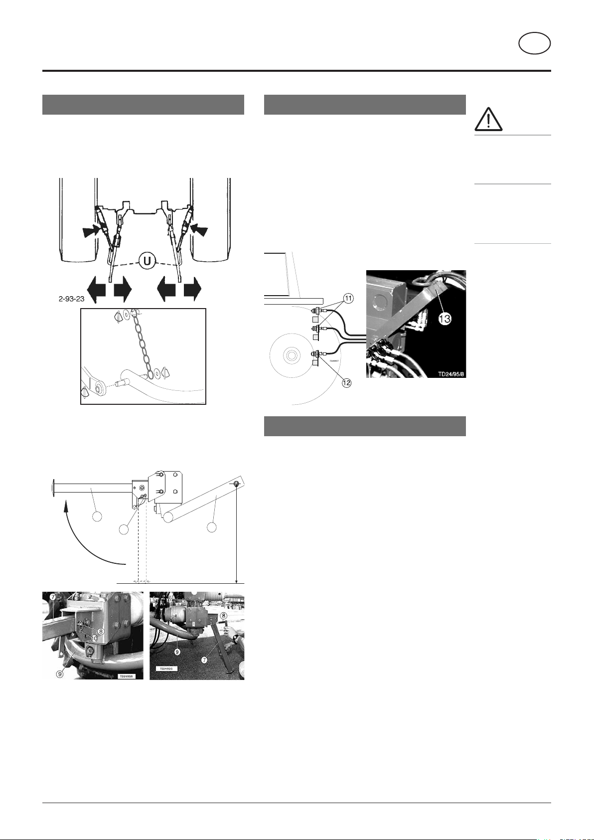
Attaching the machine ..................................................................................................................................................... 6
Connecting the hydraulics................................................................................................................................................ 6
Connecting the electrics................................................................................................................................................... 6
Check driving motor speed ............................................................................................................................................. 7
Correct drive shaft............................................................................................................................................................ 7
Drive shaft length ............................................................................................................................................................. 7
TRANSPORT AND WORKING POSITION
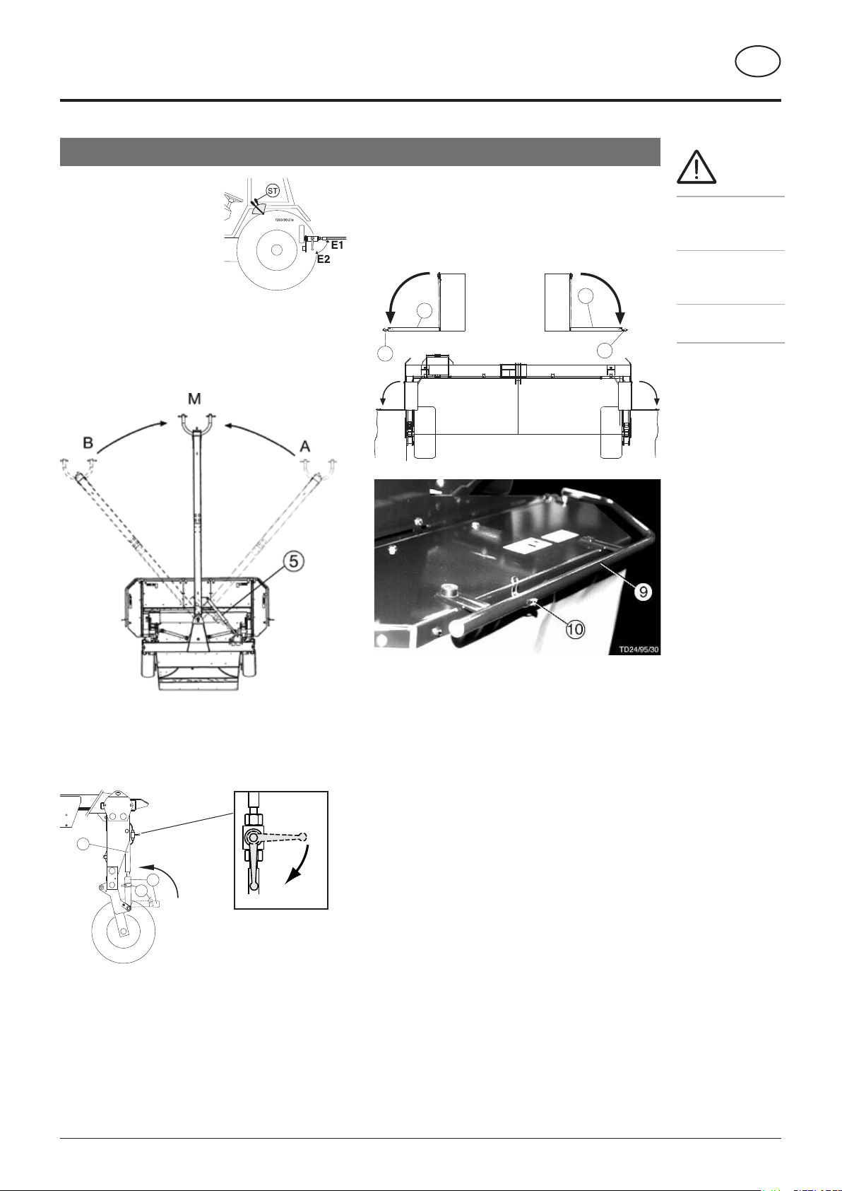
Conversion from transport to working position................................................................................................................ 8
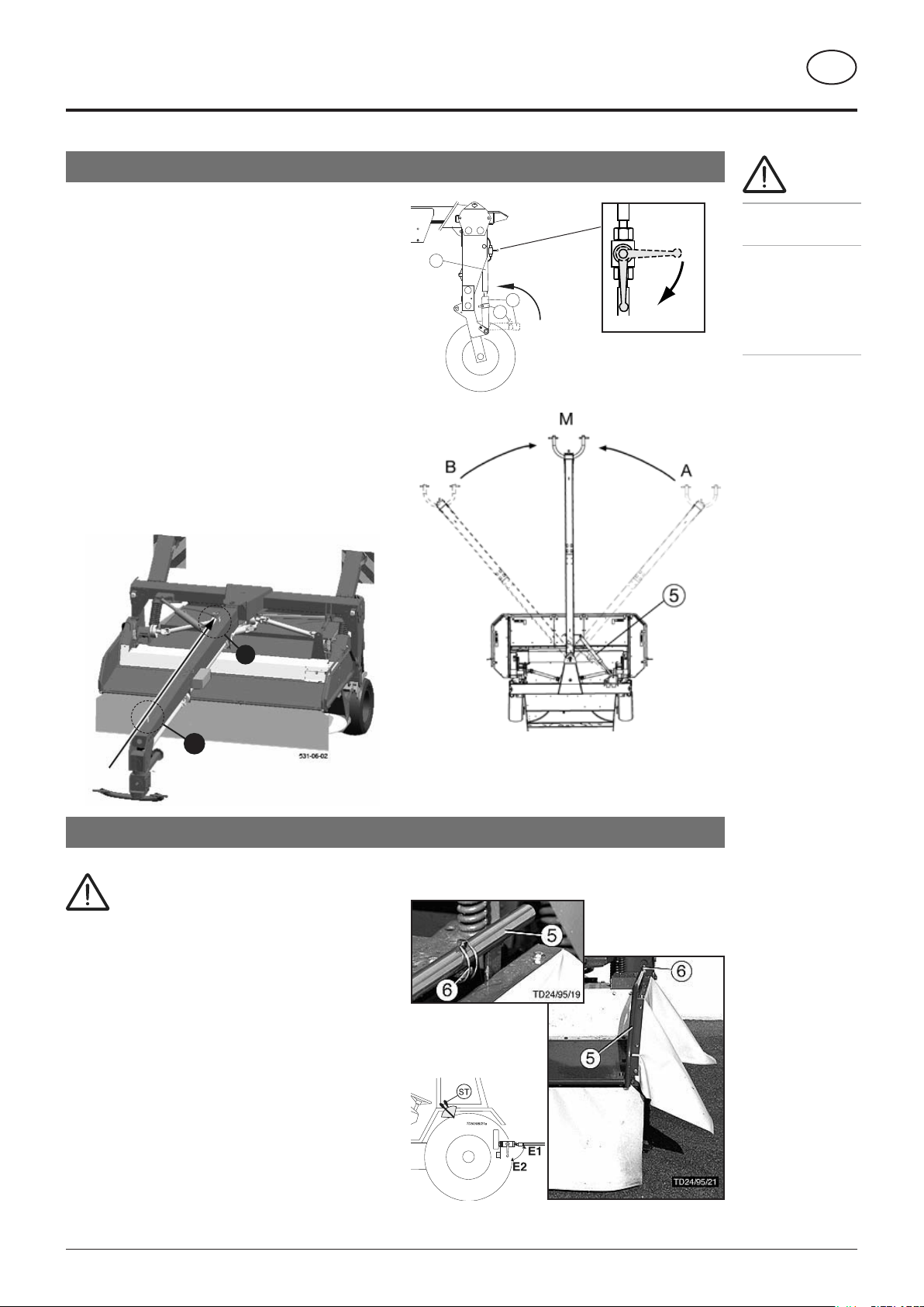
Changing from work to transport position ....................................................................................................................... 9
Transporting on public roads............................................................................................................................................ 9
OPERATION
Important points before starting work............................................................................................................................ 10
Adjustbearing pressure .................................................................................................................................................. 11
Adjusting cutting height.................................................................................................................................................. 12
Altering rotor rpm ........................................................................................................................................................... 12
Adjust cutting height with runner .................................................................................................................................. 12
Adjusting processor angle.............................................................................................................................................. 12
Adjusting swath width .................................................................................................................................................... 13
Long swath board .......................................................................................................................................................... 13
Swath formation to the side ........................................................................................................................................... 14
Electrohydraulic operation.............................................................................................................................................. 14
Variation "Extra dry" system........................................................................................................................................... 15
Dismounting the machine............................................................................................................................................... 16
CROSS CONVEYOR
Description ..................................................................................................................................................................... 17
Road transport ............................................................................................................................................................... 17
Settings .......................................................................................................................................................................... 17
Additional cross belt....................................................................................................................................................... 18
Road transport ............................................................................................................................................................... 18
Cleaning the Rollers ....................................................................................................................................................... 18
Adjusting the conveyor belt............................................................................................................................................ 18
MAINTENANCE
Safety point .................................................................................................................................................................... 19
General maintenance hints............................................................................................................................................. 19
Cleaning of machine parts ............................................................................................................................................. 19
Parking in the ope .......................................................................................................................................................... 19
Winter storage ................................................................................................................................................................ 19
Drive shafts..................................................................................................................................................................... 19
Hydraulic unit ................................................................................................................................................................. 19
After the first hours of operation .................................................................................................................................... 20
Roller-type conditioner ................................................................................................................................................... 20
Every 50 hours of operation ........................................................................................................................................... 21
Cutter bar-oil change...................................................................................................................................................... 21
Gearing........................................................................................................................................................................... 22
Starting transmission...................................................................................................................................................... 22
Garaging......................................................................................................................................................................... 23
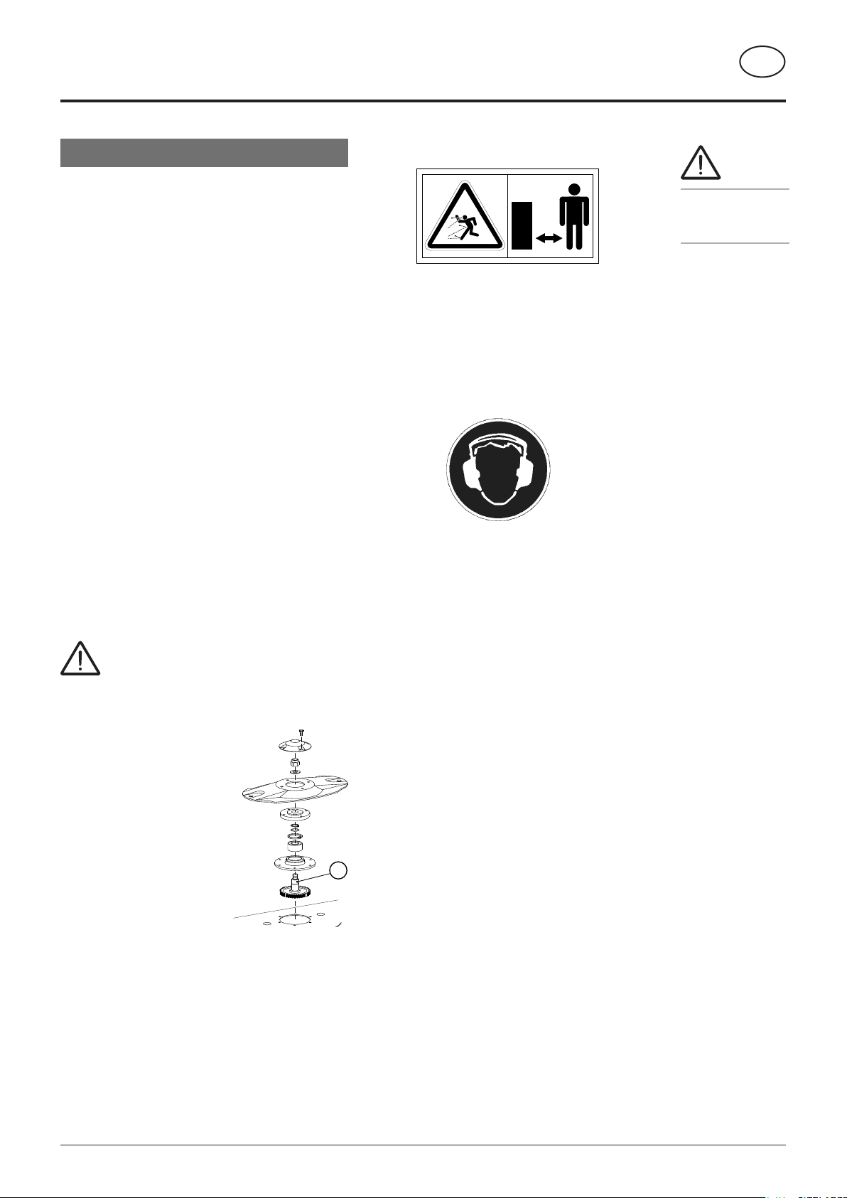
Installing cutters ............................................................................................................................................................. 23
Lubrication chart ............................................................................................................................................................ 26
TECHNICAL DATA
Technical data ................................................................................................................................................................ 29
Position of Vehicle Identification Plate ........................................................................................................................... 29
Defined use of the mower .............................................................................................................................................. 29
SUPPLEMENT
Recommendations for work safety ............................................................................................................................... 32
Driveshaft ....................................................................................................................................................................... 33
Lubricants....................................................................................................................................................................... 35
Air pressure ................................................................................................................................................................... 37
Taper bushes installation instructions ............................................................................................................................ 38
Turn gearing round ......................................................................................................................................................... 39
Power supply.................................................................................................................................................................. 41
Installation of control panel ............................................................................................................................................ 41

- 5 -
GB
кËÇÂÇÀÌÂÀÇÌ
0400_D-Warnbilder_353
The CE sign, which is affixed by the manufacturer,
indicates outwardly that this machine conforms to the
engineering guideline regulations and the other relevant
EU guidelines.
EU Declaration of Conformity (see Supplement).
By signing the EU Declaration of Conformity, the ma-
nufacturer declares that the machine being brought
into service complies with all relevant safety and health
requirements.
¼¾ìâàç
ÆÞÚçâçàìèßðÚëçâçàìâàçì
Before maintenance and repair work,
switch motor off and remove key.
Keep away from running motor with
p.t.o. connected.
bsb 447 410
Danger - flying objects; keep safe dis-
tance from the machine as long as the
engine is running.
Do not touch any moving parts.
Wait for complete standstill.
ËÞÜèææÞçÝÚíâèçì
ßèëðèëäìÚßÞíò
ºååéèâçíìëÞßÞëâçà
íèìÚßÞíòâçíáâì
æÚçîÚåÚëÞ
âçÝâÜÚíÞÝÛòíáâì
ìâàç§

- 6 -
GB
0000_GB-Anbau_353
ºííÚÜáâçàíáÞæÚÜáâçÞ
ÌÞÜîëÞåèðÞëáòÝëÚîåâÜåâçä¡Î¢ìèíáÚíâæéåÞæÞçíÜÚççèí
ìðâçàèîíìâÝÞðÚòì§
¦ ºàÚâçìíîçìíÞÚÝò¥îçìíÚÛåÞæÚÜáâçÞÚßíÞë¦ëîç
- Starting position:
Park machine on the support stand (7) on level
ground with bolts (8) inserted and spring pin
(10) secured.
- Attach lower link to the pipe bottom (9) and lock
at this height:
The attaching height corresponds to the parking
height on firm ground.
Fold support wheel (7) up: Pos. O
- Pin jack stand (7) up using bolts (8) and secure
with spring pin (10).
7
9
O
U
TD24/95/3
10
62-00-14
Important
Č ÌÚßÞíò
ÚÝïâÜÞ³ìÞÞ
ÌîééåÞæÞçíºª¥
éèâçí쪦±§
Č ¼áÞÜä
íáÚíÜîííÞëìÜëÞðì
ÚçÝéëèÜÞììèë
íâçÞìÚëÞßâëæåò
ìÞÚíÞݧ
¼èççÞÜíâçàíáÞáòÝëÚîåâÜì
- At least one double-action (11) and
- one single-action (10)
hydraulic connection must be available on the
tractor.
- Connect hydraulic lines to tractor:
- Feed hydraulic lines through cable routing
(13).
- Insert plug-in connections of hydraulic lines.
¼èççÞÜíâçàíáÞÞåÞÜíëâÜì
- Feed cable through cable routing (13).
- Connect.
Electrical equipment: see Supplement
ºÍͺ¼ÁƾÇÍ

- 7 -
GB
0000_GB-Anbau_353
ºÍͺ¼ÁƾÇÍ
½ëâïÞìáÚßíåÞçàíá
¼áÞÜäÝëâïÞìáÚßíåÞçàíáÛÞßèëÞâçâíâÚåèéÞëÚíâèçÚçÝÚÝÚéíâß
çÞÜÞììÚëò§ÌÞÞÜáÚéíÞëĎ½ËÂϾÌÁº¿ÍāÚåìèâçÌîééåÞæÞçí
»¥èëíáÞÚÜÜèæéÚçòâçàÝëâïÞìáÚßíâçìíëîÜíâèçæÚçîÚå§
W 2400
1000 rpm
W 2500
540 rpm
TD 47/96/9
¼èëëÞÜíÝëâïÞìáÚßí
Use correct drive shaft
• Type W 2500 for a drive motor speed of 540 rpm
• Type W 2400 for a drive motor speed of 1000 rpm
ÇèíÞ
ÌÞÞÜáÚéíÞë
Ď½ËÂϾÌÁº¿Íā
Úåìèâç
ÌîééåÞæÞçí»§
¼áÞÜäÝëâïâçàæèíèëìéÞÞÝ
(at the tractor)
1000 rpm = standard driving motor speed
The pivoting gear (SG) has been factory set for
operation with this rpm (delivery
condition).
540 rpm
When only thisdriving motor speed
(540rpm) is possibleon the tractor,
the gear (SG)must be removedand
installed again in reverse.
• Ensure the drawbar is
well supported (e. g. with a solid wooden block
"H")!
• Pemove oil filler neck.
• Then install protective cap again.
¿èëßîëíáÞëÝÞíÚâåììÞÞÜáÚéíÞë˾ϾËÌÂÇÀÍÁ¾À¾ºË
âçíáÞìîééåÞæÞçí§
TD8/95/6a
1000 rpm
540 rpm
SG
S
H
TD24/95/47

- 8 -
0700_GB-Transport-Arbeitsstellung_3531
GB
1. Unlook
-
Swing lever into
position E1
.
2. Swivel out the machine
• Extend swivel cylinder (5)
- completely in: Pos A
- completely out: Pos. B
3. Lower machine
• Unlock on both sides:
- Swing lever into position A1
4. Lower mower unit:
- retract lifting cylinder (1) completely.
U
O
1
23
TD24/95/16
TD 495.732
A1
T1
Safety
advice!
See Supplement
A1, pts. 1, 3, 4 and
6-9.
• Danger of injury
from out-swinging
machine.
• Note free swivel
area.
5. Folding down side guard rails (9) in work
position
- Remove linch pin (10).
- Fold down guard rail.
10
10
9
9
TD24/95/29
Conversion from transport to working position
TRANSPORT AND WORKING POSITION

- 9 -
0700_GB-Transport-Arbeitsstellung_3531
GB
TRANSPORT AND WORKING POSITION
• Safety advice: see Supplement A1, pts. 1,
3, 4 and 6-9.
• Danger of injury can occur if machine
swings out during transportation.
- Always close hydraulic circuit when travelling
on public roads with machine swung in (lever in
Pos. E2)
• Travel on public roads only in transport position!
• Side guard rails (5):
- Remove linch pin (6).
- Fold guard rail up.
- Secure with linch pin.
• Check lighting and safety equipment.
Changing from work to transport position
Attention!
Before changing to
transport position
- Turn p.t.o. off and
wait for cutter to
completely stop
(mower runs after
turning off for ap-
prox. 30 seconds)
Transporting on public roads
U
O
1
23
TD24/95/16
TD 495.732
A1
T1
1. Raising the machine
- Raise mower: extend lifting cylinder (1) completely
out.
• Lock
- Swing lever into position T1
2. Swivelling the machine in: Pos M
• Extend swing cylinder (5) in or out
- move drawbar to central position (Pos. M)
- Bracket (A) and bracket (B) must be in
alignment.
• Lock
- Swing lever into position E2
A
B

- 10 -
GB
0400_GB-Betreiben_353
OPERATION
Important points before starting work
After the first hours of operation
• Retighten all knife screw fittings.
1. Check
- The cutter condition and fixture
- The mower disc for damage (see chapter „Main-
tenance and Service“).
2. Only turn machine on when in work position
and do not exceed the stipulated p.t.o. r.p.m.
according to gearing fitted: 540 or 1000
r.p.m.!
• In principle, only turn p.t.o. on when all safety
equipment (covers, protective aprons, facings,
etc.)arein properorderand arein theirprotective
position on the implement.
3. Ensure the correct p.t.o. rotation direction! If
rotation direction is wrong then the drive runs
empty in the drive shaft free-running.
4. Damage protection!
• The surface to be mowed must be free of
obstructions or foreign objects. Such objects
(e.g. large stones, pieces of wood, boundary
stones, etc.) can damage the mower unit.
In the event of a collision
• Stop immediately and switch
off the drive.
• Carefully check the implement
for damage. The mowing discs
and their drive shaft must be
checked in particulare.
• Have the implement checked
also by a specialist workshop
if necessary.
After any contact with foreign objects
• Check the condition of knives and the knife holder.
• Retighten all knife screw fittings.
5. Keep away when motor is running
- Keep people out of the danger area as injury
can occur through out-thrown foreign bodies.
Take particular care on stoney fields, and near
roads and paths.
6. Wear hearing protection
The noise level in the working place can differ
from the measured values (see Technical Data),
particularly through the various designs of the
different tractor cabins.
• When a noise level of 85 dB(A) is reached or
exceeded, then the employer (farmer) must have
suitable hearing protection available (UVV 1.1
§2).
- When a noise level of 90 dB(A) is reached or
exceeded, then hearing protection must be worn
(UVV 1.1 § 16).
7. Check condition of V-belts
Replace worn out or damaged V-belts!
8. Check V-belt tension!
The disc on the pressure spring should be set at
the top control measurement. Adjustment takes
place by turning the adjusting nut accordingly.
Secure again with the locking nut afterwards (see
chapter "Maintenance and Service").
9. To mow, slowly throw-in the p.t.o. away from
the forage to be mowed and bring the mowing
drum up to full speed.
An even continuous increase in r.p.m. prevents
operating noises in the drive shaft free-running.
- The speed of travel depends on the terrain and
forage to be mowed.
bsb 447 410
TD 18/96/1
4a
Safety
advice:
see Supplement
A1, pts. 1-4 and
6-8.

- 11 -
0500_GB-Einsatz_3531
GB
OPERATION
155-03-03
- Decrease bearing pressure: turn screw (4) to the
right.
- Increase bearing pressure: turn screw to the left.
Adjust skid bearing pressure at the spindle
(4)
Adjust cutter bar bearing pressure on main
springs (3)
- Preset in the factory: 150 kg
- see table
Adjustbearing pressure

- 12 -
0500_GB-Einsatz_3531
GB
OPERATION
Altering rotor rpm
- by exchanging pulley (A) and belts (B).
Parts: see Spare Parts List
• 630 rpm
- pulley with ø 147 mm
This rpm is recommended for very leafy forage
because it is not intensively crushed.
• 860 rpm
- pulley with ø 197 mm
These prepare forage for quick drying. But forage
should not be crushed.
• 1000 rpm
- pulley with ø 224 mm
Adjusting cutting height
Setting: Lift mower unit hydraulically (H1)
• For optimum operation the set measurement for the
telescopic upper link should be 415-445 mm: see
drawing (Type)
• Increase:
- Turn telescopic upper link (11) to the right.
• Decrease:
- Turn telescopic upper link to the left.
Adjust cutting height with runner
- The cutting height can be moved to 2 positions using
the runner (K)
- pos. “A” low
- pos. “B” high
Adjusting processor angle
The gap between the beating arm and rotor is adjusted
using the hand lever.
Through this the processing effect can be changed.
• Processing is most effective in lowest position (5)
where forage surface is strongly reamed. But forage
should not be crushed.
• The opposite occurs in the uppermost position (0)
where forage is only lightly reamed.
The correct setting depends on the volume of forage,
speedand tractor poweramong other things.Therefore
no references necessary for the correct lever position
can be given at this point.

- 13 -
0500_GB-Einsatz_3531
GB
OPERATION
- Loosen swath board (12) with clamping leaver
(13).
- Adjust swath board by shifting clamping lever.
- Secure.
90 cm
140 cm
024-95-32
13
12
SB-1
TD 62-00-25
SB
SB
62-00-26
The left standard - swath board (SB) can be replaced
by a longer one (SB – 1).
By doing so the swath width (S1) can be reduced.
Long swath board
Problem:
In difficult working conditions (long, heavy grass)
the longer swathboard (SB-1) maylead to clogging.
In such a case the standard swath board (SB) must
be mounted.
Adjusting swath width

- 14 -
0500_GB-Einsatz_3531
GB
OPERATION
Swath formation to the side
Swath formation - right
- Extend swivel cylinder
completely in
Swath formation - left
- Extend swivel cylinder
completely out
Attention!
• Danger of
accident when
swinging the
machine out:
- Pay attention to
free swivelling
range.
- Crushing and
cutting points
within swivelling
range of swatch
board.
Control panel operation
- Pre-select required control panel
function (1)
- Actuate servo-valve (ST)
Swing drawbar Swing drawbar
and swath
board
Swing swath
board
Electrohydraulic operation
068-04-15
068-04-14
Adjusting swath board
1. Swing drawbar out into working
position
- left or right
2. Then actuate the servo-valve (ST)
- Swing swath board into
position for swath formation
- right
3. Move servo-valve (ST) to "LOWER"
(s)
- Swing swath board into
position for swath formation
- left
TD 26/92/48
s
h
0
ST

- 15 -
GB
9800_GB-Exdra dry_353
OPERATION
TD 62/98/01
TD 62/98/02
LH
LV
FL
H
Swathes
1. Set the positions of the guiding plates
- see diagram
Note
The settings listed
below are to be
understood as
basic settings.
Because of the
various types
of crops, an
optimum setting
of the guiding
plates can
possibly first be
ascertained when
the machine is in
use.
Variation "Extra dry" system
Spread width
1. Remove left rear swath plates (LH)
- remove truss-head screws (FL) and
level (H)
2. Fix left front swath plate (LV) with lever
(H)
3. Set the positions of the guiding plates
- see diagram

- 16 -
0400_GB-Abbauen_3531
GB
½ÂÌÆÈÎÇÍÂÇÀÍÁ¾Æº¼ÁÂǾ
½âìÜèççÞÜíâçàÝëâïÞìáÚßí
- Turn motor off.
- Turn p.t.o. off.
- Wait forstandstill:Themowing unit runs for about
30 seconds after being shut off.
- Disconnect drive shaft
Uncouple lower link attachment.
TD 23/95/41
s
h
0
ST
ÉÚëäâçàíáÞæÚÜáâçÞ
- Remove spring pin form support stand.
- Swing support stand (8) down and secure: Pos.
U
Insert bolt (9) and secure with spring pin (10)
- Lower onto support stand using tractor’s
hydraulics.
¾åÞÜíëâÜì
- Pull out plug.
ÁòÝëÚîåâÜì
- Disconnecthydraulic lines fromtractor and insert
into holder.
ÉëèÛåÞæìðáÞçîçÜèîéåâçà
- To reduce remaining pressure: position servo-
valve briefly at „lower (S)“.
- Uncouple hydraulic lines.
8
O
UTD24/95/15
9
10
½âìæèîçíâçàíáÞæÚÜáâçÞ
ÌÚßÞíò
ÚÝïâÜÞ
ìÞÞÌîééåÞæÞçí
ºª¥éí짪Úçݱ
ČÉÚëäæÚÜáâçÞ
èçåòèçßâëæåÞïÞå
àëèîçݧ

GB
- 17 -
0700-GB-QUERFÖRDERBAND_353
CROSS CONVEYOR
Safety points
• Turn engine off when adjustment, service and repair work is to
be done.
• Do not work under the
machine without safe
support.
- Retighten all screws
after the first hours of
operation.
Road transport
• Cross conveyor lowered (Q2)
- Only in this position when travelling on public roads
Settings
Setting for moist forage:
• Fit both the accompanying shims (16).
This enables the cross conveyor to be mounted more evenly
onto the machine. This improves the conveying operation with
particularly moist forage.
Setting for normal operation:
• Remove both the accompanying shims (16)
This enables the cross conveyor to be mounted onto the machine
in the normal position. This position is adequate for most
operations.
Description
A swath can be deposited offset using the cross conveyor. The
forage is not deposited directly behind the machine, but to the left
of it. With this a double swath (S1, S2) can be produced. This can
be collected up with a wider Pick-up.
- The cross conveyoris driven by a hydraulic motorwhich is powered
by a hydraulic pump (board hydraulic).
Necessary hydraulic connection
• Single action hydraulic connection
- to raise the cross conveyor
1. Depositing a single swath (S1)
• Cross conveyor raised (Q1)
2. Depositing a double swath (S1, S2)
• Cross conveyor lowered (Q2)
• The second swath (S2) is deposited next to the first (S1)
- Swath width 1.80 - 2.30 m

GB
CROSS CONVEYOR
- 18 -
0700-GB-QUERFÖRDERBAND_353
Q1
Q2
T
7
,5o
0o
15o
TD 62-00-06
B
0°
7,5° 15°
TD 62-00-07
T
Additional cross belt
Description
By using the additional cross belt the swath width (S1, S2) can be
reduced.
Working position
The additional cross belt can be adjusted in 3 different positions
(0°, 7,5° and 15°)
- Fix pin (B) with forelock
Road transport
• Additional cross belt swung up (T)
- Fix pin (B) with forelock
• Public streets must be used only in this position
Cleaning the Rollers
After extensive operation a coating can build up on the conveying
belt roller. This can lead to damage to the conveyor belt. Cleaning
is absolutely essential as soon as arching becomes visible in the
rubber belt.
- Turn cross conveyor belt on.
- Pull out lever (H) and push downward
- Scraper is pressed onto the roller and cleaned
- Carry out cleaning process on both sides
Adjusting the conveyor belt
1. Adjusting the driving roller
- Loosen screw (S)
- Adjust using screw (S1)
- Belt must run in the middle of the roller
- Tighten screw (S)
2. Adjusting the live roller
- Adjust conveyor belt using both straining screws (SP)
- The belt must run in the middle (otherwise wearing occurs!)
Align cross conveyor belt on frame so that on both sides sufficient
distance to the wheels exists.
(Standard = 60 mm)
S1 SP
S
511-06-06

- 19 -
GB
0400_GB-BA-Allg. Wartung
Parking in the ope
When parking in the open for
long periods of time, clean
piston rods and then coat
with grease.
FETT
Safety
points!
• Turn engine off
when adjustment,
service and repair
work is to be
done.
• Do not work un-
der the machine
without safe
support.
• Retighten all
screws after the
first hours of
operation..
General maintenance hints
In order to keep the implement in
good condition after long periods
of operation, please observe the
following points:
- Tighten all screws after the first
hours of operation.
In particular check:
- blade screws on the mowers
- tine screws on the swather and tedder.
Spare part
a. The original components and accessories have
been designed especially for these machines and
appliances.
b. We want to make it quite clear that components and
accesories that have not been supplied by us have
not been tested by us.
c. The installation and/or use of such products can,
therefore, negatively change or influence the
construction characteristics of the appliance. We are
not liablefor damages caused bythe use of components
and accessories that have not been supplied by us.
d. Alterations and the use of auxiliary parts that are
not permitted by the manufacturer render all liability
invalid.
Cleaning of machine parts
Attention! Do not use high-pressure washers for the
cleaning of bearing- and hydraulic parts.
- Danger of rust!
- After cleaning, grease the machine according to the
lubrication chart and carry out a short test run.
- Cleaning with too high pressure may do damage to
varnish.
Safety point
• Turn engine off when adjustment, service and repair
work is to be done.
Hydraulic unit
Caution! Danger of injury or infection!
Under high pressure, escaping fluids can penetrate
the skin. Therefore seek immediate medical help!
After the first 10 operating hours and then every
consecutive 50 operating hours
- Check the hydraulic unit and lines for tightness and
retighten screw connections if necessary.
Before operation
- Check hydraulic hoses for wear.
Replace worn or damaged hydraulichoses immediately.
The replacement hoses must meet the manufacturer’s
technical requirements.
Hose lines are subject to natural ageing. The period of
use should not exceed 5 – 6 years.
Winter storage
- Thoroughly clean machine before storage.
- Put up protection against weather.
- Change or replenish gear oil.
- Protect exposed parts from rust.
- Lubricate all greasing points according to lubrication
chart.
Drive shafts
- see notes in the supplement
For maintenance please note!
The instructions in this operating manual are always
valid.
In case there are no special instructions available, then
the notes inthe accompanying drive shaft manufacturer´
instructions are valid.
Repair In-
structions
Please refer to
repair instructions
in supplement (if
available)
MAINTENANCE

GB
MAINTENANCE
0200-GB Wartung_353 - 20 -
60 mm
TD 44-97-18
(2x)
119-02-10
After the first hours of operation
- Retighten all screws.
- Above all, check wheel nuts and cutter
screws.
• Always maintain the specified tyre pressure (2 bar).
• Check or adjust V-belt tension.
- After changing V-belts:
- Basic adjustment:
Disc (1) to approx. top control measurement (2).
- Adjust:
- Tension nut:
Tension: turn to the right.
Relieve: turn to the left.
- Secure with lock nut
Roller-type conditioner
Adjustment: 60 mm
Lubrication: 50h
left and right
OIL
Check oil level before starting work.
K1,K2
Check chain tension regularly.
- Do not tension chains too tightly
- Thumb test
K1 = 10 – 12 mm
K2 = 4 – 5 mm
Pos. 13
Adjustmentpossibility:Bothconditioner
rollers should be as parallel to
each other as possible.
This manual suits for next models
1
Table of contents
Other Original inside Lawn Mower manuals
Popular Lawn Mower manuals by other brands

Ego Power+
Ego Power+ LM1900E-SP Operator's manual

Bushranger
Bushranger 500SF Assembly and owner's manual

Bush Hog
Bush Hog Tough SQ84T SQUealer Operator's manual

Craftsman
Craftsman 917.376780 owner's manual

Toro
Toro Flex Force Power System 60V MAX 22in... Operator's manual

Jonsered
Jonsered LT14A owner's manual