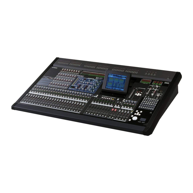
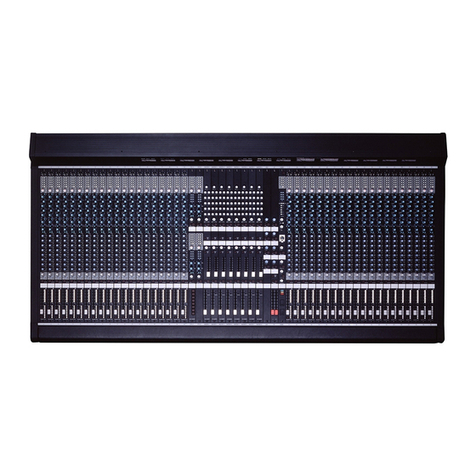
OTARI Status 18R User manual

STATUS 18R
Audio Mixing Console
Operation and Maintenance Manual
Third Edition
Ed. 3.1
May, 2000
Revised. September, 2000
Part No. OS3-609

Copyright © 1999, 2000 by Otari, Inc.
Printed in Japan
This manual may not be reproduced by any means without written permission.

SAFETY INSTRUCTIONS
1. Read Instructions: All safety and operating instructions should be
read before operation.
2. Retain Instructions: The safety and operating instructions should be
retained for future reference.
3. Heed Warnings: All warnings on the device and in the operating
instructions should be complied with.
4. Follow Instructions: All operating and use instructions should be
followed.
5. Water and Moisture: The device should not be used near water — for
example, near a bathtub, wash bowl, sink, laundry tub, in a wet
basement, near a swimming pool, etc.
6. Carts and Stands: The device should be used only with a cart or
stand that is recommended by the manufacturer.
7. Ventilation: The device should be situated so that its location or position
does not interfere with its proper ventilation. For example, the device
should not be situated on a bed, sofa, rug, or similar surface that may
block the ventilation openings; or, placed in a built-in installation, such as
a bookcase or cabinet that may impede the flow of air through the
ventilation openings.
8. Heat: The device should be situated away from heat sources such as a
radiator, heat register, stove or other appliances (including amplifiers)
that produce heat.
9. Power Sources: The device should be connected to a power supply
only of the type described in the operating instructions or as marked on
the device.
10. Grounding or Polarization: Precautions should be taken so that the
grounding or polarization means of the device is not defeated.
11. Power Cord Protection: Power supply cords should be routed so
that they are not likely to be walked on or pinched by items placed
upon or against them, paying particular attention to cords at plugs,
convenience receptacles, and the point where they exit from the
device.
12. Cleaning: The device should be cleaned only as recommended by the
manufacturer.
13. Non-Use Periods: The power cord of the device should be unplugged
from the outlet when left unused for a long period of time.
14. Object and Liquid Entry: Care should be taken that objects do not
enter and that liquids are not spilled into the enclosure through
openings.
15. Damage Requiring Service: The device should be serviced by
qualified service personnel when:
A. The power supply cord or the plug has been damaged; or
B. Objects have entered, or liquid has been spilled into the appliance;
or
C. The appliance has been exposed to rain; or
D. The appliance does not appear to operate normally or exhibits a
marked change in performance; or
E. The appliance has been dropped, or the enclosure damaged.
16. Servicing: The user should not attempt to service the device beyond
what is described in the operating instructions. All other service should
be referred to qualified personnel.
COMMUNICATION WITH OTARI
FOR SERVICE INFORMATION AND PARTS
All Otari products are manufactured under strict quality control. Each unit is
carefully inspected and tested prior to shipment.
If, however, some adjustment or technical support becomes necessary,
replacement parts are required, or technical questions arise, please contact
your Otari dealer or contact Otari at:
Otari, Inc. Otari Corporation
4-33-3 Kokuryo-cho, Chofu-shi, 8236 Remmet Avenue,
182-0022, Tokyo, Canoga Park, California 91304
Japan U.S.A.
Telephone: (81) 42481-8626 Telephone: (818) 598-1200
Fax: (81) 42481-8633 Fax: (818) 594-7208
Web Site: http://www.otari.co.jp Web Site: http://www.otari.com
Otari Europe GmbH. Otari Singapore Pte., Ltd
Rudolf-Diesel-Str.12 40 MacTaggart Road
D-40670 Meerbusch (Osterath) Singapore 1336-368085
Germany Telephone: (65) 284-7211
Telephone: (02159) 50861 Fax: (65) 284-4727
Another part of Otari’s continuing technical support program for our products
is the continuous revision of manuals as the equipment is improved or
modified. In order for you to receive the information and support which is
applicable to your equipment, and for the technical support program to
function properly, please include the following information, most of which can
be obtained from the Serial number label on the machine, in all
correspondence with Otari:
• Model Number:
• Serial Number:
• Date of Purchase:
• Name and address of the dealer where the machine was purchased and
the power requirements (voltage and frequency) of the machine.
CAUTION
To prevent fire or shock hazard:
Do not expose this unit to rain or moisture.
Do not remove panels (unless instructed to do so).
There are no user-serviceable parts inside.
Refer servicing to qualified service personnel.
PLEASE READ THROUGH THE SAFETY INSTRUCTIONS BELOW.

DEAR CUSTOMER:
TO ALLOW US TO SERVE YOU WITH THE
BEST CUSTOMER SUPPORT POSSIBLE,
PLEASE TAKE THE TIME TO FILL OUT
AND RETURN THE USER INFORMATION
FORM OPPOSITE THIS PAGE.
THANK YOU !

Please Read This First...
Congratulations on the purchase of your new STATUS Console!
In order for Otari to maintain contact with you regarding new system features for
your STATUS Console and to provide you with the best service possible, we ask
that you take a moment to fill out the form below and return it to us as soon as
possible. Our address is:
Otari, Inc.
7039 Tazawa,
Toyoshina-cho,
Minami-Azumi-gun,
Nagano
399-8203, JAPAN
Attn: Console Products Department
STATUS 18R Console Information
Company: ________________________________________________
Contact: ________________________________________________
Address: ________________________________________________
City: ________________________________________________
State & ZIP: ________________________________________________
Phone: ________________________________________________
Fax: ________________________________________________
Dealer: ________________________________________________
Purchase Date: ________________________________________________
Console S/N: ________________________________________________
Type of Business (Please check all that apply)
___Music Recording
___TV Production
___Film Production
___Broadcasting
___Other (describe) ________________________________________________
________________________________________________
________________________________________________
________________________________________________
________________________________________________


Safety Instructions.....................................iii
Section 1 Introduction
1.1 System Description ...............................1-1
1.1.1 Analog Features............................1-1
1.1.2 Digital Control Features ......................1-1
1.1.3 Dual Path Design ...........................1-1
1.1.4 Minimum Noise Gain Summing ................1-2
1.1.5 Low Noise VCA Implementation................1-2
1.2 Using this Manual ................................1-2
1.2.1 Section Descriptions ........................1-2
1.2.2 Terminology ...............................1-3
1.3 STATUS Specifications ............................1-4
Section 2 Installation
2.1 Introduction .............................................2-1
2.2 Preparation ..............................................2-1
2.2.1 Physical Precautions ..............................2-1
2.2.2 Ventilation Considerations .........................2-1
2.2.3 Electrical Power Considerations....................2-1
2.2.4 Cable ............................................2-2
2.2.5 Cable Routing ....................................2-2
2.2.6 Grounding and Shielding ..........................2-2
2.3 Uncrating................................................2-3
2.4 Inspection ...............................................2-4
2.5 Shipping Bracket Removal and Leg Installation ............2-4
2.6 Interfacing Audio.........................................2-4
2.6.1 Cable Access.....................................2-4
2.6.2 Interface Connectors ..............................2-5
2.6.3 Interfacing Microphone Cables.....................2-5
2.6.4 Interfacing Audio to Consoles
with Patchbays ...................................2-6
2.6.5 Interfacing Audio to Consoles
without Patchbays ...............................2-10
2.6.6 Interfacing Time Code............................2-13
2.7 Connecting Power Supply Cables .......................2-14
2.8 Connecting Eagle Automation ...........................2-14
2.8.1 Automation PC Specifications ....................2-14
2.8.2 Console Connection .............................2-14
2.9 Interfacing the Optional PicMix Surround
Monitor System.........................................2-15
2.10 Set-up And Initial Turn-on..............................2-15
2.10.1 Normalizing the Console ........................2-15
2.10.2 Powering the Console ..........................2-16
2.10.3 Monitor System Setup ..........................2-16
Section 3 Controls and Indicators
3.1 Overview3.1 Overview..................................3-1
3.1.1 Console Layout...................................3-2
3.1.2 Digital Master Module .............................3-3
3.1.3 Input Module .....................................3-4
3.1.4 Input Module LED Meter and Status Display........3-5
3.1.5 LCD Menu System................................3-5
3.2 Master Section ..........................................3-6
3.2.1 Overview .........................................3-6
3.2.2 Track Assign Source ..............................3-6
3.2.3 Track Assignment.................................3-7
3.2.4 Aux Sends .......................................3-8
3.2.5 Solo Safe .......................................3-10
3.2.6 Write, Update ...................................3-10
3.2.7 Channel Path and Mix Path ......................3-10
3.2.8 Edit Buttons.....................................3-12
3.2.9 Selection Buttons................................3-14
3.2.10 Soft Key .......................................3-16
3.2.11 Presets ........................................3-17
3.3 Digital Master Module...................................3-18
3.3.1 LCD Display.....................................3-18
3.3.2 Function Keys F1–F3 ............................3-18
3.3.3 Solo Clear.......................................3-19
3.3.4 Solo Mode ......................................3-19
3.3.5 Talkback ........................................3-21
3.3.6 Control Room ...................................3-21
3.3.7 Meter Display....................................3-22
3.4 Input Module ...........................................3-23
3.4.1 Input............................................3-23
3.4.2 Aux .............................................3-23
3.4.3 EQ..............................................3-24
3.4.4 Fader Section ...................................3-25
3.4.5 Select Button....................................3-26
3.5 Analog Master Section..................................3-27
3.5.1 Oscillator........................................3-27
3.5.2 Aux Masters.....................................3-27
3.5.3 Talkback/Comm.................................3-27
3.5.4 Studio/Effects ...................................3-28
3.5.5 Control Room ...................................3-29
3.5.6 Stereo Mix ......................................3-30
3.6 Master Meter...........................................3-31
3.7 Patchbay...............................................3-32
3.7.1 Introduction .....................................3-32
3.7.2 Master Section Patch Points .....................3-32
3.7.3 Input Module Patch Points .......................3-35
3.7.4 Tie Lines ........................................3-36
3.8 Stereo Input Module ....................................3-37
3.8.1 Introduction .....................................3-37
3.8.2 Input Section ....................................3-37
3.8.3 Aux Section .....................................3-37
3.8.4 Return Path EQ..................................3-38
3.8.5 M/S Section.....................................3-39
3.8.6 Main Path EQ ...................................3-39
3.8.7 Select Button....................................3-40
3.8.8 Fader Section ...................................3-40
3.8.9 Stereo Patch Points .............................3-42
Section 4 Operation
4.1 Introduction .............................................4-1
4.2 Console Components....................................4-1
4.2.1 Input Module .....................................4-1
4.2.2 Digital Master Module .............................4-2
4.2.3 Patch Bay ........................................4-2
4.3 Getting Started ..........................................4-3
4.3.1 Booting the Console ..............................4-3
4.3.2 Initial Setup.......................................4-3
4.4 Module Editing Basics ...................................4-4
4.4.1 Introduction ......................................4-4
4.4.2 Module States ....................................4-4
4.4.3 Switch States.....................................4-4
4.4.4 Selecting a Module ...............................4-5
4.4.5 Edit Buttons ......................................4-5
4.4.6 Selection Buttons .................................4-6
4.5 Editing Input Module Switches............................4-8
4.5.1 Setting Switches on One Module ..................4-8
4.5.2 Setting Switches on a
Number of Modules...............................4-8
Table of Contents
August 1999 vii

4.6 Undoing Changes ......................................4-10
4.6.1 Module Undo....................................4-10
4.6.2 Swap Last State.................................4-10
4.7 Copying Master Section Switch Settings to
Input Modules ..........................................4-12
4.7.1 Copying Switch Settings to One Module ..........4-12
4.7.2 Copying Switch Settings to a
Number of Modules..............................4-12
4.7.3 Copying Switch Settings to Modules on Cue ......4-12
4.7.4 Copying One or a Few Switches to a Module .....4-13
4.7.5 Copying One or a Few Switches from
One Module to Another ..........................4-14
4.8 Select Groups..........................................4-14
4.8.1 Select Group Buttons............................4-14
4.8.2 Defining a Select Group..........................4-14
4.8.3 Using Select Groups.............................4-15
4.8.4 Loading and Saving Select Group Banks .........4-15
4.9 Presets ................................................4-16
4.9.1 Preset Buttons ..................................4-16
4.9.2 Storing the Master Section in a Preset ............4-16
4.9.3 Storing One or a Few Switches in a Preset........4-16
4.9.4 Using Presets ...................................4-16
4.9.5 Loading and Saving Preset Banks . . . .............4-17
4.10 Soft Key ..............................................4-18
4.10.1 Soft Key Buttons ...............................4-18
4.10.2 Programming a Soft Key........................4-18
4.10.3 Using Soft Keys ................................4-18
4.11 Solo System ..........................................4-19
4.11.1 Introduction ....................................4-19
4.11.2 Solo Modes....................................4-19
4.11.3 Selection Modes ...............................4-20
4.11.4 Using the Solo System .........................4-20
4.12 Aux Send Operation...................................4-22
4.12.1 Pre and Post...................................4-22
4.12.2 Pre Fader Aux Muting ..........................4-23
4.12.3 Module Indication ..............................4-23
4.12.4 Aux Master Mutes..............................4-23
4.13 Fader Grouping .......................................4-24
4.13.1 Overview.......................................4-24
4.13.2 Normal Operation ..............................4-24
4.13.3 Group Setup Mode.............................4-24
4.13.4 Group Setup Mode Functions...................4-25
4.13.5 How the Group Master Works ..................4-27
4.13.6 Grouping Limitation for Solo Interlock Mode .....4-27
4.14 Snapshots ............................................4-28
4.14.1 Overview.......................................4-28
4.14.2 Snapshot Keys.................................4-28
4.14.3 Fader Ramp Time ..............................4-28
4.14.4 Storing Snapshots..............................4-28
4.14.5 Recalling Snapshots............................4-29
4.14.6 Naming Snapshots .............................4-29
4.15 Image Recall ..........................................4-30
4.15.1 Overview.......................................4-30
4.15.2 Display Modes Overview........................4-31
4.15.3 Nulling the Console.............................4-33
4.15.4 Nulling Display Mode Operation .................4-36
4.15.5 Exiting Image Recall Mode......................4-36
4.16 User Preference System (UPS) .........................4-37
4.16.1 Overview.......................................4-37
4.16.2 Saving UPS Settings ...........................4-37
4.16.3 Loading UPS Settings ..........................4-37
4.16.4 Reloading Factory Defaults .....................4-37
4.17 Time Code Generator .................................4-38
4.17.1 Controls .......................................4-38
4.17.2 Using the Time Code Generator.................4-38
Section 5 Eagle Automation
5.1 Precaution...............................................5-1
5.2 Installing and Running Eagle Automation ..................5-2
5.2.1 Software Installation...............................5-2
5.2.2 Eagle Startup and Configuration ...................5-3
5.2.3 Using Eagle Automation...........................5-5
5.3 Status Automation Controls ..............................5-6
5.3.1 Write and Update Buttons.........................5-6
5.3.2 Auto Button ......................................5-6
5.3.3 Level and Status Display ..........................5-6
5.4 Master Automation Controls..............................5-7
5.4.1 Automation Main Menu ...........................5-7
5.4.2 SWITCH Menu ...................................5-8
5.4.3 OPTS (Options) Menu.............................5-8
5.4.4 Automation Options Menu (Shift-Automation).......5-9
5.4.5 TCIN Menu .......................................5-9
5.4.6 TCGEN Menu ...................................5-10
5.4.7 TCGEN SET Menu...............................5-10
5.4.8 TCGEN Time Code Input.........................5-10
5.4.9 GLIDE Menu ....................................5-11
5.5 Eagle Windows.........................................5-12
5.5.1 Eagle Main Screen...............................5-12
5.5.2 Console Window ................................5-13
5.5.3 Console Controls Window .......................5-14
5.5.4 Time Line Window ...............................5-14
5.5.5 Events Window..................................5-15
5.5.6 Mix Controls Window ............................5-16
5.5.7 Time Code Window..............................5-16
5.5.8 Time Code Window Options .....................5-16
5.5.9 Status Window ..................................5-17
5.5.10 Record Controls Window .......................5-17
5.5.11 Tool Bar .......................................5-17
5.5.12 Info Bar ........................................5-17
5.5.13 Mix Edit Window ...............................5-18
5.5.14 Mix Processing Window ........................5-23
5.5.15 Automation Preferences - Display Options .......5-24
5.5.16 Automation Preferences - Mix Options...........5-25
5.5.17 Track Sheet Window ...........................5-26
5.5.18 Console Preferences - Info......................5-27
5.5.19 Console Preferences - Settings .................5-27
5.6 Eagle Quick Tour .......................................5-28
5.6.1 Automation Overview ............................5-28
5.6.2 Setting Incoming Time Code .....................5-29
5.6.3 Getting Started ..................................5-30
5.6.4 Starting a New Mix ..............................5-30
5.6.5 Isolating Switches ...............................5-31
5.6.6 Setting End of Mix Processing. . . . . ...............5-32
5.6.7 Setting All Faders to Write........................5-33
5.6.8 Writing a Mix Pass ...............................5-34
5.6.9 Playing Back the Mix.............................5-34
5.6.10 Writing Single Faders ...........................5-35
5.6.11 Using the Auto Button ..........................5-35
5.6.12 Punching In Data ...............................5-36
5.6.13 Archiving (Saving) the Mix.......................5-36
5.6.14 Recalling Mixes ................................5-37
5.6.15 Undo and Redo ................................5-37
5.7 Introduction to Switch Automation.......................5-38
5.7.1 Writing Switches.................................5-39
5.7.2 Editing Previously Written Switch Moves ..........5-40
5.7.3 Trimming Switches ..............................5-41
Table of Contents STATUS 18R Operation and Maintenance Manual
viii August 1999

5.8 How To…..............................................5-42
5.8.1 How to Select Faders ............................5-42
5.8.2 How to Select Switches..........................5-42
5.8.3 How to Start a Mix...............................5-43
5.8.4 How to Use Mix Edit Merge ......................5-44
5.8.5 How to Use Mix Edit Copy .......................5-45
5.8.6 How to Use Mix Edit Swap.......................5-46
5.8.7 How to Use Mix Edit Switches ...................5-48
5.8.8 How to Use Mix Edit Faders......................5-49
5.8.9 How to Store Snapshots As Events...............5-50
5.8.10 Using Events ...................................5-51
5.8.11 Editing Time Code Prompts.....................5-52
5.9 Manual Fader Automation Modes .......................5-53
5.9.1 Introduction .....................................5-53
5.9.2 Isolate Mode (Manual Faders) ....................5-53
5.9.3 Auto Glide (Manual Faders).......................5-54
5.9.5 Write (Manual Faders)............................5-55
5.9.6 Enter Write (Manual Faders) ......................5-55
5.9.7 Leave Write (Manual Faders) .....................5-56
5.9.8 Update (Manual Faders)..........................5-56
5.9.9 Leave Update (Manual Faders) ...................5-57
5.9.10 Offset Write (Manual Faders) ....................5-57
5.10 Moving Fader Automation Modes ......................5-58
5.10.1 Introduction ....................................5-58
5.10.2 Isolate Mode ...................................5-58
5.10.3 Auto Glide .....................................5-59
5.10.4 Read ..........................................5-59
5.10.5 Write ..........................................5-60
5.10.6 Leave Write ....................................5-60
5.10.7 Update ........................................5-61
5.10.8 Leave Update ..................................5-61
5.10.9 Touch Modes and Fader Flip....................5-62
5.10.10 Touch Write ..................................5-62
5.10.11 Touch Update ................................5-63
Section 6 Calibration and Maintenance
6.1 Removing Modules from the Console .....................6-1
6.2 Setting Tape Input Sensitivity .............................6-1
6.3 Calibrating the Input Modules.............................6-2
6.3.1 Introduction.......................................6-2
6.3.2 Required Equipment ..............................6-2
6.3.3 Calibrating Input Modules .........................6-2
6.4 Setting Bus Output Levels ................................6-4
6.4.1 Calibrating Track Bus Outputs .....................6-4
6.4.2 Calibrating Stereo Bus Outputs ....................6-4
6.4.3 Calibrating Stereo Mechanical Meters ..............6-5
6.5 Assigning Talkback to Aux Sends.........................6-6
6.6 Internal Termination of VITC Input .........................6-7
6.7 Changing AC Voltage ....................................6-8
6.8 Setting Module Types ....................................6-8
6.9 Saving and Clearing Console NOVRAM ...................6-9
Appendix A LCD Menu Reference
Appendix B Dynamics Option
B.1 Introduction ....................................B-1
B.2 A Dynamics Primer...............................B-1
B.3 Installation .....................................B-4
B.4 Dynamics Controller ..............................B-6
B.5 Operation .....................................B-11
B.5.1 Gate Parameters ..........................B-11
B.5.2 Compressor/Limiter Parameters ..............B-12
B.5.3 Linking .................................B-12
B.5.4 External Keying of Noise Gates ...............B-13
B.5.5 External Keying of Compressor/Limiters ........B-13
B.5.6 Dynamics Presets .........................B-14
B.5.7 Saving and Loading Dynamics Preset and
Image Files to Floppy ......................B-15
B.5.8 Viewing Gain Reduction on the Console Meters ..B-16
STATUS 18R Operation and Maintenance Manual Table of Contents
August 1999 ix


1.1 System Description ...............................1-1
1.1.1 Analog Features............................1-1
1.1.2 Digital Control Features ......................1-1
1.1.3 Dual Path Design ...........................1-1
1.1.4 Minimum Noise Gain Summing ................1-2
1.1.5 Low Noise VCA Implementation ................1-2
1.2 Using this Manual ................................1-2
1.2.1 Section Descriptions ........................1-2
1.2.2 Terminology ...............................1-3
1.3 STATUS Specifications ............................1-4
August 1999
Section 1 Introduction


1.1 System Description
The STATUS 18R is a digitally controlled analog audio console. The heart of the console
is the Status Control System (SCS), a central control panel that manages most aspects
of the console’s operation. The SCS eliminates the need for redundant switches on the
input modules and provides a simple, logical way of operating the console.
Fader levels and most switching and signal routing functions are under computer
control. This provides for snapshot store and recall of console switch states and mix
levels. Optional DISKMIX automation provides dynamic automation of faders and mutes.
With the STATUS Image Recall feature, the position of all Input Module knobs and
switches can be stored, then manually reset, guided by each module’s LED display.
1.1.1 Analog Features
• 12 Track Buses split to 24 discrete Track Outputs, 8 Aux Buses and 1 Stereo Mix
Bus.
• Dual Path I/O modules with 4 Band EQ that may be assigned to either path or split
between the two.
• All Master Outputs are balanced +4 dBu. Module Insert Send and Direct Out are
unbalanced 0.5 dBu.
• AFL, PFL or In Place Solo independently selectable on each path.
• Extensive monitoring facilities with 8 Sources and Near Field Monitor Output.
• Complete Slate, Studio and Cue Communications included.
1.1.2 Digital Control Features
• Console Snapshot storage and recall of all computer controlled Input Module
switches.
• Storage of all Input Module pot and switch positions. Knobs and mechanical
switches are then manually matched to the stored settings with the aid of the
module LED display.
• User Programmable SoftKey for programming regularly used functions.
• Single or Multiple modules may be “Selected” and edited simultaneously.
• CompuCal™ Computer calibration of internal signal levels and meters.
• Programmable user presets for defining master switching functions.
• System software and files reside on the console’s on-board floppy disk drive.
1.1.3 Dual Path Design
The STATUS 18R employs an in-line I/O MODULE design which places all input and
output controls and electronics for two audio channels within a single module. This
creates a compact system that is functionally versatile, yet simple to operate. The
uncluttered layout provides a quick understanding of each control’s location and
purpose. Signal flow is straightforward and easy to follow.
1.1.4 Minimum Noise Gain Summing
All Multitrack and Aux buses employ Minimum Noise Gain Summing. When a module is
not assigned, it is completely disconnected from its summing bus. Since the noise gain
of a summing bus is dependent on the number of inputs summed, when only 3
channels, for example, are assigned to a Group Bus, the noise of that bus is the same
as if the console had only three input modules.
1.1.5 Low Noise VCA Implementation
The STATUS 18R console uses premium grade Voltage Controlled Amplifiers (VCAs).
Bias currents are set for lowest noise and optimum distortion specifications. When gain
is required, it is added within the VCA circuit itself, not in the following stages, to reduce
overall system noise.
September 2000 1 - 1
STATUS 18R Operation and Maintenance Manual Section 1 Introduction

1.2 Using this Manual
This manual contains all of the information that you need to connect, calibrate, operate
and maintain the STATUS 18R console.
When learning to operate the console, it is recommended that you review Section 3 to
familiarize yourself with control and indicator terminology before moving on to Section 4,
Operation and Section 5, Eagle Automation.
Appendix, contains an LCD Menu Reference that describes all of the LCD Menus. Refer
to this for a capsule description of what each LCD selection button does.
1.2.1 Section Descriptions
Section 2 - Installation: This section contains connector pinouts and instructions for
unpacking and identifying the equipment shipped with the console. Guidelines and
recommendations for installing and interfacing the console are also included.
Section 3 - Controls and Indicators: Section 3 identifies each control and indicator of
the STATUS 18R console. A brief description of each item and it’s function is included.
Section 4 - Operation: This section describes the operation of the console and gives
step-by-step examples of how various tasks are accomplished.
Section 5 - Eagle Automation: Section 5 covers all aspects of Eagle Automation from
Fader modes to offline utilities. The Quick Tour section takes you through a simple mix
session using Eagle Automation.
Section 6 - Alignment and Maintenance: This section contains information for
installing software and setting up the console. Instructions for using the CompuCal
system to align the internal levels and meters is also included.
Appendices: The Appendices contains additional reference material for operating the
STATUS 18R.
1.2.2 Terminology
I/O modules on the STATUS 18R incorporate a Channel Path (CHAN) and a Mix Path
(MIX). This can cause confusion when referring to the Channel Path on a given “Channel”
of the console. The terms “Track” and “Group” have a similar problem. When used
alone, the words “Track”, “Group” and “Channel” should read in context of the section
they are used in.
Where possible the following convention will be used when referring to Channels, Tracks
and Groups:
• Channel: Used by itself, Channel usually refers to a single audio path on a console or
tape machine.
• Path: A Path refers the route that a signal follows through the Input Module. This could
be the Channel or Mix Path.
• Channel or Chan Path: Refers to the signal path on an I/O module that is normally
used for assigning to the Track Outputs. This path is controlled by the upper fader and
is color coded Light Green.
• Mix Path: Refers to the signal path on an I/O module that is normally used for mixing
because it is closest to the engineer. This path is controlled by the lower fader and is
color coded Violet.
1 - 2 August 1999
Section 1 Introduction STATUS 18R Operation and Maintenance Manual

• Group: Refers to a number of items related to each other for some purpose. This
could be a Select Group, a Fader Group, a Group Bus or a Group (Track) Output.
• Select Group: Refers to a group of Input Modules attached to the Master Section of
the console at the same time. Group A, B and C buttons on the Master section store
preset Select Groups for recall.
• Fader Group: Refers to a group of faders whose levels are controlled by a Master
Fader.
• Group Bus: One of 24 Group Buses in the console. A Group Bus sums signals that
are assigned to it by the Module’s Track Assign Matrix.
• Group Output: Refers to output of the 24 Group Buses that normally feed a multitrack
recorder. The terms Group Output, Bus Output and Track Output are used
interchangeably.
• Track: The term Track used by itself normally refers to a record/playback channel on a
multitrack recorder.
• Track Assign: Refers to the matrix that normally routes a signal to a track on a
multitrack recorder. In reality, the signal is being routed to a Group Output which is
connected to the input of a track on a multitrack recorder.
• Track Bus: Means the same as Group Bus.
August 1999 1 - 3
STATUS 18R Operation and Maintenance Manual Section 1 Introduction

1.3 STATUS Specifications
Input Impedance Microphone > 2 k Ohms
Line Level Inputs > 12 k Ohms
All Outputs Impedance < 50 Ohms
Nominal Level (Balanced Outputs) +4 dBu
Nominal Level (Unbalanced Outputs) +0.5 dBu
Maximum Level Before Clipping (Balanced Outputs) +26 dBu
Maximum Level Before Clipping (Unbalanced Outputs) +21.5 dBu
Maximum Gain (Source to Track or Stereo Bus)
Microphone 74 dB
Line 48 dB
Tape 12 dB
Frequency Response (At Nominal Level, Filters and EQ Out)
Line to Track Bus Out 10 Hz - 20 kHz, +0/-.25 dB
Mic to Track Bus Out 20 Hz - 20 kHz, +0/-.25 dB
Tape to Stereo Bus Out 10 Hz - 20 kHz, +0/-.25 dB
Noise (20 Hz – 22 kHz, No Weighting, Input Termination 600Ω)
Mic (EIN 64dB Gain, 200 Ohms) -127 dBu
Track Buses (1 Path Assigned, Unity Gain) -86 dBu
Track Buses (16 Paths Assigned, Unity Gain) -72 dBu
Stereo Buses (1 Path Assigned, Unity Gain) -86 dBu
Stereo Buses (16 Paths Assigned, Unity Gain) -72 dBu
Distortion (THD+Noise, 20 Hz–20 kHz, at Nominal +4 dBu)
Line In to Track Out 0.05%
Tape In to Track Out 0.05%
Crosstalk Between Track Buses (No Panner) > 90 dB (1 kHz)
> 80 dB (20 Hz–20 kHz)
Between Stereo (L/R) Buses (Panner) > 70 dB (1 kHz)
> 65 dB (20 Hz–20 kHz)
Current Draw 24/24 Mainframe 245 VA Typical 415 VA Max.
32/32 Mainframe 326 VA Typical 645 VA Max.
40/40 Mainframe 408 VA Typical 645 VA Max.
48/48 Mainframe 490 VA Typical 645 VA Max.
Console Heat Dissipation 24/24 Mainframe 466 BTU/Hr. Typical 790 BTU/Hr. Max.
32/32 Mainframe 621 BTU/Hr. Typical 1230 BTU/Hr. Max.
40/40 Mainframe 777 BTU/Hr. Typical 1230 BTU/Hr. Max.
48/48 Mainframe 932 BTU/Hr. Typical 1230 BTU/Hr. Max.
Power Supply Heat Dissipation
24/24 Mainframe 508 BTU/Hr. Typical 860 BTU/Hr. Max.
32/32 Mainframe 677 BTU/Hr. Typical 1215 BTU/Hr. Max.
40/40 Mainframe 847 BTU/Hr. Typical 1215 BTU/Hr. Max.
48/48 Mainframe 1016 BTU/Hr. Typical 1215 BTU/Hr. Max.
Power Supply Fuses 110 VAC, 5 Volt Supply 3 Amp Slow Blow
110 VAC, Bipolar 16 Volt Supply 3 Amp Slow Blow
110 VAC, +48 Volt Supply 1/2 Amp Slow Blow
220 VAC, 5 Volt Supply 1.5 Amp Slow Blow
220 VAC, Bipolar 16 Volt Supply 1.5 Amp Slow Blow
220 VAC, +48 Volt Supply 1/4 Amp Slow Blow
1 - 4 August 1999
Section 1 Introduction STATUS 18R Operation and Maintenance Manual

Dimensions
August 1999 1 - 5
STATUS 18R Operation and Maintenance Manual Section 1 Introduction
24.9
(63.2)
INCHES
(CM)
28.7
(72.9)
35.0
(88.9)
38.8
(98.6)
30.3
(77.0)
24.9
(63.2)
4.8
(12.2)
33.9
(86.1)
FRAME LENGTHS
S18-24
S18-24-PB
S18-32
S18-32-PB
S18-40
S18-40-PB
S18-48
63.9
63.9
63.9
75.1
75.1
86.3
86.3
(162.3)
(162.3)
(162.3)
(190.7)
(190.7)
(219.2)
(219.2)


Section 2 Installation
August 1999
2.1 Introduction .............................................2-1
2.2 Preparation ..............................................2-1
2.2.1 Physical Precautions ..............................2-1
2.2.2 Ventilation Considerations .........................2-1
2.2.3 Electrical Power Considerations. . ..................2-1
2.2.4 Cable ............................................2-2
2.2.5 Cable Routing ....................................2-2
2.2.6 Grounding and Shielding ..........................2-2
2.3 Uncrating................................................2-3
2.4 Inspection ...............................................2-4
2.5 Shipping Bracket Removal and Leg Installation ............2-4
2.6 Interfacing Audio .........................................2-4
2.6.1 Cable Access.....................................2-4
2.6.2 Interface Connectors ..............................2-5
2.6.3 Interfacing Microphone Cables.....................2-5
2.6.4 Interfacing Audio to Consoles
with Patchbays ...................................2-6
2.6.5 Interfacing Audio to Consoles
without Patchbays ...............................2-10
2.6.6 Interfacing Time Code............................2-13
2.7 Connecting Power Supply Cables .......................2-14
2.8 Connecting Eagle Automation ...........................2-14
2.8.1 Automation PC Specifications . . ..................2-14
2.8.2 Console Connection .............................2-14
2.9 Interfacing the Optional PicMix Surround
Monitor System.........................................2-15
2.10 Set-up And Initial Turn-on..............................2-15
2.10.1 Normalizing the Console ........................2-15
2.10.2 Powering the Console ..........................2-16
2.10.3 Monitor System Setup ..........................2-16

Table of contents
