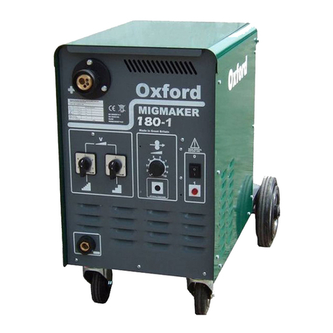
Oxford MULTIMIG CS273 User manual

Oxford
MULTIMIG CS range of Compact / Separate
wire feed MIG welding machines
Caution before installing or operating this machine ensure all
instructions and warnings have been read and understood.
INSTRUCTION MANUAL

Safety Guidelines
This machine is designed for use only by experienced operators only.
All users must be competent, trained & familiar with welding processes
and safe electrical practices.
Before using this product, you should carry out a risk assessment &
take appropriate action to minimize all risks.
Some of the risks involved are listed below.
•Risk of burns & eye damage.
•Risk of electrocution.
•Risk to health from welding fume inhalation.
•Risk of fire caused by welding sparks etc.
•Risk from installing & using welding gas & cylinders.
•Risk of pacemaker malfunction from strong magnetic fields.
•Risk of bodily crush damage from wire drive system gears & rollers.
•Risk from a build up of gas in confined spaces.
•Risks from welding wire, sharp wire can cause blindness or other
injury.
•Other risks may be present.
The British Health and Safety Executive publish documents regarding
this such as ISBN 0717607046 (Electrical safety in arc welding), and
many others.
For outdoor use this machine should be sheltered from rain etc, the
enclosure gives protection to IP23S.
Only use this machine in the upright position.
Only use correct type of ‘MIG’ gas, never use any gas not designed for
arc welding.
Do not obstruct the ventilation on the rear or front of this machine.
Do not try to connect this unit to any other supply other than what’s
marked on the rear.
Always keep this machine maintained in accordance with this manual &
good workshop practice.
DO NOT TAKE ANY UNNECESSARY RISKS

Pre installation & EMC information
The installer of this equipment must make an assessment of the area before
installing.
It is the user’s responsibility to ensure that if any electromagnetic disturbances
are detected to resolve this before continuing.
As with other welding machines it is preferable to use this machine as far
away as possible from sensitive electrical or electronic equipment such as
computers, telecom equipment, safety critical equipment, transmitters and
receiving equipment etc.
There is a risk to sensitive equipment from radiated or conducted emissions
from this machine.
This machine is designed for use in industrial premises, when used in other
environments there could be potential difficulties with electromagnetic
interference with other equipment.
Consideration must be also given to other premises as the emissions may not
be limited to the installed premises.
The following are methods to reduce emissions.
1) Keep all welding cables short close together and at ground level.
2) Equipotential bonding of metal components in the work area and
bonding of the work piece can be considered however there are
electrical safety implications for the operator with increased risk of
shock if the electrode is touched; therefore it is important the operator
is aware and adequately protected from making contact with the work
and the electrode. Before bonding the area and work piece consult
an experienced electrician.
3) This equipment must be properly maintained and all screws holding the
sides etc kept in place.
4) Sometimes it may be necessary to fit additional mains input filters or
even screen the cables and / or work area. This will involve consulting
an experienced engineer.
Declaration of conformity
Oxford MULTIMIG CS range 270-510AMIG welding machines
This equipment is manufactured to comply with 2006/95/EEC, BS EN 60974-1
This equipment is manufactured to comply with 89/336/EEC, BS EN 60974-10
This equipment is manufactured to RoHS directive 2006/95/EU
Date 01/02/2023
R P Rycroft R Rycroft Oxford Welders, TechnicalArc Ltd, York UK

Overview
Heavy duty Inverter MIG, with 4 roll wire drive, MMA ARC welding & DC TIG, real
industrial machines built to work hard for 25+ years. Simple to use but packed full of
features to provide superior welding performance with ultra low power consumption.
One power source covers both compact & SWF MIG. Simply plug in our 4X wire
feeder & you have SWF MIG!
Guaranteed better welding performance than any traditional transformer MIG! Low
spatter, instant arc starts, infinite control of output to 1A & 0.1V. Despite the
performance benefits these are even simpler to set & use than our old transformer
based machines & are a real joy to weld with. Weld anything from the thinnest car
panels up to structural steel buildings & large earth moving equipment for the biggest
models. Technical Specifications
* Note the input fuse size on single phase models is a result of our calculations & tests, it is possible to
use any of these models on a lower fuse size at lower welding power. We recommend always using a
'D' type circuit breaker to avoid intermittent tripping & in some instances you may experience intermittent
tripping if using close to maximum settings. *The min KVA rating quoted is for up to 3/4 power output, to
achieve max output we suggest increase KVA by 40%.
Technical specifications Oxford MULTIARC CS three phase models
Model CS273 CS333 CS413 CS513
Supply voltage 400V 400V 400V 400V
Welding range (amps) 20-270 20-330 20-410 30-510A
Duty cycle @ Max. amperage 270A@35% 330A@40% 410A@45% 510A@45%
Duty cycle 60% @ 205A 260A 355A 450A
Open circuit volts 70V 70V 72V 72V
Fuse rating slow blow (Type D) 16A 16A 16/25A 25/32A
Minimum generator / transformer rating* 5.5KVA 7KVA 10KVA 12.5KVA
Dimensions (inc. rear wheels) (all models) 840mm (L) x 460mm (W) x 650mm (H)
Total weight approx. 47KG 51kg 54kg 60kg
Wire feed system 4x4 geared 4x4 geared 4x4 geared 4x4 Geared
MIG wire range 0.6-1.0mm 0.6-1.2mm 0.6mm-1.6mm 0.6mm-1.6mm
Work lead (earth) 3M 3M 3M 3M
Mains input lead 3M rubber 3M rubber 3M rubber 3M rubber
Technical specifications Oxford MULTIARC CS single phase 230V models
Model CS271 CS331 CS411
Supply voltage 230V 230V 230V
Welding range (amps) 20-270 20-330 20-410
Duty cycle @ Max. amperage 270A@35% 330A@40% 410A@45%
Duty cycle 60% @ 205A 260A 355A
Open circuit volts 70V 70V 72V
Fuse rating slow blow 16/25A* 25/32A 32/45A*
Min. generator / transformer rating* 5.5KVA 6.8KVA 10KVA
Dimensions (inc. rear wheels) (all models) 840mm (L) x 460mm (W) x 650mm (H)
Total weight approx. 48KG 52kg 55kg
Wire feed system 4x4 geared 4x4 geared 4x4 geared
MIG wire range 0.6-1.0mm 0.6-1.2mm 0.6-1.2mm
Work lead (earth) 3m 3m 3m
Mains input lead 3m rubber 3m rubber 3m rubber

Installation
Unpacking - Check the packaging for any signs of damage. Carefully remove the
machine and retain the packaging until the installation is complete.
Assembling the machine
For transportation, the wheels and bottle tray are not fitted to help prevent damage
and make transporting easier. Use the M8 hex screws, washers and nuts in the clear
bag to fix the bottle tray onto the back of the power source. Make sure all the screws
are used and tightened up, and that the bottle tray is secure. The axle is already fixed
to the bottle tray and ready for the wheels to be fitted. Fit a large washer that are in
the clear bag on the axle first then the wheel and then another large washer next to
the wheel. Use the split pin to slot through the hole in the axle to secure the wheels
on in place.
The front castors are secured onto the machine using two M8 hex screws onto the
outrigger and two M8 hex screws into the captive nuts under the machine for each
castor. Lift the front of the machine and prop it up high enough to get the castors
bolted in. Make sure the machine is propped up safely before unscrewing out the two
M8 hex screws from the captive nuts for each castor. Fix the castors in place using
all four M8 screws and fully tighten.
Notes for positioning the machine: Make sure there is adequate clearance at the front
and rear of the machine to allow good air flow to circulate through the machine.
Ensure that the machine is positioned in such a way that particles created by grinding
and cutting operations do not enter the machine. NOTE! Damage caused by metal
particles and water entering the machine will not be covered under warranty
Electrical Installation
This machine must be connected to the electricity supply by a competent person
Connecting to mains supply
Make sure that the mains supply is of the correct voltage and current capability for
the machine.
Ensure that if any extension cables used are of sufficient current carrying capacity.
Ensure that the mains plug fitted (and socket if fitted) are in good condition and they
are the correct current carrying capacity.
NOTE! See technical specifications page for correct supply information
Do not connect this machine to any voltage other than what is stated on the
spec plate and marked on the rear of the machine.
230V single phase models
Make sure your supply voltage matches the voltage model of the Machine. Ensure
the green/yellow wire is connected to the earth terminal in the mains plug the other
two wires are normally blue and brown wires which must be connected to the
appropriate voltage, the blue is neutral and the brown is live, in some instances the
colours of the live & Neutral may be both black, in which case it is not important
which way around they are connected but the green/yellow wire must always be
connected to the earth terminal in the plug.
400V three phase models
Make sure your supply voltage matches the voltage model of the Machine. Ensure
the green/yellow wire is connected to the earth terminal in the mains plug.
The other three wires are normally coloured or can be all black, these connect to R,
S, T or L1, L2, L3 in the plug in any order. If the plug is a 5 pin type, do not connect
the N or neutral to anything.
If in doubt consult a qualified electrician.

Functions & Controls
1. Euro torch connector –Connection for Mig torch.
2. Welding positive Dinse connector –Connection for positive welding output. For
standard MIG welding, plug the dinse plug from the torch into the positive dinse
socket. For welding reverse polarity with flux cored wire etc, connect the dinse plug
from the torch into the negative and the earth return lead into the positive dinse
socket. In MMA mode the electrode lead plugs into the positive dinse connector for
standard electrodes or the earth return lead plugs in for reverse polarity.
3. Welding Negative Dinse connector –Connection for Negative welding output.
For standard MIG welding, the welding earth cable connects to negative dinse socket.
For welding reverse polarity with flux cored wire etc, connect the dinse plug from the
torch into the negative and the earth return lead into the positive dinse socket. In
MMA mode the welding return lead plugs into the welding negative dinse socket for
standard electrodes or the MMA lead plug into it for welding reverse polarity.
4. Gas connection –This connector is for the gas output. For compact mig use,
connect the hose from the euro connector. For use with a separate wire feed unit plug
in the interconnection gas hose
5. Remote connector –This connector enables a separate wire feed unit to be
plugged in.
6. Weld Power control –This dial is used to set the welding power. In CV mode it
sets the welding voltage. In CC (MMA) mode it is used to set the welding current.
7. Wire feed speed control - This dial is used to set the wire feed speed when in CV
(mig) welding mode.
8. ARC TUNE –This dial enables the operator to adjust the arc condition. In MIG (CV)
welding mode the 1- 5 adjusts the inductance of the weld. 1 being least inductance to
5 being max inductance. In MMA (CC) mode the 1 –5 adjusts the amount of Arc
force. 1 being no arc force to 5 being max arc force.
9. Mode button - This push button enables the operator to select between MMA, 2T
or 4T mode. 2T mode is welding with their finger is on the torch trigger all the time
(Normal trigger mode). 4T (latch mode), they can press and release the torch trigger
and it will keep on welding until you press and release the torch trigger again. MMA
mode makes the machines output live all the time for stick welding.
10. Display –The LED readout displays the real amperage and voltage whilst welding.
When not welding the readout displays a preset value. In MMAmode the preset
amperage can be set before welding. In CV mode the preset voltage can be set
before welding.
11. Display button –This button enables the operator to select between the LED
readout displaying amperage or displaying voltage.
1
2
5
6
4
8
3
7
9
10
11

Wire feed unit & inter connection lead
The power source has the option to plug in the MULTIMIG 4X separate wire feed unit
& inter-connection lead. This enables the operator to either keep the feeder on top of
the power source or lift the wire feeder off and take closer to the work.
The length of the inter connection lead is 5M as standard, but there is the option of
fitting a longer inter-connection leads up to 20M.
No controls or functions are fitted on the wire feed unit which improves ruggedness &
reliability of the feed unit. The welding parameters are set via the controls on the
power source.
The wire feed unit interconnecting lead plugs into the connections on the front of the
power source, always make sure they are tightly connected & secure.
Fitting the MIG welding wire & torch
Risk of crush damage to fingers etc, from wire feed rollers & gears, switch
machine to off before touching wire drive mechanism, & keep guard in place.
Always use good quality, clean, rust free wire.
Firstly, check that the size of groove in the wire feed roller matches the size of the
wire being used. The roller has two different size grooves which can be removed &
changed around.
Fit the wire reel onto the spool holder & secure with the plastic nut, make sure that
the end of the wire is perfectly straight, then push the tension levers to a side &
manually feed the wire through the inlet guide, over the groove of the rollers and
through small hole in the brass guide tube until the wire appears out at the front of
the machine a few centimeters. Place the wire tensioning arms back into position &
set the pressure device so that the wire feeds through the torch without slipping but if
the wire hits the workpiece without arcing it then slips on the roller. Ensure the
welding torch is fitted tightly to the Euro connector on the front of the wire feed unit.
The wire spool holder has a tension screw or nut in the middle which can be
adjusted to make sure that the wire spool does not run on at the end of a weld,
if the wire is running on there is a risk of the wire falling off the spool & then
not feeding correctly for the next weld.

Welding with this machine
First ensure you are familiar with all risks & have taken necessary
precautions.
With the machine all set up ready to MIG weld, the operator should first set the
welding power required to suit the thickness and type of weld to be carried out. As
the welding power is adjusted the welding voltage selected is shown in the LED
displayed. A little trial and error is required when first setting the welding voltage. Its
generally better to start with a lowish voltage setting and increase if needed.
Next set the wire feed speed to suit the welding power set and the wire size being
used.
You should start initially with some scrap metal, the welding torch should be held
over the material so that the outer nozzle is around 5mm away from the job and at
around 60-70º to the job.
Make sure your eyes are protected by the welding mask, then press the torch switch
and attempt to weld watching through the lens of the mask.
For welding at currents below 250A (dip transfer) a good arc condition is achieved
when a consistent buzz or crackle is heard from the arc. If the arc is very bright and
trying to burn back to the contact tip, then increase the wire speed a little, if the arc is
stubbing out or pulsing badly or if the wire is trying to push the torch away from the
job, then turn the wire speed down a bit.
To finish a weld simply release the torch switch but keep the torch in place for a
second, this allows the wire to burn back from the arc a little. If you pull away the
torch too quickly then the welding wire may have too long a stick out from the torch
each time. This machine has a burn back control fitted internally to stop the wire
fractionally before the welding arc finishes to achieve the correct wire stick out.
As mentioned earlier the angle of the torch to work is around 60 –70º; however this
can be changed to suit different conditions.
The direction of travel affects the weld a little, pulling the torch tends to create a
narrower more prominent weld. Whilst pushing the torch gives a wider more
penetrating weld.
DO NOT TAKE ANY RISKS WHEN USING THIS MACHINE

MIG welding basics
The normal process of MIG welding involves an electric arc, a consumable wire and a
shielding gas.
The electrical arc creates the heat which melts both the welding wire and the material being
welded, the result is a weld pool which is protected from the atmosphere by the shielding gas,
or by flux if using a special gas-less wire. Without the shielding gas oxygen, other gases
would contaminate the weld pool to create a weak porous unusable weld.
The welding current used for MIG welding is DC (direct current).
The output characteristics of most MIG welding machines is of the constant voltage type (CV).
Therefore, when the voltage has been selected on themachine its value remains fairly
constant, only dropping a little with increasing current draw.
For the vast majority of MIG welding the electrode (wire) is positive potential with the work
being negative.
MIG welding below 250A is normally carried out in dip transfer mode this means that the wire
is constantly dipping into the welding pool & burning back which creates a stable crackle or
buzzing sound if set up correctly. MIG welding above 250A is done in spray transfer mode,
where the wire constantly burns off into the weld pool without constantly dipping into the pool.
This results in a more stable quiet arc.
Every machine has a certain level of inductance in its output circuit. This inductance greatly
affects the welding performance of the machine when welding in dip transfer mode below
250A. Too high a value would result in a hot unstable arc, too low a value would give rise to
excess splatter and a cold poorly penetrating weld.
The amount of inductance on this machine can be varied using the ARC TUNE control. The
higher the weld power, generally the more inductance is required. By varying the inductance,
the amount of splatter produced in the weld can be reduced to a minimum to give a nice clean
weld.
The welding voltage selection on all models of machines is the main control of the actual heat
input into the welding pool, the higher the volts the more power.
MIG welding voltage range is from 14v to 44v.
The wire speed control and the wire size selected both affect the actual value of welding
current achieved at a given welding voltage.
Gas
The gas used for MIG welding can vary from 100% to co2 to mixtures of argon and co2, to
pure argon with other special applications gases also available. The choice of gas depends
upon the material being welded. For mild steel welding pure co2 can be used however it gives
a cold and splattery weld and is not particularly nice to use. Argon with co2 content between
5% and 20% generally gives the best results, pure argon results in an arc which is flary & too
hot for mild steel. For stainless steels and aluminium welding pure argon is normally used,
however some specialist gases such as helium mixtures are available from gas outlets which
may sometimes give benefits, consult your local gas specialist for further information.
The correct gas flow is essential, too little flow can result in a porous weak weld, too much
and the arc can become unstable and harsh.
The gas flow should be set on the regulator or flow meter to suit the welding conditions;
higher welding current needs a higher gas flow, the correct flow rates are between 2-25 litres
per min. Start with a very low flow rate, as a guide you should be able to only just hear the
gas flowing from the nozzle when pulling the torch switch.
Never try to use a gas not intended for MIG welding
MIG wire
The MIG welding wire used is generally selected to be very similar to the material being
welded, for instance to weld stainless steel you would not use a mild steel wire and so on.
The diameter of MIG welding wire should be selected according to the power and thickness of
material being welded. 0.8mm wire is the smallest recommended size & is suitable for
between 30 and 180amps for automotive & light fabrication or maintenance.
1.0mm wire covers the range from about 80amps to 250amps (repairs + medium fabrication).
1.2mm would be suitable from 250amps to 450amps (heavy fabrication).
1.6mm & 2.4mm are for the very heaviest fabrication applications above 350amps.
The above sizes and current ranges are approximate only, as many other factors need to be
considered such as the gas used, the material being welded etc.
Always keep the MIG wire dry & rust free, do not use if the wire is rusty

Trouble shooting guide
Problem
Machine stops welding after a period of use on higher settings but fan still runs. The
display shows “F”.
Solution
Possible overheated internal components caused by duty cycle being exceeded, leave
machine switch on for around half an hour & retry, ideally reduce output power or welding
time to prevent re-occurrence. Otherwise damage can occur.
Problem
Machine stops welding & fan also stops.
Solution
Possible mains supply failure or blown mains fuse, replace fuse & check supply is OK
Problem
Machine stops welding but fan still runs
Solution
Possible torch fault or PCB fault, remove welding torch, remove the wire tensioner device so
wire cannot feed, using a short link wire connect together the two contact sockets on the torch
euro connector on the front of the machine, if the motor then runs & you here a click inside
the machine then it’s a torch fault, if not it’s a possible PCB fault you should contact your
supplier.
Problem
Machine welds but arc is a bit erratic & pulses
Solution
Possible wire feeding fault, check the tension on the wire drive arm, it should not be too high
or too low, around half way is a good setting, check the torch liner is in good condition, renew
if necessary, check the liner is the correct size to match the wire, this is very important as the
wire can oscillate in the torch, normally a blue liner is suitable for 0.6 & 0.8mm wire, a red
liner for 1.0 & 1.2mm only.
Try to keep the torch straight it assists the feeding of wire.
Possible too high a speed setting on the wire speed control.
Problem
Machine welds but wire often burns back to the tip or sticks inside the tip.
Solution
Change the torch contact tip; make sure it is the same size as the wire being used. Check the
torch liner is the correct size for the wire (see above) & in good condition, check the tension
on the wire tensioner.
Problem
Weld has some small bubbles noticeable
Solution
Gas flow problem, check the gas flow rate is adequate, clean out the nozzle or replace nozzle
if damaged, make sure the torch is in good condition & check for gas leaks from the torch or
machine or regulator as air can be drawn into a leaking regulator or hose.
Problem
Wire burns back & sticks to contact tip after welding
Solution
Burnback control may need adjusting. A preset on the front panel PCB allows the burnback
time to be adjusted.
Problem
Wire sticks to the workpiece after welding
Solution
Burnback control may need adjusting. A preset on the front panel PCB allows the burnback
time to be adjusted.
For any other faults contact your supplier

Maintenance - general user/operator
General
These models are designed to be easy to maintain with little to go wrong however sensible
basic maintenance should be carried out to maintain reliable operation.
Firstly, cables can easily become damaged in an industrial environment, the operator should
carry out daily checks of all cables, welding cables and connections etc; any faults must be
reported to a competent person and the machine taken out of service until repaired. Particular
attention should be paid to the mains input cable to ensure it is kept safely away from
anything which may damage it. In the event of any crush damage, insulation damage or other
damage, isolate the machines supply at the wall immediately.
Any wheels & running gear should be regularly checked for condition, with particular attention
paid to the rear wheels & axles etc.
The welding torch & wire feed roller mechanism needs to be checked & cleaned regularly to
ensure best performance; the torch liner will need replacing after a few rolls of wire or every
few months.
The wire feed rollers & gears should be replaced each year for optimum feeding, or sooner in
production environments.
Internal & engineer maintenance
It is necessary for a comprehensive service inspection and test to be carried out at regular
intervals by a competent person and documented; this should also include an electrical safety
test to BS EN IEC60974-4
This should be no less than every 12 months and sooner in harsh operating
conditions.
Do not attempt any electrical repairs without first isolating any incoming mains power
supply.
Do not attempt any electrical repairs unless fully competent.
Do not attempt any maintenance or inspection of any feed mechanisms or fans or
other moving parts without switching machine to off or there is a risk of injury.
The outer covers from the power source should be removed & any dust cleaned out with
particular attention made to dust build up on or around the main components. All internal
connections & wiring should be inspected for any signs of overheating or failure. Particular
attention should be paid to the main rectifier connections, main choke connections & all
output socket connectors.
Earth continuity from mains plug PE pin to machines outer case = 0.1Ω or less.
Contact your supplier for assistance with any faults.
If correctly maintained this machine should give a long trouble free life.
We aim to offer the very best long term support for your OXFORD machine.
Your supplier should be able to organize all service, testing & supply of spares for this
machine, if not please contact us directly at sales@oxfordwelders.co.uk.
Or telephone 01904 410041 (overseas 0044 1904 410041)

Parts list –Power source
Description
CS 273
Part
number
CS 333
Part
number
CS 413
Part
number
CS 513
Part
number
CS 271
Part
number
CS 331
Part
number
CS 411
Part
number
Feed system
complete
FECX4002
FECX4002
FECX4002
FECX4002
FECX4002
FECX4002
FECX4002
Wire feed motor
FECX1018
FECX1018
FECX1018
FECX1018
FECX1018
FECX1018
FECX1018
Brass euro
connector /stem /
plastic flange
1003000
1003000
1003000
1003000
1003000
1003000
1003000
Spool holder
1002002
1002002
1002002
1002002
1002002
1002002
1002002
Off / On switch
1003071
1003071
1003071
1003072
1003073
1003073
1003073
Fan
1002003
1002003
1002003
1002003
(2 of fitted)
1002003
1002003
1002003
Input Rectifier
1003001
1003001
1003002
1003002
1003003
1003003
1003003
Main transformer
1003004
1003004
1003005
1003006
1003007
1003008
1003009
Inductor / choke
power
1003010
1003011
1003012
1003013
1003010
1003011
1003012
Mains Input PCB
(air cooled)
1003014
1003014
1003014
1003014
1003015
1003015
1003015
Mains Input PCB
(water cooled)
1003016
1003016
1003016
1003016
1003017
1003017
1003017
Main Inverter
module c/w
IGBT`s
1003018
1003019
1003020
1003021
1003022
1003023
1003024
Main inverter
PCB
1003025
1003026
1003027
1003028
1003029
1003030
1003031
Kit of 2 IGBT
modules
1003032
1003033
1003034
1003035
1003036
1003037
1003038
Inverter control
PCB
1003039
1003040
1003041
1003042
1003043
1003044
1003045
Front control
PCB
1003046
1003047
1003048
1003049
1003050
1003051
1003052
Shunt
1002025
1002025
1002025
1002025
1002025
1002025
1002025
Secondary
rectifier
1003053
1003054
1003055
1003056
1003057
1003058
1003059
Gas solenoid
1003060
1003060
1003060
1003060
1003060
1003060
1003060
Smoothing
Capacitor
N/A
N/A
1003061
1003062
1003063
1003063
(2 fitted)
1003063
(3 fitted)
Working
capacitors
1003064
1003065
1003066
1003067
1003068
1003069
1003070
Fan Thermal trip
1003074
1003074
1003074
1003074
1003074
1003074
1003074
Over temp
thermal trip
1003075
1003075
1003075
1003075
1003075
1003075
1003075
Gas pipe & fitting
1003076
1003076
1003076
1003076
1003076
1003076
1003076
Gas outlet
1003077
1003077
1003077
1003077
1003077
1003077
1003077
Int. / Ext switch
1003078
1003078
1003078
1003078
1003078
1003078
1003078
4 pin remote con.
1003079
1003079
1003079
1003079
1003079
1003079
1003079
Polarity selector
cable & plug
1003080
1003081
1003082
1003083
1003080
1003081
1003082
Neg. Work return/
Pos. MMAsocket
1003084
1003084
1003084
1003084
1003084
1003084
1003084
3m Earth lead
1003085
1003086
1003087
1003088
1003085
1003086
1003087
Rear wheels
1003089
(2 of fitted)
1003090
(2 of fitted)
1003090
(2 of fitted)
1003090
(2 of fitted)
1003089
(2 of fitted)
1003090
(2 of fitted)
1003090
(2 of fitted)
Rear axle
1003091
1003092
1003092
1003092
1003091
1003092
1003092
Front castor
wheels
1003093
(2 of fitted)
1001874
(2 of fitted)
1001874
(2 of fitted)
1001874
(2 of fitted)
1003093
(2 of fitted)
1001874
(2 of fitted)
1001874
(2 of fitted)
Bottle Chain
1003094
1003094
1003094
1003094
1003094
1003094
1003094
Door catch
1003104
1003104
1003104
1003104
1003104
1003104
1003104

Description
CS 273
Part
number
CS 333
Part
number
CS 413
Part
number
CS 513
Part
number
CS 271
Part
number
CS 331
Part
number
CS 411
Part
number
Large Side panel
1003105
1003105
1003105
1003105
1003105
1003105
1003105
Small side panel
1003106
1003106
1003106
1003106
1003106
1003106
1003106
Door panel
1003107
1003107
1003107
1003107
1003107
1003107
1003107
Front panel &
screen
1003108
1003109
1003110
1003111
1003112
1003113
1003114
Handle
1003115
1003115
1003115
1003115
1003115
1003115
1003115
Large control
knob
1003116
1003116
1003116
1003116
1003116
1003116
1003116
Small control
knob
1003117
1003117
1003117
1003117
1003117
1003117
1003117
Parts list –Optional watercooling Parts
Description
CS 273
Part
number
CS 333
Part
number
CS 413
Part
number
CS 513
Part
number
CS 271
Part
number
CS 331
Part
number
CS 411
Part
number
Water pump
Radiator
Fan
1002003
(2 of fitted)
1002003
(2 of fitted)
1002003
(2 of fitted)
1002003
(2 of fitted)
1002003
(2 of fitted)
1002003
(2 of fitted)
1002003
(2 of fitted)
Mains Input PCB
(water cooled)
1003016
1003016
1003016
1003016
1003017
1003017
1003017
Aux. Transformer
1003118
1003118
1003118
1003118
1003118
1003118
1003118
Red water snap
fitting
1003119
1003119
1003119
1003119
1003119
1003119
1003119
Blue water snap
fitting
1003120
1003120
1003120
1003120
1003120
1003120
1003120
Water bottle
1003121
1003121
1003121
1003121
1003121
1003121
1003121
Coolant
1003122
1003122
1003122
1003122
1003122
1003122
1003122
Parts list –4x WIRE FEED UNIT
Description Part number pcs/machine
Feed system complete FECX4002 1
Feed system insulator and mounting kit 1003123 1
Feed motor FECX1018 1
Euro connector complete 1003000 1
Spool holder 1002002 1
Spool cover 1003124 1
Power cable connection 1003125 1
Power cable 1003126 1
RED Panel mount water snap fitting 1003127 1
BLUE Panel mount water snap fitting 1003128 1
Handle 1003129 1
Set or 4 feet 1003130 1
Castors 1003131 4
Door catch 1003132 1
Complete cabinet, door and side panel 1003133 1

Parts list –4x4 Wire feed system wear parts / electro
mechanical
Description Part number pcs/machine
Roller 0.6-0.8mm V groove for hard wire FECV0608 2
Roller 0.8-1.0mm V groove for hard wire FECV0810 2
Roller 1.0-1.2mm V groove for hard wire FECV1012 2
Roller 1.2-1.6mm V groove for hard wire FECV1216 2
Roller 1.0-1.2mm U groove for soft wire FECU1012 2
Roller 1.2-1.6mm V groove for soft wire FECU1216 2
Roller 1.0-1.6mm Knurled for flux cored FECK1016 2
Roller 1.6-2.4mm Knurled for flux cored FECK1624 2
A) Main drive gear for motor shaft FECX1001 1
B) Pressure roller & gear complete FECX1002 2
C) Idle gears for rollers F41G only FECX1003 2
D) Axles for idle gears F41G only FECX1004 2
E) Plastic roller retaining cap FECX1005 2
F) Plastic inlet guide with liner FECX1006 1
G) Main drive gear retaining screw F41G FECX1007 1
H) Intermediate guide FECX1008 1
I) Brass outlet guide tube (up to 1.6mm wire) 1003095 1
J) Pressure device FECX1009 2
K) Pressure arm only right hand FECX1013 1
L) Axle + circlip for pressure arm FEXC1014 2
M) Pressure arm only left hand FECX1015 1
N) Wire drive motor FECX1018 1
A
B
C
D + E
F
G
H
J
K
M
L
N

Accessories
Description
CS 273
Part
number
CS 333
Part
number
CS 413
Part
number
CS 513
Part
number
CS 271
Part
number
CS 331
Part
number
CS 411
Part
number
4x Wire feed unit
3003133
3003133
3003133
3003133
3003133
3003133
3003133
Swivel kit &
castors
3003134
3003134
3003134
3003134
3003134
3003134
3003134
5m intercon. lead
3003135
3003135
3003136
3003137
3003135
3003135
3003136
10m intercon.
Lead
3003138
3003138
3003139
3003140
3003138
3003138
3003139
15m intercon.
Lead
3003141
3003141
3003142
3003143
3003141
3003141
3003142
20m intercon.
Lead
3003144
3003144
3003145
3003146
3003144
3003144
3003145
5m watercooled
intercon. lead
3003147
3003147
3003148
3003149
3003147
3003147
3003148
10m watercooled
intercon. Lead
3003150
3003150
3003151
3003152
3003150
3003150
3003151
15m watercooled
intercon. Lead
3003153
3003153
3003154
3003155
3003153
3003153
3003154
20m watercooled
intercon. lead
3003156
3003156
3003157
3003158
3003156
3003156
3003157
WP26 4m tig
torch
3003159
3003159
3003159
3003159
3003159
3003159
3003159
WP26 8m tig
torch
3003160
3003160
3003160
3003160
3003160
3003160
3003160
WP26F 4m tig
torch
3003161
3003161
3003161
3003161
3003161
3003161
3003161
WP26F 8m tig
torch
3003162
3003162
3003162
3003162
3003162
3003162
3003162
Spare parts
All spare parts are readily available from your local welding distributor.
If overseas please contact the selling agent or contact us direct on
sales@oxfordwelders.co.uk
Manufactured in Great Britain by;
Oxford Welders / Technical Arc Ltd
York
YO19 5UP
UK Tel: 01904 410041 (International 0044 1904 410041)
Fax: 01904 414973 (International 0044 1904 414973)
This manual suits for next models
6
Table of contents
Other Oxford Welding System manuals