Packo Eco Cool Ice Builder User manual

User Manual
Packo Ice Builder
(PIB)
Ref. 168042 V 2.00
Eco Cool
Torhoutsesteenweg 154
B-8210 ZEDELGEM
Tel . + 32 50 25 06 10
Fax + 32 50 20 07 52
Ref. 168042

Manual Packo Ice Builders 2
Table of contents
ABOUT THIS MANUAL ..................................................................................................... 3
SAFETY INSTRUCTIONS .................................................................................................... 4
1. EQUIPMENT OVERVIEW .......................................................................................... 6
2. ELECTRICAL CONTROL PANEL .................................................................................. 8
3. START-UP AND NORMAL USE ................................................................................ 12
3.1. FILLING PIB .......................................................................................................... 12
3.2. PIB OPERATION..................................................................................................... 13

Manual Packo Ice Builders 3
About this manual
We, at PACKO INOX N.V., thank you for choosing one of our products and hope
we may also count you as one of our satisfied customers.
Therefore we strive to do everything possible to inform you and be of service as
well as possible.
This manual was drawn up to make you familiar with your Packo Ice Builder e.g.
description of the equipment and instructions for normal use.
Please read everything carefully before you start to use the appliance. A minimum
of effort beforehand by reading these instructions guarantees you a maximum
return and a long life of your investment.
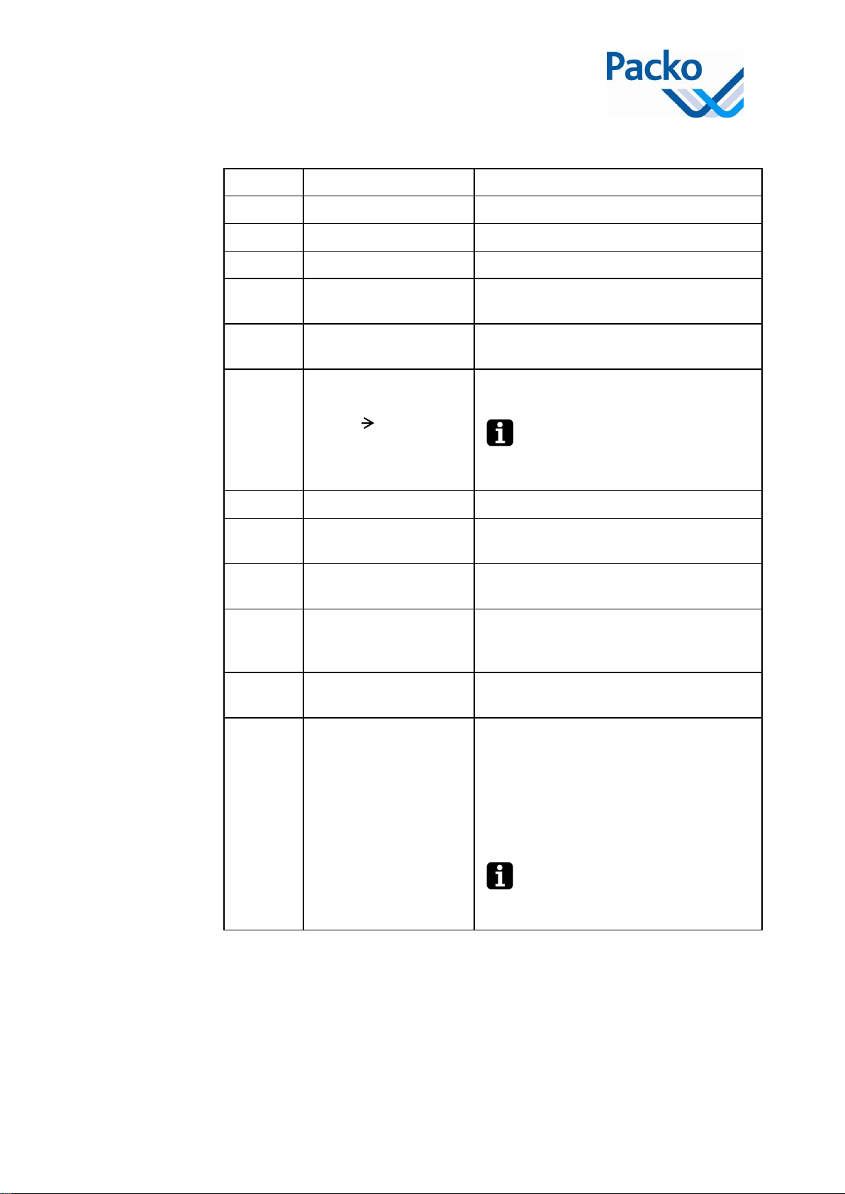
A number of icons are used in this manual, to draw your attention to, for example,
safety information. The table below provides an overview of the icons used and
what they mean:
Icon
Meaning
Description
Remark
A remark provides additional information about a
certain topic. The information in a remark is not
invaluable, but can be useful.
Attention!
If you do not follow the directions precisely, then:
The system can be damaged (in this case, damage
is not covered by the warranty)
The operation can be disturbed.
Warning!
A warning draws your attention to a possible danger
or risk of personal injury.
The procedures in this manual are broken down into numbered actions . These
actions have to be carried out in the described sequential order.
The company PACKO INOX N.V. reserves the right to make changes to the
manual at any time and without prior notice.
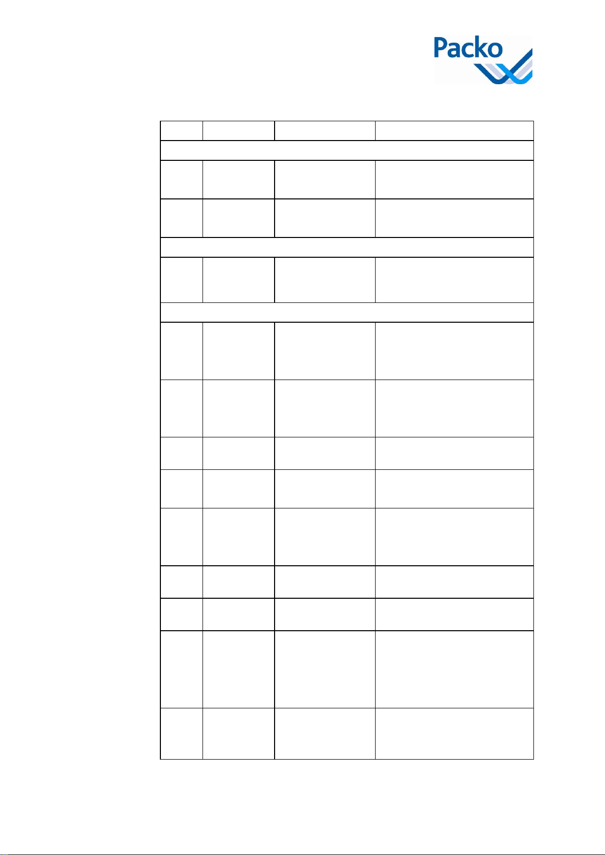
Introduction
In this manual
you will find …
Use of the icons
Procedures
Changes

Manual Packo Ice Builders 4
Safety instructions
Next to the safety instructions here below, always observe local regulations and
prescriptions.
The stickers below can be fixed on to your PIB to assure the safety of the use of
the tank. They cannot be removed according to the CE regulations:
Sticker
Instructions
The machine or part of it is built
according to the CE regulations.
You are invited to read the instructions.
Danger :
Machinery / equipment connected to
electrical network.
Do not spray water on the motor.
Do not spray water on the pump.
The operator needs to read this manual carefully before using the PIB.
Service or maintenance works should only be carried out by trained personnel.
Before doing the following, turn the main switch (located on the side of the
electrical control cabinet) to 0 or OFF and lock it:
Introduction
Stickers
Training of
operators
Maintenance &
fault finding
Electricity

Manual Packo Ice Builders 5
-Prior the opening the electrical cabinet of the PIB.
-Prior to any service work to the PIB or any of its components.
-In case of electrical or mechanical faults, inform the installer immediately.
-Prior to any work on the cooling system.
Make sure that your hands are dry when you use the buttons.
When you touch electronic equipment make sure you unload yourself of
static electricity.
Never spray water under high pressure at the PIB.
Wear protective gloves and safety goggles whilst cleaning the
equipment.
-Only use the PIB for its intended use which means the creation of ice
water.
-The PIB is not suitable for cooling other liquids then ice water.
-Do not put anything on the PIB.
Cleaning
General

Manual Packo Ice Builders 6
1. Equipment overview
The Packo Ice Builders (PIB) are compact and powerful units capable of storing
cooling energy in ice form and afterwards releasing this energy by generating ice
water for various cooling applications.
1
2
3
4
5
6
7
8
9
10
11

Manual Packo Ice Builders 7
Main parts and functions:
Element
Description
Function
1
Ice water reservoir
Insulated vessel to hold the ice water.
2
Insulated cover
Insulated cover for the ice water reservoir.
3
Electrical enclosure
Control system PIB.
4
Ice water pump
Supply the ice water to the cooling
application.
5
Cooling unit
Provide the required cooling capacity to the
evaporator.
6
Ice water
homogenisation
(PIB 25 370)
Ensure an even ice meltdown by injecting
air through the ice water reservoir.
The air blower is automatically
turned on when the ice water pump
is running.
7
Leg
Adjustment/levelling of the PIB
8
Evaporator
Cool / freeze the water in the ice water
reservoir.
9
Return header
Distribute the return (heated) water back
into the PIB.
10
Electronic ice thickness
sensors
Control the thickness of the ice layer
between the pre-set minimum and
maximum value.
11
Automatic ice water
level control
Maintains the ice water up the required
level.
12
Heat exchanger
(optional)
The heat exchanger provides cooling to a
secondary circuit and is available in the
following sizes:
-Type B28*46 (flow rate = 40l/min)
-Type B28*80 (flow rate = 60 l/min)
-Type B28*126 (flow rate = 100 l/min)
Type B28*126 is not possible with
PIB-8 and PIB-13

Manual Packo Ice Builders 8
2. Electrical control panel
Main
Switch
Cooling unit 2
Cooling unit 1

Manual Packo Ice Builders 9
#
Component
Tag
Function
Tension
Main
switch
Switch
Main Switch
0-1
Power equipment on / off
47H1
Lamp
Tension
Indicates when the PIB is on
(tension present). Main Switch.
Alarm
47H2
Lamp
Thermal Safety
compressor(s) and
air blower(s)
Indicates when the motor of
compressor(s), air blower(s) is
overloaded.
Cooling unit 1
26H1
Lamp
Tension
Ok
Main switch on Cooling unit 1
-0: off
-1: on
25S1
Switch
0 - 1
Control circuit Cooling unit 1
-0: off
-1: on
25S2
Knob
Boost function
cooling unit 1
-Push: built up once to
max. ice limits
25S3
Switch
Clock switch
cooling unit 1
-Auto: no clock is used
-Clock: Clock is used
25H1
Lamp
Cooling active
Liquid valve
-0: off
-1: on
26H3
Lamp
BP OK
On : when BP is closed and
Cooling is active
26H4
Lamp
HP Compressor 1
OK
On : when HP is closed and BP
is closed and cooling is active
26H6
Lamp
ThKa Compressor 1
OK
Indicates when compressor 1
(cooling unit 1) is running.
On : when ThKa is closed and
HP is closed and BP is closed
and cooling is active
26H5
Lamp
(Model
dependant)
HP Compressor 2
OK
On : when HP is closed and BP
is closed and cooling is active

Manual Packo Ice Builders 10
26H7
Lamp
(Model
dependant)
ThKa Compressor 2
OK
Indicates when compressor 2
(cooling unit 1) is running.
On : when ThKa is closed and
HP is closed and BP is closed
and cooling is active
Cooling unit 2-4 (Model dependant)
31H1
Lamp
Tension
Ok
Main switch on Cooling unit 2
-0: off
-1: on
30S1
Switch
0 –1
Control circuit Cooling unit 2
-0: off
-1: on
30S2
Knob
Boost function
cooling unit 1
-Push: built up once to
max. ice limits
30S3
Switch
Clock switch
cooling unit 1
-Auto: no clock is used
-Clock: Clock is used
30H1
Lamp
Cooling active
Liquid valve
-0: off
-1: on
31H3
Lamp
BP OK
On : when BP is closed and
Cooling is active
31H4
Lamp
HP Compressor 1
OK
On : when HP is closed and BP
is closed and cooling is active
31H6
Lamp
ThKa Compressor 1
OK
Indicates when compressor 1
(cooling unit 2) is running.
On : when ThKa is closed and
HP is closed and BP is closed
and cooling is active
31H5
Lamp
(Model
dependant)
HP Compressor 2
OK
On : when HP is closed and BP
is closed and cooling is active
31H7
Lamp
(Model
dependant)
ThKa Compressor 2
OK
Indicates when compressor 2
(cooling unit 2) is running.
On : when ThKa is closed and
HP is closed and BP is closed
and cooling is active
Ice water circuit
45S1
Switch
Ice water pump 1
M-0-A
-M: Manual operation
-0: Pump off
-A: Automatic
operation

Manual Packo Ice Builders 11
47H3
Lamp
Thermal Safety ice
water pump 1
Indicates when ice water pump 1
is overloaded.
45S2,
…
Switch
(model
dependant)
Ice water pump 2-8
M-0-A
-M: Manual operation
-0: Pump off
-A: Automatic
operation
47H4,
…
Lamp (Model
dependant)
Thermal Safety ice
water pump 2
Indicates when ice water pump 2
is overloaded.
Level control
55S1
Switch
Level control
M-A
-M: Manual operation
-A: Automatic
operation

Manual Packo Ice Builders 12
3. Start-up and normal use
3.1. Filling PIB
The Packo Ice Builder has to be filled with pure, clear water (drinking quality) up
to 1cm above the top copper tube of the evaporator.
The ice water reservoir may only be filled with water after the
cooling circuit has been made vacuum and put under pressure.
To protect the system an inhibitor must be added to the water before
the start-up.
The PIB can be filled automatically by following these steps:
Step
Action
1
Place the switch “Level control” in position A which will open the water
supply valve.
2
The filling cycle will automatically stop when the required level has been
reached.
3
Remove the cover.
4
Add the amount of 1, 2, 3-Benzotriazol needed to the ice water reservoir.
For the required dosage please check Manual for installation/ operation/
maintenance, chapter “4. Maintenance”.
5
Put the cover plate back in place.

Manual Packo Ice Builders 13
3.2. PIB operation
When starting up the PIB, proceed as indicated in the following table:
Step
Action
1
Turn on the power supply (main switch).
2
Turn on the cooling unit(s) (switches cooling units).
3
When the controls are ...
Then...
Manually
(the ice water pump is controlled by
the PIB)
Put the control switch in position
“M”.
Automatically
(the ice water pump is controlled by
an external source)
Put the control switch in position
“A”.
4
When the ice formation has reached the required level, the valve
controlling the flow of cooling agent is closed and the cooling units are
stopped.
During a prolonged period without ice building (cooling units are not
running), the cooling units can switch on and off for a short period.
5
Always leave the ice accumulator under tension to ensure proper control
of the ice capacity.
Table of contents