Panasonic EYFGB1N User manual

IMPORTANT
This manual contains safety information. Read manual completely before rst using this product and save this
manual for future use.
IMPORTANT
Ce manuel contient des informations de sécurité. Veuillez lire l'intégralité du manuel avant la première utilisation de
ce produit et conservez ce manuel pour les utilisations futures.
IMPORTANTE
Este manual tiene información de seguridad. Lea todo el manual antes de usar este producto por primera vez y
guarde el manual para poderlo consultar en el futuro.
Operating Instructions
Instructions d’utilisation
Manual de instrucciones
Cordless Screwdriver
Tournevis sans l
Destornillador inalámbrico
Model No: EYFGB1N
EYFGB2N
EYFGB3N

-
2
-
Index/Index/Indice
English: Page 4
Français: Page 14
Español: Página 25
FUNCTIONAL DESCRIPTION
DESCRIPTION DES FONCTIONS
DESCRIPCIÓN FUNCIONAL
Clutch setting handle and battery are not included.
La poignée de réglage de l'embrayage et la batterie ne sont pas incluses.
La empuñadura de ajuste de embrague y la batería no están incluidos.
(D)
(M)
(A)
(E)
(F)
(G)
(L)
(K)
(C)
(B)
(H)(I)
(J)

-
3
-
(A) 6.35 mm (1/4") hex quick connect chuck
Mandrin de connexion rapide hexagonal 6,35 mm
Mandril hexagonal de conexión rápida de 6,35 mm (B) Clutch shutter
Volet d'embrayage
Cierre del embrague
(C) Hole for tool hanger
Trou pour dispositif de suspension de l'outil
Oricio para el colgador de la herramienta (D) Tightening conrmation lamp
Témoin de conrmation de serrage
Lámpara de conrmación de apriete
(E) Forward/Reverse lever
Levier d’inversion marche avant/marche arrière
Palanca de avance/marcha atrás (F) Alignment mark
Marques d’alignement
Marcas de alineación
(G) Control panel
Panneau de commande
Panel de control (H) LED light on/off button
Bouton Marche/Arrêt de la lumière DEL
Botón ENCENDIDO/APAGADO de luz LED
(I) Battery indication lamp
Témoin indicateur de la batterie
Lámpara de indicadora de la batería (J) Display
Afchage
Visor
(K) LED light
Lumière DEL
Luz LED (L) Variable speed control trigger
Gâchette de commande de vitesse
Disparador del control de velocidad variable
(M) Clutch setting handle
Poignée de réglage de l'embrayage
Empuñadura de ajuste de embrague

-
4
-
EN EN
EN EN
I
.
GENERAL SAFETY
RULES
WARNING! Read all instructions
Failure to follow all instructions listed
below may result in electric shock, fire
and/or serious injury. The term “power
tool” in all of the warnings listed below
refers to your mains operated (corded)
power tool and battery operated
(cordless) power tool.
SAVE THESE INSTRUCTIONS
Work Area Safety
1) Keep work area clean and well lit.
Cluttered or dark areas invite accidents.
2)
Do not operate power tools in explosive
atmospheres, such as in the presence
of flammable liquids, gases or dust.
Power tools create sparks which may
ignite the dust or fumes.
3) Keep children and bystanders away
while operating a power tool.
Distractions can cause you to lose control.
Electrical Safety
1) Power tool plugs must match the
outlet. Never modify the plug in any
way. Do not use any adapter plugs
with earthed (grounded) power tools.
Unmodified plugs and matching outlets
will reduce risk of electric shock.
2) Avoid body contact with earthed or
grounded surfaces such as pipes,
radiators, ranges and refrigerators.
There is an increased risk of electric shock
if your body is earthed or grounded.
3) Do not expose power tools to rain or
wet conditions.
Water entering a power tool will increase
the risk of electric shock.
4) Do not abuse the cord. Never use
the cord for carrying, pulling or
unplugging the power tool. Keep
cord away from heat, oil, sharp edges
or moving parts.
Damaged or entangled cords increase
the risk of electric shock.
5)
When operating a power tool outdoors,
use an extension cord suitable for
outdoor use.
Use of a cord suitable for outdoor use
reduces the risk of electric shock.
Personal Safety
1)
Stay alert, watch what you are doing
and use common sense when operating
a power tool. Do not use a power tool
while you are tired or under the influence
of drugs, alcohol or medication.
A moment of inattention while operating
power tools may result in personal injury.
2) Use safety equipment. Always wear
eye protection.
Safety equipment such as dust mask,
non-skid safety shoes, hard hat, or
hearing protection used for appropriate
conditions will reduce personal injuries.
3) Avoid accidental starting. Ensure the
switch is in the off position before
plugging in.
Carrying power tools with your finger on
the switch or plugging in the power tools
that have the switch on invites accidents.
4) Remove any adjusting key or wrench
before turning the power tool on.
A wrench or a key left attached to a
rotating part of the power tool may result
in personal injury.
5) Do not overreach. Keep proper
footing and balance at all times.
This enables better control of the power
tool in unexpected situations.
6) Dress properly. Do not wear loose
clothing or jewellery. Keep your
hair, clothing and gloves away from
moving parts.
Loose clothes, jewellery or long hair can
be caught in moving parts.
7) If devices are provided for the
connection of dust extraction and
collection facilities, ensure these are
connected and properly used.
Use of these devices can reduce dust
related hazards.
Power Tool Use and Care
1)
Do not force the power tool. Use the
correct power tool for your application.
The correct power tool will do the job
better and safer at the rate for which it
was designed.
2) Do not use the power tool if the
switch does not turn it on and off.
Any power tool that cannot be controlled
with the switch is dangerous and must
be repaired.
3) Disconnect the plug from the power
source and/or the battery pack from

EN EN
-
5
-
EN EN
the power tool before making any
adjustments, changing accessories,
or storing power tools.
Such preventive safety measures
reduce the risk of starting the power tool
accidentally.
4)
Store idle power tools out of the reach
of children and do not allow persons
unfamiliar with the power tool or these
instructions to operate the power tool.
Power tools are dangerous in the hands
of untrained users.
5) Maintain power tools. Check for
misalignment or binding of moving
parts, breakage of parts and any other
condition that may affect the power
tools operation. If damaged, have the
power tool repaired before use.
Many accidents are caused by poorly
maintained power tools.
6) Keep cutting tools sharp and clean.
Properly maintained cutting tools with
sharp cutting edges are less likely to
bind and are easier to control.
7) Use the power tool, accessories
and tool bits etc. in accordance with
these instructions and in the manner
intended for the particular type of
power tool, taking into account the
working conditions and the work to
be performed.
Use of the power tool for operations
different from those intended could
result in a hazardous situation.
Battery Tool Use and Care
1) Ensure the switch is in the off position
before inserting battery pack.
Inserting battery pack into power tools
that have the switch on invites accidents.
2) Recharge only with the charger
specified by the manufacturer.
A charger that is suitable for one type
of battery pack may create a risk of fire
when used with another battery pack.
3) Use power tools only with specifically
designated battery packs.
Use of any other battery packs may
create a risk of injury and fire.
4)
When battery pack is not in use, keep it
away from other metal objects like paper
clips, coins, keys, nails, screws, or other
small metal objects that can make a
connection from one terminal to another.
Shorting the battery terminals together
may cause burns, or a fire.
5) Under abusive conditions, liquid may
be ejected from battery; avoid contact.
If contact accidentally occurs, flush
with water. If liquid contacts eyes,
additionally seek medical help.
Liquid ejected from the battery may
cause irritation or burns.
Service
1) Have your power tool serviced by a
qualified repair person using only
identical replacement parts.
This will ensure that the safety of power
tool is maintained.
II
.INTENDED USE
This tool is a Cordless Screwdriver and can
be used to tighten bolts, nuts, and screws with
torque control.
III
.
ADDITIONAL
SAFETY RULES
1
) Wear ear protectors when using the
tool for extended periods.
2) Be aware that this tool is always in an
operating condition, since it does not have
to be plugged into an electrical outlet.
3) Hold power tools by insulated gripping
surfaces when performing an operation
where the cutting tool may contact hid-
den wiring or its own cord.
Contact with a “live” wire will make exposed
metal parts of the tool “live” and shock the
operator.
4) Do NOT operate the Forward/Reverse
lever when the main switch is on. The bat-
tery will discharge rapidly and damage to
the unit may occur.
5) During charging, the charger may become
slightly warm. This is normal.
Do NOT charge the battery for a long period.
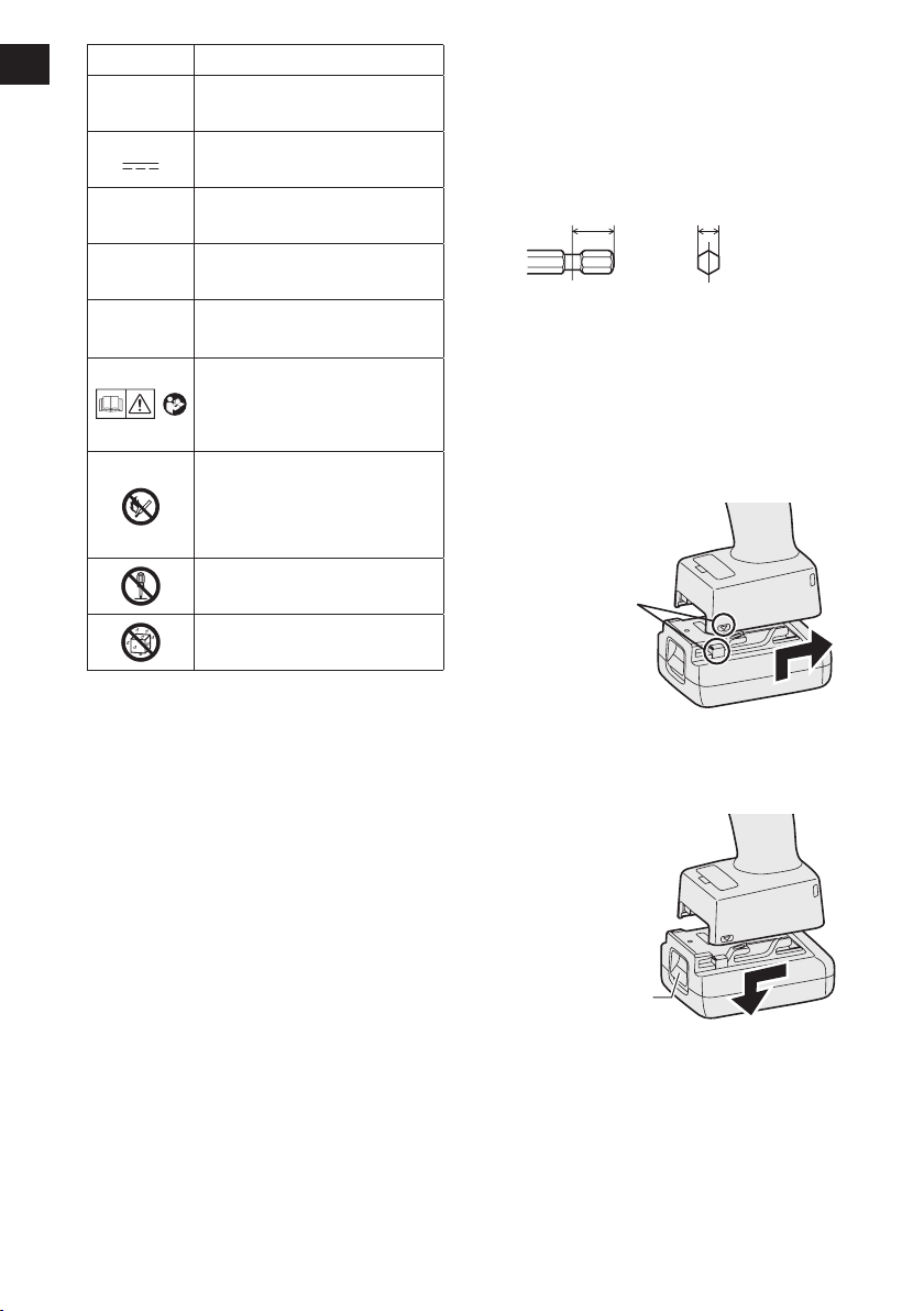
6) When storing or carrying the tool, set the
Forward/Reverse lever to the center posi-
tion (switch lock).
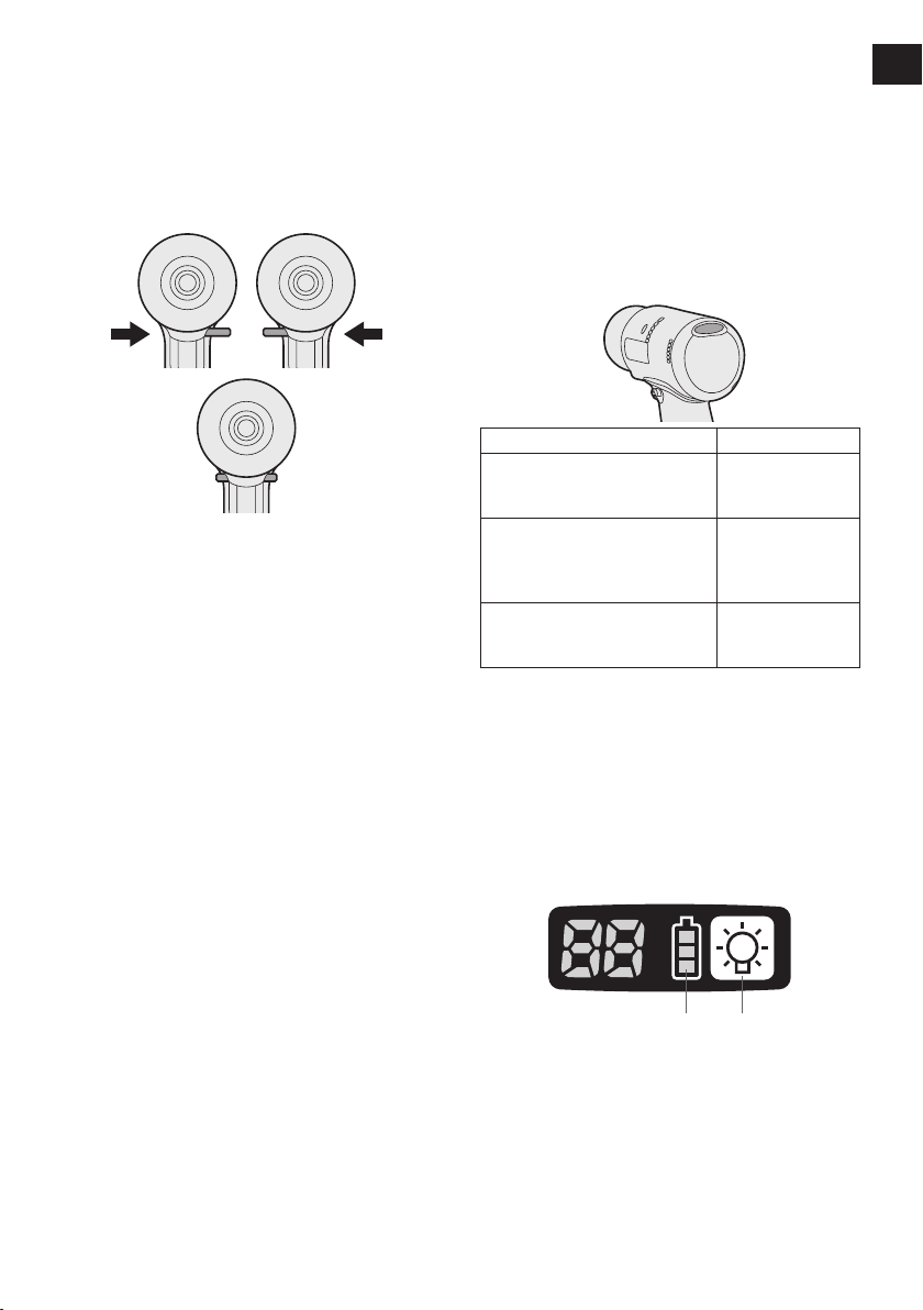
7) Do not strain the tool by holding the speed
control trigger halfway (speed control
mode) so that the motor stops.

-
6
-
EN EN
EN EN
Symbol Meaning
VVolts
Direct current
n0No load speed
… min-1 Revolutions or
reciprocations per minutes
Ah Electrical capacity of battery
pack
To reduce the risk of
injury, user must read and
understand instruction
manual.
Do not incinerate or heat
battery pack. Do not charge
or use under conditions of
high temperature. Do not ex-
pose to high temperatures.
Do not disassemble or
modify.
Do not expose to rain or
water.
IV
.ASSEMBLY
Attaching or Removing Bit
NOTE:
•
When attaching or removing a bit, discon-
nect battery pack from tool or place the
switch in the center position (switch lock).
1. Hold the collar of quick connect chuck and
pull it out from the tool.
2. Insert the bit into the chuck. Release the
collar.
3. The collar will return to its original position
when it is released.
4.
Pull the bit to make sure it does not come out.
5. To remove the bit, pull out the collar in the
same way.
CAUTION:
• If the collar does not return to its origi-
nal position or the bit comes out when
pulled on, the bit has not been properly
attached. Make sure the bit is properly
attached before use.
9 mm – 13 mm
(23/64" – 33/64")
6.35 mm
(1/4")
Attaching or Removing Bat-
tery Pack
1. To connect the battery pack:
Align the highlighted marker points and
attach battery pack.
• Slide the battery pack until it locks into
position.
Alignment
marks
2. To remove the battery pack:
Push down the button and slide the battery
pack forward.
Button

EN EN
-
7
-
EN EN
V.
OPERATION
[Main Body]
Switch and Forward/Reverse
Lever Operation
Forward Reverse
Switch lock
CAUTION:
To prevent damage, do not operate
Forward/Reverse lever until the bit comes
to a complete stop.
Forward Rotation Switch
Operation
1. Push the lever for forward rotation.
2. Depress the trigger switch slightly to start
the tool slowly.
3. The speed increases with the amount of
depression of the trigger for efficient tight-
ening of screws. The brake operates and
the bit stops immediately when the trigger
is released.
4. After use, set the lever to its center posi-
tion (switch lock).
Reverse Rotation Switch
Operation
1.
Push the lever for reverse rotation. Check
the
direction of rotation before use.
2.
Depress the trigger switch slightly to start the
tool slowly.
3. After use, set the lever to its center posi-
tion (switch lock).
CAUTION:
• To eliminate excessive temperature
increase of the tool surface, do not
operate the tool continuously using two
or more battery packs. Tool needs cool
off time before switching to another
pack.
Tightening confirmation lamp
• The tightening confirmation lamp can be
used to check whether tightening has been
completed properly.
Tool status Lamp display
Tightening complete
(Normal clutch operation)
Green
(For approx. 2
seconds)
• Tightening not complete
• Tightening complete
without fullling the set
function conditions
Red
(For approx. 2
seconds)
The automatic power-
off function has been
activated.
Red
(For approx. 5
minutes)
NOTE
• The tightening confirmation lamp will
not turn on under the following condi-
tions:
• During reverse rotation operation
• The lamp turns off when the tool is in
operation.
Control Panel
(1) (2)
(1) The battery indication lamp
• Use the battery indication lamp to check
how much power is left in the battery.
• Battery life varies slightly with ambient tem-
perature and battery characteristics. The
lamp is designed to provide a rough indica-
tion of remaining battery life.

-
8
-
EN EN
EN EN
Indicator Battery status
Fully charged
Approx. 40% or less
remaining
Flashing
Flashing
Approx. 20% or less
remaining (indicates need
to recharge battery)
The battery pack will need
to be charged soon.
Flashing
No charge
The battery pack needs to
be charged.
(The tool’s automatic
power-off function will
activate at this stage.)
Automatic power-off function
• The automatic power-off function is designed
to prevent a loss of tightening torque due to
reduced battery voltage. Once it has been
activated, the tool will not operate until the
battery pack has been charged (or replaced
with a fresh unit), even if the trigger is
depressed.
NOTE:
• All 3 bars on the battery indication lamp
will flash when the automatic power-off
function is activated.
• When the battery indication lamp begins
flashing, the battery pack should be
charged (or replaced with a fresh unit)
immediately.
• Be sure to fully charge the battery pack
in question after activation of the auto-
matic power-off function. Failure to do
so may prevent the automatic power-off
function from being properly deactivated.
• The tool may power off automatically
under heavy work loads.
However the tool will be operational
again after the battery is removed and
reinstalled. The battery must have a
sufficient charge to re-enable the tool.
(2) LED light
Pressing the button toggles the LED light on
and off.
The light consumes very little power and will
not significantly affect battery run time.
CAUTION:
• The built-in LED light is designed to illu-
minate the small work area temporarily.
•
Do not use it as a substitute for a regu-
lar
flashlight, since it does not have
enough brightness
.
This tool has the built-in LED light.
Caution: DO NOT STARE INTO BEAM.
Use of controls or adjustments or performance
of procedures other than those specied herein
may result in hazardous radiation exposure.

EN EN
-
9
-
EN EN
Tightening Torque Setting
1. Open the shutter with the clutch setting
handle.
Shutter (closed)
Front view of the
main unit
Clutch setting handle
(short side view)
Engage the ribs on the main unit with the
ribs on the clutch setting handle (on the
short side) and turn clockwise.
2. Insert the 3 ribs on clutch setting handle
(on the long side) into the shutter holes.
Make sure to insert the wider rib into big-
ger hole.
Bigger hole Wider rib
To set clutch torque, turn the clutch setting
handle clockwise or counterclockwise.
Clutch stage can be set from 1 to 60 stage.
(two full turns)
Decrease torque
Increase torque
Example-clutch
setting #40
Example-clutch
setting #20
3. Close the shutter with the clutch setting
handle by turning counterclockwise.
NOTE:
• Be sure to close the shutter to prevent
dust.
Tightening torque chart (reference
values)
This data consists of reference values measured
under the conditions described below. During
actual work, values will vary based on operating
conditions (lock bolt, target substrate, method
of securing the bolt in place, etc.).
Measurement conditions
As dened by Panasonic
0
2
4
6
8
10
12
(53.1)
(106.2)
(in·lbs)
1 10 3020 40 50 60
Nm
EYFGB3
EYFGB2
EYFGB1
Torque setting level
CAUTION:
• Always check the tool’s tightening
torque before use. Improper tool opera-
tion may result in excessive or inad-
equate tightening.
• Always operate the tool with the switch
fully depressed.
•
The torque accuracy may not be stable if
the switch is not sufficiently depressed.
•
Use figures from the tightening torque
chart to guide your selection of torque
clutch setting. (See the tightening torque
chart)

-
10
-
EN EN
EN EN
Error Display
In the event of a tool or battery pack malfunction, the control panel will display an error message.
Please check the tool or battery pack as described in the following chart before having them
serviced.
Display Likely cause Corrective action
The battery pack is too hot. Stop work and allow the battery
pack to cool before resuming use
of the tool.
The tool is too hot to operate. Stop work and allow the tool to
cool before resuming use.
The contacts that connect the
battery pack and tool are dirty. Remove any dirt.
The battery pack has not been
properly inserted into the tool. Insert the battery pack rmly into
the tool.
The pins on either the tool or
battery pack have worn down. Replace the battery pack.
Motor failure, etc. Stop using the tool immediately.
Tool circuit malfunction, failure,
etc.

EN EN
-
11
-
EN EN
[Battery Pack]
For Appropriate Use of Bat-
tery Pack
Li-ion Battery Pack
• For optimum battery life, store the Li-ion bat-
tery pack following use without charging it.
• When charging the battery pack, confirm
that the terminals on the battery charger
are free of foreign substances such as dust
and water etc. Clean the terminals before
charging the battery pack if any foreign sub-
stances are found on the terminals.
The life of the battery pack terminals may be
affected by foreign substances such as dust
and water etc. during operation.
• When battery pack is not in use, keep it
away from other metal objects like: paper
clips, coins, keys, nails, screws, or other
small metal objects that can make a con-
nection from one terminal to another.
Shorting the battery terminals together may
cause sparks, burns or a fire.
• When operating the battery pack, make sure
the work place is well ventilated.
• When the battery pack is removed from the
main body of the tool, replace the battery
pack cover immediately in order to prevent
dust or dirt from contaminating the battery
terminals and causing a short circuit.
Battery Pack Life
The rechargeable batteries have a limited life.
If the operation time becomes extremely short
after recharging, replace the battery pack with
a new one.
Battery Recycling
ATTENTION:
A Li-ion battery that is recyclable powers
the product you have purchased.
Please call 1-800-8-BATTERY for infor-
mation on how to recycle this battery.
[Battery Charger]
Charging
Read the operating manual for Panasonic bat-
tery charger for the battery pack before charg-
ing.
Before charging the bat-
tery
Charge the battery at a temperature of 5°C
(41°F) to 40°C (104°F).
The battery pack cannot be charged at a
tem perature of less than 5°C (41°F). If the
temperature of the battery pack is less than
5°C (41°F), rst remove the battery pack from
the charger and allow it to sit for an hour in a
location where the temperature is 5°C (41°F)
or warmer. Then charge the battery pack
again.
VI.
MAINTENANCE
Use only a dry, soft cloth for wiping the unit.
Do not use a damp cloth, thinner, benzine, or
other volatile solvents for cleaning.

-
12
-
EN EN
EN EN
Protector for battery
• EYFA04-H
• EYFA06-H
Clutch setting handle
• EYFA32
Tool hanger
• EYFA40
CAUTION:
Tool hanger is for balancer use only.
Excessive force or impact might break it and
the main unit might fall off.
VIII
.SPECIFICATIONS
NOTE:
Weight indication
Greater than or equal to 1kg : indicated by 0.05kg.
Less than 1kg : indicated by 0.01kg.
MAIN UNIT
Model EYFGB1 EYFGB2 EYFGB3
N NR N NR N NR
Motor 14.4 V DC
Chuck
size
Single-ended 9.5-13 mm (3/8"-33/64")
Double-ended 12-16 mm (15/32"-5/8")
No load speed (Stage) 0-800 (80) 0-750 (75) 0-450 (45)
Torque adjustment
range
2-5.5 N·m
(0.20-0.56 kgf·m,
17.70-48.68 in·lbs)
5-8 N·m
(0.51-0.82 kgf·m,
44.25-70.81 in·lbs)
5-10 N·m
(0.51-1.02 kgf·m,
44.25-88.51 in·lbs)
Number of torque set-
ting levels
60
(In approx. 0.08 N·m
increments)
60
(In approx. 0.08 N·m
increments)
60
(In approx. 0.13 N·m
increments)
Overall length 199 mm (7-53/64")
Weight (with battery
pack: EYFB41) 1.25 kg (2.76 lbs) 1.3 kg (2.87 lbs)
Weight (with battery
pack: EYFB42) 1.5 kg (3.31 lbs) 1.5 kg (3.31 lbs)
CAUTION:
Always check the tool’s tightening torque before use.
Improper tool operation may result in excessive or inadequate tightening.
NOTE:
Number of torque setting levels
Though the torque setting level of clutch handle may exceed 60 levels, please set the level up
to 60 levels.
VII
.ACCESSORIES
Charger
• EY0L82
Battery pack
• EYFB41
• EYFB42
Protector for tool
• EYFA05-A (Blue)
• EYFA05-Y (Yellow)
• EYFA05-H (Gray)

EN EN
-
13
-
EN EN
BATTERY PACK (not included with shipment)
Model EYFB41 EYFB42
Storage battery Li-ion battery
Battery voltage 14.4 V DC (3.6 V/4 cells) 14.4 V DC (3.6 V/8 cells)
BATTERY CHARGER (not included with shipment)
Model EY0L82
Rating See the rating plate on the bottom of the charger.
Weight 0.93 kg(2.05 lbs)
Charging time EYFB41
Usable: 35 min.
Full: 40 min.
EYFB42
Usable: 50 min.
Full: 60 min.

-
14
-
FR FR
FR FR
I
.
CONSIGNES DE SECU-
RITE GENERALES
AVERTISSEMENT! Veuillez lire tou-
tes les instructions.
Si les instructions détaillées ci-dessous ne sont
pas observées, cela peut entraîner une électro-
cution, un incendie et/ou des blessures graves.
Le terme “outil mécanique” utilisé dans tous les
avertissements ci-dessous se réfère aux outils
mécaniques opérés par cordons d'alimentation
et par batterie (sans l).
CONSERVEZ CES INSTRUC-
TIONS
Sécurité de la zone de travail
1) Gardez la zone de travail propre et
bien aérée.
Les endroits encombrés et sombres invi-
tent les accidents.
2) Ne faites pas fonctionner les outils
mécaniques dans des atmosphères
explosives, comme en présence de
liquides inammables, de gaz ou de
poussière.
Les outils mécaniques génèrent des étin-
celles qui peuvent enflammer la poussiè-
re ou les vapeurs.
3) Gardez les enfants et les spectateurs
éloignés lors du fonctionnement d’un
outil mécanique.
Les distractions peuvent en faire perdre le
contrôle.
Sécurité électrique
1) La fiche des outils mécaniques doit
correspondre aux prises secteur. Ne
modifiez la fiche sous aucun prétexte.
N’utilisez pas de fiche adaptatrice
avec les outils mécaniques mis à la
terre.
Des fiches non modifiées et des prises
secteur correspondant réduisent les
risques d’électrocution.
2) Evitez tout contact physique avec les
surfaces mises à la terre telles que
tuyaux, radiateurs, micro-ondes et
réfrigérateurs.
Il y a un risque d’électrocution supplémen-
taire si votre corps est mis à la terre.
3) N’exposez pas les outils mécaniques à
la pluie ou à des conditions humides.
De l’eau pénétrant dans un outil mécani-
que augmente le risque d’électrocution.
4) Ne malmenez pas le cordon. N’utilisez
jamais le cordon pour transporter,
pour tirer ou pour débrancher l’outil
mécanique. Gardez le cordon éloigné
de la chaleur, de l’huile, d’objets aux
bords coupants ou de pièces en
mouvement.
Les cordons endommagés on emmêlés
augmentent le risque d'électrocution.
5)
Lors du fonctionnement des outils méca-
niques à l
’
extérieur, utilisez une rallonge
adaptée à l
’
utilisation à l
’
extérieur.
L’utilisation d’un cordon adapté à l’utilisa-
tion à l’extérieur réduit les risques d’élec-
trocution.
Sécurité personnelle
1) Restez alerte, regardez ce que vous
faites et faites preuve de bon sens
lorsque vous utilisez un outil méca-
nique. N’utilisez pas un outil méca-
nique alors que vous êtes fatigué ou
sous les effets de drogue, d’alcool ou
de médicaments.
Un moment d’inattention pendant que
vous faites fonctionner l’outil mécanique
peut entraîner des blessures graves.
2) Utilisez des équipements de sécurité.
Portez toujours des protection pour
vos yeux.
Des équipements de sécurité comme
masque antipoussière, chaussures
de sécurité non glissantes, casque de
protection ou protections d’oreilles,
utilisés dans des conditions appropriées
réduisent les blessures corporelles.
3) Evitez tout démarrage accidentel.
Assurez-vous que l’interrupteur est
en position d'arrêt avant de brancher
l’outil.
Le transport d’outils mécaniques avec le
doigt sur l’interrupteur ou le branchement
d’outils mécaniques dont l’interrupteur
est sur la position de marche invite les
accidents.
4) Retirez toute clé d’ajustement ou
clé de serrage avant de mettre l’outil
mécanique en marche.
Une clé de serrage ou une clé d’ajuste-
ment laissée attachée à une pièce
tournante de l’outil mécanique peut
entraîner des blessures corporelles.
5) Ne vous mettez pas en déséquilibre.
Gardez une bonne prise au sol et votre
équilibre à tout moment.
Ceci permet un meilleur contrôle de l’outil
mécanique dans des situations inatten-
dues.

FR FR
-
15
-
FR FR
6) Habillez-vous correctement. Ne portez
pas de vêtements lâches ou de bijoux.
Gardez vos cheveux, vêtements et
gants éloignés des pièces en mouve-
ment.
Des vêtements lâches, des bijoux ou
des cheveux longs peuvent se faire
prendre dans les pièces en mouvement.
7) Si des dispositifs pour la connexion
d’appareils d’extraction et de ramas-
sage de la poussière sont fournis,
assurez-vous qu’ils sont connectés et
correctement utilisés.
L’utilisation de ces dispositifs peut réduire
les risques concernés.
Utilisation et soins de l’outil méca-
nique
1)
Ne forcez pas l’outil mécanique. Utilisez
l’outil mécanique correct pour votre
application.
L’outil mécanique correct exécute mieux
le travail dans de meilleurs conditions
de sécurité s’il est utilisé à l’allure pour
laquelle il a été conçu.
2) N’utilisez pas l’outil mécanique si l’inter-
rupteur ne le met pas en marche ou ne
l’arrête pas.
Tout outil mécanique qui ne peut pas
être contrôlé par son interrupteur est
dangereux et doit être réparé.
3) Débranchez la fiche de la source d’ali-
mentation et/ou du bloc de batterie
avant d’effectuer tout ajustement, de
changer d’accessoire ou de ranger
l’outil mécanique.
De telles mesures de sécurité préventives
réduisent les risques de faire démarrer
l’outil mécanique accidentellement.
4)
Rangez les outils mécaniques inuti-
lisés hors de la portée des enfants
et ne laissez personne qui n’est pas
familiarisé avec l’outil mécanique ou
ses instructions faire fonctionner l’outil
mécanique.
Les outils mécaniques sont dangereux
dans les mains des utilisateurs manquant
d’entraînement.
5) Entretenez bien les outils mécaniques.
Vérifiez l’alignement ou l’emboîtage
des pièces en mouvement, l’intégrité
des pièces et toute autre condition
pouvant affecter le fonctionnement de
l’outil mécanique. S’il est endommagé,
faites réparer l’outil mécanique avant
de l’utiliser.
De nombreux accidents sont provoqués
par des outils mécaniques mal entre-
tenus.
6) Maintenez les outils de coupe affûtés
et propres.
Les outils de coupe bien entretenus
avec des lames bien affûtées ont moins
de chances de gripper et sont plus
faciles à contrôler.
7) Utilisez l’outil mécanique, les acces-
soires, les mèches, etc., conformément
à ces instructions et de la façon pour
laquelle l’outil particulier a été conçu
en tenant compte des conditions de
travail et de la tâche à exécuter.
L’utilisation de l’outil mécanique à des
fins autres que celles pour lesquelles
il a été conçu peut présenter une situa-
tion à risque.
Utilisation et soins de la batterie
de l’outil
1) Assurez-vous que l’interrupteur est
dans la position d’arrêt avant d’insérer
le bloc de batterie.
L’insertion du bloc de batterie dans un
outil mécanique dont l’interrupteur est
sur la position de marche peut provoquer
des accidents.
2) N’effectuez la recharge qu’avec le
chargeur spécifié par le fabricant.
Un chargeur convenant à un bloc de bat-
terie peut entraîner un risque d’incendie
lorsqu’un autre bloc de batterie est
utilisé.
3) N’utilisez les outils mécaniques
qu’avec les bloc de batterie spéciale-
ment conçus pour eux.
L’utilisation de tout autre bloc de bat-
terie peut entraîner un risque de bles-
sure et d’incendie.
4)
Lorsqu’un bloc de batterie n’est pas
utilisé, gardez-le éloigné d’objets métal-
liques comme agrafes, pièces de mon-
naie, clés, clous, vis ou tout autre petit
objet métallique pouvant établir une
connexion entre les deux bornes.
Si les bornes de la batterie sont mises
en court-circuit, cela peut entraîner des
brûlures ou un incendie.
5) Si elle est malmenée, du liquide peut
s’échapper de la batterie. Evitez tout
contact. Si un contact accidentel se
produit, rincez à l’eau. Si du liquide
entre en contact avec les yeux, con-
sultez un médecin.

-
16
-
FR FR
FR FR
Le liquide éjecté de la batterie peut
entraîner des irritations ou des brûlures.
Réparation
1) Faites réparer votre outil mécanique
par du personnel de réparation quali-
fié en n’utilisant que des pièces de
rechange identiques.
Ceci assure le maintien de la sécurité
de l’outil mécanique.
II
.
UTILISATION PREVUE
Cet outil est un tournevis sans l pouvant être
utilisé pour serrer des boulons, des écrous et
des vis, avec contrôle du couple de serrage.
III
.
RÈGLES DE SÉCURITÉ
SUPPLÉMENTAIRES
1) Porter des protèges-oreilles lors de
l’utilisation de l’outil pendant des pério-
des prolongées.
2) N’oubliez pas que cet appareil est toujours
prêt à fonctionner, parce qu’il ne doit pas
être branché dans une prise électrique.
3) Tenez les outils électriques grâce aux
surfaces antidérapantes isolées quand
vous travaillez avec quand un outil de
coupe peut entrer en contact avec des
câbles cachés ou son propre câble
d'alimentation.
Le contact avec un câble “à nu” fera explo-
ser les pièces métalliques de l'outil “à nu”
et l'utilisateur subira un choc.
4)
NE manœuvrez PAS le levier d’inversion
marche avant-marche arrière lorsque le
commutateur principal est sur la position de
marche. La batterie se déchargerait rapide-
ment et cela peut endommager l’unité.
5) Pendant le chargement, le chargeur peut
devenir légèrement chaud. Cela est nor-
mal.
NE chargez PAS la batterie pendant une
longue période.
6) Lorsque vous rangez ou transportez l’outil,
mettez le levier d’inversion marche avant
- marche arrière sur la position centrale
(verrouillage du commutateur).
7) Ne forcez pas l’outil en maintenant la
gâchette de contrôle de vitesse enfoncée
à moitié (mode de contrôle de la vitesse)
de sorte que le moteur s’arrête.
Symbole Signication
VVolts
Courant continu
n0Pas de vitesse de charge
… min-1 Tours ou mouvements
alternatifs par minute
Ah Capacité électrique de la
batterie autonome
Pour réduire les risques de
blessure, l'utilisateur doit lire
et comprendre le manuel
d'utilisation.
N’incinérez pas ni ne
chauffer le bloc de batterie.
Ne pas utiliser ni charger en
condition de température
élevée. Ne pas exposer à
des températures élevées.
Ne pas démonter ni modier.
Ne pas exposer à la pluie ni
à l'eau.
IV
.ASSEMBLAGE
Fixation ou retrait d’une
mèche
REMARQUE :
• Lors de l’installation ou de l’enlèvement
d’une mèche, débranchez la batterie
autonome de l’outil ou placez le commu-
tateur sur la position centrale (verrouilla-
ge du commutateur).
1. Maintenez le collier du mandrin de
connexion rapide et retirez-le de l’outil.
2. Insérez la mèche dans le mandrin. Relâ-
chez le collier.
3. Le collier reviendra dans sa position d’ori-
gine lorsqu’il sera relâché.
4. Tirez sur la mèche pour vérifier qu’elle ne
ressort pas.
5. Pour retirer la mèche, tirez le collier vers
l’extérieur de la même manière.

FR FR
-
17
-
FR FR
MISE EN GARDE :
• Si le collier ne revient pas dans sa posi-
tion d’origine ou si la mèche ressort lors-
que vous tirez dessus, cela signifie que
la mèche n’a pas été fixée correctement.
Assurez-vous que la mèche est bien
fixée avant toute utilisation.
9 mm – 13 mm
(23/64" – 33/64")
6.35 mm
(1/4")
Fixation ou retrait de la bat-
terie autonome
1. Pour raccorder la batterie autonome :
Alignez les points de marqueurs mis en
avant et attachez la batterie autonome.
• Faites glisser la batterie autonome jus-
qu’à ce qu’elle se verrouille en position.
Marques
d’alignement
2. Pour retirer la batterie autonome :
Poussez le bouton vers le bas et faites
glisser le bloc batterie en avant.
Bouton
V.
FONCTIONNEMENT
[Corps principal]
Utilisation du commutateur
et du levier d’inversion mar-
che avant-marche arrière
Rotation en
sens normal
Rotation en
sens inverse
Verrouillage de commutateur
MISE EN GARDE :
Pour prévenir tout dégât, n’actionnez pas
le levier d’inversion marche avant-mar-
che arrière tant que la mèche n’a pas
complètement terminé de tourner.
Utilisation du commutateur
pour une rotation en sens
normal
1. Poussez le levier pour obtenir une rotation
en sens normal.
2. Appuyez légèrement sur la gâchette pour
que l’outil commence à tourner lentement.
3. La vitesse augmente à mesure où la
gâchette est enfoncée pour un vissage
efficace des vis. Le frein fonctionne et la
mèche s’arrête immédiatement dès que la
gâchette est relâchée.
4. Ramenez le levier en position centrale
lorsque vous n’utilisez plus l’outil (ver-
rouillage du commutateur).

-
18
-
FR FR
FR FR
Utilisation du commutateur
de rotation en sens inverse
1. Poussez le levier pour obtenir une rotation
en sens inverse. Vérifiez le sens de rota-
tion avant d'utiliser l'outil.
2. Appuyez légèrement sur la gâchette pour
que l’outil commence à tourner lentement.
3. Ramenez le levier en position centrale
lorsque vous n’utilisez plus l’outil (ver-
rouillage du commutateur).
MISE EN GARDE :
• Pour empêcher toute élévation exces-
sive de la température de la surface
de l’outil, n'utilisez pas l'outil de façon
continue en utilisant deux batteries
autonomes ou plus. L’outil a besoin de
se refroidir pendant un certain temps
avant d'être connecté à une autre bat-
terie autonome.
Témoin de confirmation de serrage
• Le témoin de confirmation de serrage peut
être utilisé pour vérifier si le serrage a été
fait correctement.
État de l’outil Afchage du
témoin
Serrage terminé
(Fonctionnement normal
de l'embrayage)
Vert
(Pendant
environ 2
secondes)
• Serrage non terminé
• Serrage terminé sans
remplir les conditions de
fonction établies.
Rouge
(Pendant
environ 2
secondes)
La fonction d’arrêt
automatique a été activée.
Rouge
(Pendant
environ 5
minutes)
REMARQUE
• Le témoin de confirmation de serrage
ne s’allume pas dans les conditions sui-
vantes :
• Pendant le fonctionnement en rotation
inverse
• Le témoin s’éteint lorsque l’outil fonc-
tionne.
Panneau de commande
(1) (2)
(1) Témoin indicateur de la batterie
• Utilisez le témoin indicateur de la batterie
pour vérifier la quantité de charge restant
dans la batterie.
• La durée de vie de la batterie varie légère-
ment en fonction de la température ambian-
te et des caractéristiques de la batterie. Le
témoin est conçu pour fournir une indication
approximative de la durée de vie restante
de la batterie.
Indicateur État de la batterie
Pleinement chargée
Environ 40% ou moins
restant
Clignotant
Clignotant
Environ 20% ou moins
restant (indique le besoin
de recharger la batterie)
La batterie autonome va
bientôt avoir besoin d’être
chargée.
Clignotant
Pas de charge
La batterie autonome à
besoin d’être chargée.
(A ce stage, la fonction
d’arrêt automatique de
l’outil s’active.)
Fonction d’arrêt automatique
• La fonction d’arrêt automatique est conçue
pour empêcher une perte de couple de ser-
rage à la suite d’une tension réduite de la
batterie. Une fois activée, l’outil ne répondra
pas tant que la batterie n’aura pas été char-
gée (ou remplacée par une unité chargée),
même si la détente est pressée.
REMARQUE :
• Les 3 barres du témoin indicateur de la
batterie clignotent lorsque la fonction
d’arrêt automatique est activée.

FR FR
-
19
-
FR FR
• Lorsque le témoin indicateur de la bat-
terie se met à clignoter, il faut immé-
diatement charger la batterie autonome
(ou la remplacer par une unité char-
gée).
• Veillez à charger complètement la bat-
terie autonome en question après l’ac-
tivation de la fonction d’arrêt automa-
tique. Si cela n’est pas effectué, cela
peut empêcher la fonction d’arrêt auto-
matique d’être correctement désacti-
vée.
• L'outil peut s'éteindre automatiquement
sous des charges de travail lourdes.
Cependant l'outil sera de nouveau opé-
rationnel après le retrait et le rempla-
cement de la batterie. La batterie doit
avoir été suffisamment rechargée pour
redémarrer l'outil.
(2) Lumière DEL
Appuyez sur pour allumer et éteindre la
lumière DEL.
La lumière ne consomme que peu d'énergie
et n'affectera pas significativement la durée de
la batterie.
MISE EN GARDE :
• La lumière DEL incorporée est conçue
pour éclairer temporairement la petite
zone de travail.
• Ne l’utilisez pas comme remplacement
d’une torche normale, elle n’est pas
assez lumineuse.
Cet outil dispose d'une lumière DEL inté-
grée.
Mise en garde : NE REGARDEZ PAS
DIRECTEMENT LE FAISCEAU.
L’utilisation de commandes ou de réglages ou
l’exécution de procédures autres que ceux spé-
ciés dans ce manuel peut entraîner l’exposi-
tion à de dangereuses radiations.
Réglages du couple de
serrage
1. Ouvrez le volet avec la poignée de régla-
ge de l'embrayage.
Volet (fermé)
Vue frontale
de l'unité principale
Poignée de réglage de
l'embrayage (vue du
côté court)
Connectez les nervures de l'unité principa-
le avec celles de la poignée de réglage de
l'embrayage (sur le côté court) et tournez
dans le sens des aiguilles d'une montre.
2. Insérez les 3 nervures dans la poignée de
réglage de l'embrayage (sur le côté long)
dans les trous du volet.
Assurez-vous d'insérer la plus grande ner-
vure dans le plus grand trou.
Trou plus gros Nervure plus
grosse
Pour régler le couple d'embrayage, tour-
nez la poignée de réglage de l'embrayage
dans le sens des aiguilles d'une montre ou
le sens inverse.
Le niveau d'embrayage peut être réglé
entre 1 et 60. (deux tours complets)

-
20
-
FR FR
FR FR
Diminue le couple
Augmente le
couple
Exemple - Réglage
d'embrayage #40
Exemple - Réglage
d'embrayage #20
3. Fermez l'obturateur avec la poignée de
réglage de l'embrayage en la tournant
dans le sens des aiguilles d'une montre.
REMARQUE :
• Assurez-vous de fermez l'obturateur
pour empêcher la poussière d'entrer.
Graphique du couple de serrage
(Pour référence)
Ces données représentent les valeurs de réfé-
rence mesurées dans les conditions décrites
ci-dessous. Durant l'utilisation effective, les
valeurs varieront selon les conditions d'utili-
sation (verrouillage de l'écrou, substrat cible,
méthode de sécurisation de la vis en place,
etc.).
Conditions de la mesure
Telles que décrites par Panasonic
0
2
4
6
8
10
12
(53,1)
(106,2)
(in·lbs)
1 10 3020 40 50 60
Nm
EYFGB3
EYFGB2
EYFGB1
Niveau de réglage du couple
MISE EN GARDE :
• Vérifiez toujours le couple de serrage
de l'outil avant de l'utiliser. Une mau-
vaise utilisation de l'outil peut entraîner
un serrage excessif ou inadéquat.
• Faites toujours fonctionner l’outil avec
le commutateur complètement engagé.
• La précision du couple peut ne pas être
stable si le commutateur n'est pas suffi-
samment désactivé.
• Utilisez les chiffres du Graphique du
couple de serrage pour guider votre
sélection du réglage de l’embrayage du
couple de serrage. (Reportez-vous au
graphique du couple de serrage.)
This manual suits for next models
2
Table of contents
Languages: