Panasonic TH-103PF12W User manual

Model No.
Operating Instructions
High Definition Plasma Display
TH-103PF12W
Please read these instructions before operating your set
and retain them for future reference.
English
The illustration shown is an image.
TQBC2521

2
WARNING: To reduce the risk of electric shock, do not remove cover or back.
No user-serviceable parts inside. Refer servicing to qualified service personnel.
The lightning flash with
arrow-head within a triangle
is intended to tell the user
that parts inside the product
are a risk of electric shock
to persons.
The exclamation point within
a triangle is intended to
tell the user that important
operating and servicing
instructions are in the papers
with the appliance.
CAUTION
RISK OF ELECTRIC SHOCK
DO NOT OPEN
WARNING : To prevent damage which may result in fire or shock hazard, do not expose this apparatus to
rain or moisture.
Do not place containers with water (flower vase, cups, cosmetics, etc.) above the set.
(including on shelves above, etc.)
WARNING : 1) To prevent electric shock, do not remove cover. No user serviceable parts inside. Refer servicing
to qualified service personnel.
2) Do not remove the grounding pin on the power plug. This apparatus is equipped with a three pin
grounding-type power plug. This plug will only fit a grounding-type power outlet. This is a safety
feature. If you are unable to insert the plug into the outlet, contact an electrician.
Do not defeat the purpose of the grounding plug.

3
Important Safety Instructions
1) Read these instructions.
2) Keep these instructions.
3) Heed all warnings.
4) Follow all instructions.
5) Do not use this apparatus near water.
6) Clean only with dry cloth.
7) Do not block any ventilation openings. Install in accordance with the manufacturer’s instructions.
8) Do not install near any heat sources such as radiators, heat registers, stoves, or other apparatus (including
amplifiers) that produce heat.
9) Do not defeat the safety purpose of the polarized or grounding-type plug. A polarized plug has two blades with
one wider than the other. A grounding type plug has two blades and a third grounding prong. The wide blade
or the third prong are provided for your safety. If the provided plug does not fit into your outlet, consult an
electrician for replacement of the obsolete outlet.
10) Protect the power cord from being walked on or pinched particularly at plugs, convenience receptacles, and
the point where they exit from the apparatus.
11) Only use attachments / accessories specified by the manufacturer.
12) Use only with the cart, stand, tripod, bracket, or table specified by the manufacturer, or sold with
the apparatus. When a cart is used, use caution when moving the cart / apparatus combination
to avoid injury from tip-over.
13) Unplug this apparatus during lightning storms or when unused for long periods of time.
14) Refer all servicing to qualified service personnel. Servicing is required when the apparatus has been damaged
in any way, such as power-supply cord or plug is damaged, liquid has been spilled or objects have fallen into
the apparatus, the apparatus has been exposed to rain or moisture, does not operate normally, or has been
dropped.
15) To prevent electric shock, ensure the grounding pin on the AC cord power plug is securely connected.

4
Important Safety Notice
WARNING
1) To prevent damage which may result in fire or shock hazard, do not expose this appliance to dripping
or splashing.
Do not place containers with water (flower vase, cups, cosmetics, etc.) above the set. (including on
shelves above, etc.)
No naked flame sources, such as lighted candles, should be placed on / above the set.
2) To prevent electric shock, do not remove cover. No user serviceable parts inside. Refer servicing to qualified
service personnel.
3) Do not remove the earthing pin on the power plug. This apparatus is equipped with a three pin earthing-type
power plug. This plug will only fit an earthing-type power outlet. This is a safety feature. If you are unable to
insert the plug into the outlet, contact an electrician.
Do not defeat the purpose of the earthing plug.
4) To prevent electric shock, ensure the earthing pin on the AC cord power plug is securely connected.
CAUTION
This appliance is intended for use in environments which are relatively free of electromagnetic fields.
Using this appliance near sources of strong electromagnetic fields or where electrical noise may overlap with the
input signals could cause the picture and sound to wobble or cause interference such as noise to appear.
To avoid the possibility of harm to this appliance, keep it away from sources of strong electromagnetic fields.
IMPORTANT INFORMATION
If a display is not positioned in a sufficiently stable location, it can be potentially hazardous due to falling. Many
injuries, particularly to children, can be avoided by taking simple precautions such as:
• Using cabinets or stands recommended by the manufacturer of the display.
• Only using furniture that can safely support the display.
• Ensuring the display is not overhanging the edge of the supporting furniture.
• Not placing the display on tall furniture (for example, cupboards or bookcases) without anchoring both the furniture
and the display to a suitable support.
• Not standing the displays on cloth or other materials placed between the display and supporting furniture.
• Educating children about the dangers of climbing on furniture to reach the display or its controls.
Trademark Credits
• VGA is a trademark of International Business Machines Corporation.
• Macintosh is a registered trademark of Apple Inc., USA.
• SVGA, XGA, SXGA and UXGA are registered trademarks of the video Electronics Standard Association.
Even if no special notation has been made of company or product trademarks, these trademarks have been fully respected.
• HDMI, the HDMI logo and High-Definition Multimedia Interface are trademarks or registered trademarks of HDMI
Licensing LLC.
Note:
Do not allow a still picture to be displayed for an extended period, as this can cause a permanent image retention
to remain on the Plasma Display.
Examples of still pictures include logos, video games, computer images, teletext and images displayed in 4:3 mode.

5
Dear Panasonic Customer
Welcome to the Panasonic family of customers. We hope that you will have many years of
enjoyment from your new Plasma Display.
To obtain maximum benefit from your set, please read these Instructions before making
any adjustments, and retain them for future reference.
Retain your purchase receipt also, and note down the model number and serial number of
your set in the space provided on the rear cover of these instructions.
Visit our Panasonic Web Site http://panasonic.net
Table of Contents
Important Safety Instructions.................................. 3
Important Safety Notice ........................................... 4
Safety Precautions ................................................... 6
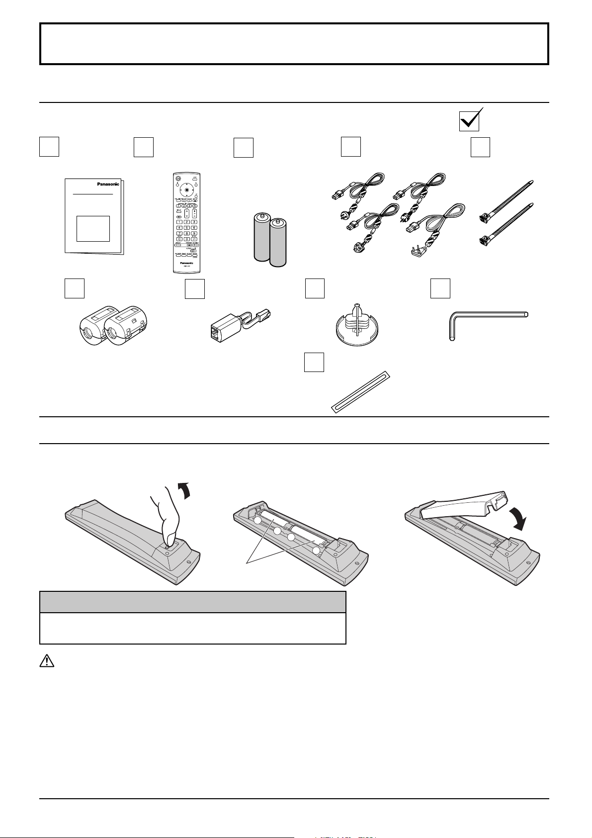
Accessories .............................................................. 9
Accessories Supply ................................................. 9
Remote Control Batteries ........................................ 9
Connections............................................................ 10
AUDIO OUT Terminals connection........................ 10
PC Input Terminals connection...............................11
SERIAL Terminals connection ............................... 12
HDMI connection................................................... 13
COMPONENT / RGB connection.......................... 13
Power On / Off......................................................... 14
Selecting the input signal...................................... 16
Basic Controls ........................................................ 17
ASPECT Controls ................................................... 19
MULTI PIP ................................................................ 20
Digital Zoom............................................................ 22
On-Screen Menu Displays ..................................... 23
Adjusting Pos. /Size ............................................... 25
Picture Adjustments............................................... 28
Advanced settings ................................................. 29
Picture Profiles ....................................................... 30
Saving profiles....................................................... 31
Loading profiles ..................................................... 32
Editing profiles....................................................... 32
Locking profiles ..................................................... 33
Sound Adjustment.................................................. 35
SDI Sound Output ................................................. 35
PRESENT TIME Setup / Set up TIMER.................. 36
PRESENT TIME Setup.......................................... 36
Set up TIMER ........................................................ 36
Screensaver (For preventing image retention).... 37
Setup of Screensaver Time ................................... 38
Reduces screen image retention .......................... 39
Extended life settings ............................................ 39
Reduces power consumption ............................... 42
Customizing the Input labels................................. 43
Selecting the On-Screen Menu Language............ 43
Display orientation ................................................. 44
Setup for MULTI DISPLAY...................................... 45
How to Setup MULTI DISPLAY ............................. 45
ID Remote Control Function.................................. 46
MULTI PIP Setup ..................................................... 47
Set up for Portrait................................................... 48
How to setup Portrait............................................. 48
Setup for Input Signals .......................................... 50
Component / RGB-in select................................... 50
YUV / RGB-in select.............................................. 50
Signal menu .......................................................... 51
3D Y/C Filter .......................................................... 51
Colour system / Panasonic Auto ........................... 52
Cinema reality ....................................................... 52
XGA Mode ............................................................. 52
Refresh Rate ......................................................... 53
Noise reduction ..................................................... 53
Sync ...................................................................... 54
SDI Through .......................................................... 54
Input signal display................................................ 54
Network Setup ........................................................ 55
Options Adjustments ............................................. 56
Weekly Command Timer ....................................... 59
Shipping condition................................................. 60
Using Network Function ........................................ 61
Example of Network Connection ........................... 61
Command Control ................................................. 61
PJLink™ Protocol.................................................. 62
Troubleshooting ..................................................... 63
List of Aspect Modes ............................................. 64
Applicable Input Signals........................................ 65
Command list of Weekly Command Timer........... 67
Specifications ......................................................... 68
Customer Service ...................................................69

6
Safety Precautions
CAUTION
This Plasma Display is for use only with the following optional accessories. Use with any other type of optional
accessories may cause instability which could result in the possibility of injury.
(All of the following accessories are manufactured by Panasonic Corporation.)
Always be sure to ask a qualified technician to carry out set-up.
Small parts can present choking hazard if accidentally swallowed. Keep small parts away from young children. Discard
unneeded small parts and other objects, including packaging materials and plastic bags/sheets to prevent them from
being played with by young children, creating the potential risk of suffocation.
• Pedestal ......................................................................... TY-ST103PF9
• Wall-hanging bracket (vertical)....................................... TY-WK103PV9
• Ceiling-hanging bracket ................................................. TY-CE103PS10
• BNC Component Video Terminal Board......................... TY-42TM6A
• BNC Composite Video Terminal Board .......................... TY-42TM6B
• BNC Dual Video Terminal Board .................................... TY-FB9BD
• RCA Component Video Terminal Board......................... TY-42TM6Z
• RCA Composite Video Terminal Board .......................... TY-42TM6V
• RGB Active Through Terminal Board ............................. TY-42TM6G
• PC Input Terminal Board ................................................ TY-42TM6P
• Composite / Component Video Terminal Board ............. TY-42TM6Y
• BNC SDI Terminal Board ............................................... TY-FB7SD
• HD-SDI Terminal Board.................................................. TY-FB9HD
• HD-SDI Terminal Board with audio ................................ TY-FB10HD
• Dual Link HD-SDI Terminal Board.................................. TY-FB11DHD
• HDMI Terminal Board..................................................... TY-FB8HM
• Dual HDMI Terminal Board ............................................ TY-FB10HMD
• Scart Terminal Board...................................................... TY-FB8SC
• Ir Through Terminal Board.............................................. TY-FB9RT
• DMB-T PAL Tuner Board................................................ TY-FB12DTH∗1
• DVB-T Tuner Board........................................................ TY-FB11DTA∗2
• Wireless Presentation Board.......................................... TY-FB10WPE∗3
• DVI-D Terminal Board .................................................... TY-FB11DD
• AV Terminal Box ............................................................. TY-TB10AV
∗1Only for Hong Kong.
∗2Only for Australia.
∗3Except for CIS region (Russia, Ukraine, Belarus, Kazakhstan, Uzbekistan)
When using the Plasma Display
Do not bring your hands, face or objects close to the ventilation holes of the Plasma Display.
• Top of the Plasma Display is usually very hot due to the high temperature of exhaust air being released through
the ventilation holes. Burns or personal injuries can happen if any body parts are brought too close. Placing any
object near the top of the display could also result in heat damages to the object as well as to the Display if its
ventilation holes are blocked.
Be sure to disconnect all cables before moving the Plasma Display.
• Moving the Display with its cables attached might damage the cables which, in turn, can cause fire or electric
shock.
Disconnect the power plug from the wall outlet as a safety precaution before carrying out any cleaning.
• Electric shocks can result if this is not done.
Clean the power cable regularly to prevent it from becoming dusty.
• Built-up dust on the power cord plug can increase humidity which might damage the insulation and cause fire.
Unplug the cord from the wall outlet and clean it with a dry cloth.

7
Safety Precautions
Do not burn or breakup batteries.
• Batteries must not be exposed to excessive heat such as sunshine, fire or the like.
This Plasma Display radiates infrared rays, therefore it may affect other infrared communication equipment.
Install your infrared sensor in a place away from direct or reflected light from your Plasma Display.
Note:
Do not allow a still picture to be displayed for an extended period, as this can cause a permanent image retention to
remain on the Plasma Display.
Examples of still pictures include logos, video games, computer images, teletext and images displayed in 4:3 mode.
WARNING
Setup
Do not place the Plasma Display on sloped or unstable surfaces.
• The Plasma Display may fall off or tip over.
Do not place any objects on top of the Plasma Display.
• If water spills onto the Plasma Display or foreign objects get inside it, a short-circuit may occur which could result
in fire or electric shock. If any foreign objects get inside the Plasma Display, please consult an Authorized Service
Center.
Do not cover the ventilation holes.
• Doing so may cause the Plasma Display to overheat, which can cause fire or damage to the Plasma Display.
Transport only in upright position!
• Transporting the unit with its display panel facing upright or downward may cause damage to the internal
circuitry.
If using the pedestal (optional accessory), leave a space of 12.0” / 30 cm or more at the top, left and right,
and 8.0” / 20 cm or more at the rear, and also keep the space between the bottom of the display and the floor
surface. If using some other setting-up method, follow the manual of it. (If there is no specific indication of
installation dimension in the installation manual, leave a space of 12.0” / 30 cm or more at the top, bottom,
left and right, and 8.0” / 20 cm or more at the rear.)
An apparatus with CLASS I construction shall be connected to a mains socket outlet with a protective earthing
connection.
AC Power Supply Cord
The Plasma Display is designed to operate on 200-240 V AC, 50/60 Hz.
Ensure that the mains plug is easily accessible.
Do not use any power supply cord other than that provided with this unit.
• Doing so may cause fire or electric shocks.
Securely insert the power cord plug as far as it will go.
• If the plug is not fully inserted, heat may be generated which could cause fire. If the plug is damaged or the wall
socket plate is loose, they should not be used.
Do not handle the power cord plug with wet hands.
• Doing so may cause electric shocks.
Do not do anything that might damage the power cable. When disconnecting the power cable, hold the plug,
not the cable.
• Do not make any modifications, place heavy objects on, place near hot objects, heat, bend, twist or forcefully pull
the power cable. Doing so may cause damage to the power cable which can cause fire or electric shock. If damage
to the cable is suspected, have it repaired at an Authorized Service Center.
If the Plasma Display will not be used for a long period of time, unplug the power cord from the wall outlet.

8
Safety Precautions
Cleaning and maintenance
The front of the display panel has been specially treated. Wipe the panel surface gently using only a cleaning
cloth or a soft, lint-free cloth.
• If the surface is particularly dirty, wipe with a soft, lint-free cloth which has been soaked in pure water or water in
which neutral detergent has been diluted 100 times, and then wipe it evenly with a dry cloth of the same type until
the surface is dry.
• Do not scratch or hit the surface of the panel with fingernails or other hard objects, otherwise the surface may
become damaged. Furthermore, avoid contact with volatile substances such as insect sprays, solvents and thinner,
otherwise the quality of the surface may be adversely affected.
If the cabinet becomes dirty, wipe it with a soft, dry cloth.
• If the cabinet is particularly dirty, soak the cloth in water to which a small amount of neutral detergent has been
added and then wring the cloth dry. Use this cloth to wipe the cabinet, and then wipe it dry with a dry cloth.
• Do not allow any detergent to come into direct contact with the surface of the Plasma Display. If water droplets get
inside the unit, operating problems may result.
• Avoid contact with volatile substances such as insect sprays, solvents and thinner, otherwise the quality of the
cabinet surface may be adversely affected or the coating may peel off. Furthermore, do not leave it for long periods
in contact with articles made from rubber or PVC.
If problems occur during use
If a problem occurs (such as no picture or no sound), or if smoke or an abnormal odor is detected from the
Plasma Display, unplug the power cord immediately.
• Continuous use of the Display under these conditions might cause fire or permanent damage to the unit. Have
the Display evaluated at an Authorized Service Center. Services to the Display by any unauthorized personnel are
strongly discouraged due to its high voltage dangerous nature.
If water or foreign objects get inside the Plasma Display, if the Plasma Display is dropped, or if the cabinet
becomes damaged, disconnect the power cord plug immediately.
• A short may occur, which could cause fire. Contact an Authorized Service Center for any repairs that need to be
made.

9
+
+
-
-
Accessories Supply
Accessories
Eyebolt cap × 3
Blind sheet × 1
Allen wrench
Ferrite core × 2 Noise cut filter
Batteries for
the Remote
Control
Transmitter
(R6 Size × 2)
Power supply cord Fixing band
× 2
Remote Control
Transmitter
EUR7636070R
Operating
Instruction
book
Check that you have the accessories and items shown
Remote Control Batteries
Helpful Hint:
For frequent remote control users, replace old batteries with Alkaline
batteries for longer life.
Precaution on battery use
Incorrect installation can cause battery leakage and corrosion that will damage the remote control transmitter.
Disposal of batteries should be in an environment-friendly manner.
Observe the following precaution:
1. Batteries shall always be replaced as a pair. Always use new batteries when replacing the old set.
2. Do not combine a used battery with a new one.
3. Do not mix battery types (example: “Zinc Carbon” with “Alkaline”).
4. Do not attempt to charge, short-circuit, disassemble, heat or burn used batteries.
5.
Battery replacement is necessary when remote control acts sporadically or stops operating the Plasma Display set.
6. Do not burn or breakup batteries.
Batteries must not be exposed to excessive heat such as sunshine, fire or the like.
Requires two R6 batteries.
1. Pull and hold the hook, then open
the battery cover.
2. Insert batteries - note correct
polarity (+ and -).
3. Replace the cover.
“R6” size
Use the Ferrite cores and Noise cut filter to
comply with the EMC standard. (see page 61)

SERIALPC IN
AUDIO
SLOT1 SLOT3
PR/CR/R PB/CB/B
Y/G
COMPONENT/RGB INLAN
SLOT2
AUDIO
1 2
AUDIO OUT
R L
AUDIO OUT
R L
10
Connections
Stereophonic sound code
line-in
audio equipment
AUDIO OUT Terminals connection
Pass the attached cable
fixing band through the clip
as shown in the figure.
To secure cables connected to Terminals, wrap the cable fixing band around them
then pass the pointed end through the locking block, as shown in the figure.
While ensuring there is sufficient slack in cables to minimize stress (especially
in the power cord), firmly bind all cables with the supplied fixing band.
To tighten: To loosen:
Pull
Pull
Push the catch
– AC cord fixing
Note: Terminal board is installed in SLOT 2 and SLOT 3 at factory shipment.
– Cable fixing band
Secure any excess cables with band as required.
Note:
Two fixing bands are supplied with this unit. In case of securing cables at four positions, please purchase it separately.
Push
until
the hook
clicks.
2. Pull
off.
Close
Open
1 Plug the AC cord into the display unit.
Plug the AC cord until it clicks.
2 Fix the AC cord with the clamper.
Note:
Make sure that the AC cord is locked on both the left and right sides.
1. Keep the
knob
pressed.
Unplug the AC cord
Unplug the AC
cord pressing
the two knobs.
Note:
When disconnecting the AC cord,
be absolutely sure to disconnect
the AC cord plug at the socket
outlet first.
From SERIAL
Terminal on
Computer
(see page 12)
From input
on audio
amplifier
(see page 10)
From EXTERNAL
monitor terminal
on Computer
(see page 11)
Dual HDMI Terminals
(equivalent of Dual
HDMI Terminal Board
(TY-FB10HMD))
(see page 13)
Optional
Terminal
Board Insert
Slot (covered)
COMPONENT/
RGB IN
Terminals
(see page 13)
LAN Terminal
(see page 61)
AC cord connection (see page 14)

AUDIO
PC IN
11
Connections
1
678
3
9
45
10
15 14 13 12 11
2
Notes:
• With regard to the typical PC input signals that are described in the applicable input signals list (see page 65), adjustment
values such as for the standard picture positions and sizes have already been stored in this unit. You can add up to eight
PC input signal types that are not included in the list.
• Computer signals which can be input are those with a horizontal scanning frequency of 15 to 110 kHz and vertical scanning
frequency of 48 to 120 Hz. (However, the image will not be displayed properly if the signals exceed 1,200 lines.)
• The display resolution is a maximum of 1,440 × 1,080 dots when the aspect mode is set to “4:3”, and 1,920 × 1,080
dots when the aspect mode is set to “16:9”. If the display resolution exceeds these maximums, it may not be possible
to show fine detail with sufficient clarity.
• The PC input terminals are DDC2B-compatible. If the computer being connected is not DDC2B-compatible, you will
need to make setting changes to the computer at the time of connection.
• Some PC models cannot be connected to the set.
• There is no need to use an adapter for computers with DOS/V compatible Mini D-sub 15P terminal.
• The computer shown in the illustration is for example purposes only.
• Additional equipment and cables shown are not supplied with this set.
• Do not set the horizontal and vertical scanning frequencies for PC signals which are above or below the specified
frequency range.
• Component Input is possible with the pin 1, 2, 3 of the Mini D-sub 15P Connector.
• Change the “Component/RGB-in select” setting in the “Setup” menu to “Component”
(when Component signal connection) or “RGB” (when RGB signal connection). (see page 50)
Signal Names for Mini D-sub 15P Connector
Pin Layout for PC Input
Terminal
PC Input Terminals connection
COMPUTER
Conversion adapter
(if necessary) Mini D-sub 15p
RGB
PC cable
Stereo plug
Audio
Connect a cable which matches
the audio output terminal on the computer.
Pin No. Signal Name Pin No. Signal Name Pin No. Signal Name
1R (PR/CR)6GND (Ground)
11
NC (not connected)
2G (Y) 7GND (Ground)
12
SDA
3B (PB/CB)8GND (Ground)
13
HD/SYNC
4NC (not connected) 9+5 V DC
14
VD
5GND (Ground)
10
GND (Ground)
15
SCL
(Male)
(Female)

SERIAL
6 7 8 9
1 3 4 52
12
SERIAL Terminals connection
Notes:
• Use the RS-232C straight cable to connect the computer to the Plasma Display.
• The computer shown is for example purposes only.
• Additional equipment and cables shown are not supplied with this set.
The SERIAL terminal conforms to the RS-232C interface
specification, so that the Plasma Display can be controlled
by a computer which is connected to this terminal.
The computer will require software which allows the
sending and receiving of control data which satisfies
the conditions given below. Use a computer application
such as programming language software. Refer to the
documentation for the computer application for details.
The SERIAL terminal is used when the Plasma Display is controlled by a computer.
Pin layout for SERIAL Terminal
Basic format for control data
The transmission of control data from the computer
starts with a STX signal, followed by the command, the
parameters, and lastly an ETX signal in that order. If there
are no parameters, then the parameter signal does not
need to be sent.
STX C1 C2 C3 P1 P2 P3 P4: P5 ETX
Start
(02h)
3-character
command (3 bytes)
Colon Parameter(s)
(1 - 5 bytes)
End
(03h)
Notes:
• If multiple commands are transmitted, be sure to wait for
the response for the first command to come from this unit
before sending the next command.
• If an incorrect command is sent by mistake, this unit will
send an “ER401” command back to the computer.
• SL1A, SL1B, SL2A and SL2B of Command IMS are
available only when a dual input terminal board is
attached.
COMPUTER
RS-232C Straight cable
D-sub 9p
Communication parameters
Signal level RS-232C compliant
Synchronization method Asynchronous
Baud rate 9600 bps
Parity None
Character length 8 bits
Stop bit 1 bit
Flow control -
Signal names for D-sub 9P connector
Pin No. Details
2R X D
3T X D
5GND
4•6Non use
7
8(Shorted in this set)
1•9NC
These signal names are those of computer specifications.
Connections
Command
Command Parameter Control details
PON None Power ON
POF None Power OFF
AVL ** Volume 00 - 63
AMT 0 Audio MUTE OFF
1 Audio MUTE ON
IMS None
SL1
SL2
SL3
PC1
SL1A
SL1B
SL2A
SL2B
Input select (toggle)
Slot1 input
Slot2 input
Slot3 input
PC input
Slot1 input (INPUT1A)
Slot1 input (INPUT1B)
Slot2 input (INPUT2A)
Slot2 input (INPUT2B)
DAM None
ZOOM
FULL
JUST
NORM
SELF
ZOM2
ZOM3
SJST
SNOM
SFUL
14:9
Screen mode select (toggle)
Zoom1
(For Video/SD/PC signal)
16:9
Just (For Video/SD signal)
4:3 (For Video/SD/PC signal)
Panasonic Auto (For Video singal)
Zoom2 (For HD signal)
Zoom3 (For HD signal)
Just (For HD signal)
4:3 (For HD signal)
4:3 Full (For HD signal)
14:9
With the power off, this display responds to PON command
only.
(Male)
(Female)
Note: To use serial control for this unit, make sure to set the “Control I/F Select” in the “Network Setup” menu to
“RS-232C”. (see page 55)

SLOT3
P
R
/C
R
/R P
B
/C
B
/B
Y/G
COMPONENT/RGB INLAN
AUDIO
AUDIO
OUT
Y, P
B, PR,
OUT
P
R
PB
Y
L
R
COMPONENT VIDEO OUT
13
Connections
HDMI connection
COMPONENT / RGB connection
Notes:
• Change the “Component/RGB-in select” setting in the “Setup” menu to “Component”
(when Component signal connection) or “RGB” (when RGB signal connection). (see page 50)
• Additional equipment, cables and adapter plugs shown are not supplied with this set.
• Sync on G signal is needed. (see page 54)
RCA-BNC
adapter plug
Mini-plug (M3)
Computer RGB Camcorder
or
DVD
Example of input signal source
Digital TV-SET-TOP-BOX
(DTV-STB)
PC I
N
SLOT1 SLOT2
HDMI
AV OUT
HDMI
AV OUT
P
R
/C
R
/R P
B
/C
B
/B
Y/G
COMPONENT/RGB INLAN
AUDIO
This unit has terminal boards equivalent to Dual HDMI Terminal Board (TY-FB10HMD) as standard equipment.
HDMI cables
DVD player DVD player
[Pin assignments and signal names]
19
3 1
4 2
18
Note:
Additional equipment and HDMI cables shown are not supplied with this set.
Pin No.
Signal
Pin No.
Signal
1 T.M.D.S Data2+
11
T.M.D.S Clock
Shield
2 T.M.D.S Data2
Shield
12
T.M.D.S Clock-
3 T.M.D.S Data2-
13
CEC
4 T.M.D.S Data1+
14
Reserved
(N.C. on
device)
5 T.M.D.S Data1
Shield
6 T.M.D.S Data1-
15
SCL
7 T.M.D.S Data0+
16
SDA
8 T.M.D.S Data0
Shield
17
DDC/CEC
Ground
9 T.M.D.S Data0-
18
+5V Power
10
T.M.D.S Clock+
19
Hot Plug Detect

Right side surface
Main Power
On / Off Switch
14
Power On / Off
Connecting the AC cord plug to the Plasma Display.
Fix the AC cord plug securely to the Plasma
Display with the clamper. (see page 10)
Press the button on the remote control to turn the Plasma Display off.
Power Indicator: Red (standby)
Press the button on the remote control to turn the Plasma Display on.
Power Indicator: Green
Turn the power to the Plasma Display off by pressing the switch on the
unit, when the Plasma Display is on or in standby mode.
Note:
During operation of the power management function, the power indicator turns
orange in the power off state.
Connecting the plug to the Wall Outlet
Notes:
• Main plug types vary between countries. The power
plug shown at right may, therefore, not be the type
fitted to your set.
• When disconnecting the AC cord, be absolutely
sure to disconnect the AC cord plug at the socket
outlet first.
Press the Power switch on the Plasma Display to
turn the set on: Power-On.
Power Indicator: Green
Power IndicatorRemote Control
Sensor

PRESENT TIME Setup
PRESENT TIME MON 99:99
Set
PRESENT TIME 99:99
DAY MON
PRESENT TIME Setup
PRESENT TIME MON 99:99
Set
PRESENT TIME 10:00
DAY TUE
Landscape
Portrait
Display orientation
PC
16:9
NANODRIFT
Italiano
Español
ENGLISH (US)
Русский
English (UK)
Deutsch
Français
OSD Language
SetSelect
15
From the second time on, the below screen is displayed for a while (setting condition is an example).
Power On / Off
When first switching on the unit
Following screen will be displayed when the unit is turned on for the first time.
Select the items with the remote control. Unit buttons are invalid.
OSD Language
PRESENT TIME Setup
Display orientation
1 Select the language.
2 Set.
1 Select “DAY” or “PRESENT TIME”.
2 Setup “DAY” or “PRESENT TIME”.
1 For vertical installation, select “Portrait”.
2 Set.
Notes:
• Once the items are set, the screens won’t be displayed when switching on the unit next time.
• After the setting, the items can be changed in the following menus.
OSD Language (see page 43)
PRESENT TIME Setup (see page 36)
Display orientation (see page 44)
1 Select “Set”.
2 Set.

INPUT
MENU
VOL
ENTER/
+ /
-
/
16
Selecting the input signal
Notes:
• Selecting is also possible by pressing the INPUT button on the unit.
• Input terminal will not be selected if the terminal board is not installed
into the SLOT.
• Select to match the signals from the source connected to the
component/RGB input terminals. (see page 50)
• In 2 screen display, the same input mode cannot be selected for the
main picture and sub picture.
• Image retention (image lag) may occur on the plasma display panel
when a still picture is kept on the panel for an extended period. The
function that darkens the screen slightly is activated to prevent image
retention (see page 63), but this function is not the perfect solution to
image retention.
Select the input signals to be connected by installing the optional Terminal Boards.
Press to select the input signal to be played back from the
equipment which has been connected to the Plasma Display.
Input signals will change as follows:
INPUT1
INPUT2A
PCINPUT3
INPUT2B
SLOT2 is for dual input so that you can select INPUT2A or
INPUT2B for INPUT2.
INPUT2A : HDMI signal terminal in SLOT2
INPUT2B : HDMI signal terminal in SLOT2
Press the INPUT “1”, “2”, “3” or “PC” input mode selection button
to select the INPUT mode.
Press to switch the input mode between INPUT2A and
INPUT2B.

17
Basic Controls
Main Unit
INPUT
MENU
VOL
ENTER/
+ /
-
/
Right side
surface
Remote control sensor
Main Power On / Off Switch
Power Indicator
The Power Indicator will light.
• Power-OFF .... Indicator not illuminated (The
unit will still consume some
power as long as the power
cord is still inserted into the wall
outlet.)
• Standby ........ Red
Orange (When “Slot power” is
set to “On”. See page 58)
Orange (Depending on the
type of the function board
installed, when the power is
supplied to the slot)
Orange (When “Control I/F
Select” is set to “LAN”. See
page 55)
• Power-ON...... Green
• DPMS (Power management)
.........................Orange (With PC input signal.
See page 42)
Volume Adjustment
Volume Up “+” Down “–”
When the menu screen is displayed:
“+”: press to move the cursor up
“–”:
press to move the cursor down
(see page 23)
Enter / Aspect button
(see page 19, 23)
MENU Screen ON / OFF
Each time the MENU button is pressed, the
menu screen will switch. (see page 23)
Normal Viewing Picture
Sound Pos. /Size Setup
INPUT button
(INPUT signal selection)
(see page 16)

18
Basic Controls
Standby (ON / OFF) button
The Plasma Display must first be plugged into the wall outlet
and turned on at the power switch (see page 14).
Press ON to turn the Plasma Display On, from Standby mode.
Press OFF to turn the Plasma Display Off to Standby mode.
SET UP button (see page 23)
SOUND button (see page 34)
DIRECT INPUT buttons
Press the INPUT “1”, “2”, “3” or “PC”
input mode selection button to select
the INPUT mode. (see page 16)
This button is used to switch directly
to INPUT mode.
Volume Adjustment
Press the Volume Up “+” or Down
“–” button to increase or decrease
the sound volume level.
Channel Adjustment
This button cannot be used for this
model.
OFF TIMER button
The Plasma Display can be preset
to switch to stand-by after a fixed
period. The setting changes to 30
minutes, 60 minutes, 90 minutes
and 0 minutes (off timer cancelled)
each time the button is pressed.
30 60
0
90
When three minutes remain, “Off
timer 3” will flash.
The off timer is cancelled if a power
interruption occurs.
Remote ID lock (see page 46)
Digital Zoom (see page 22)
MULTI Window buttons
(see page 20)
Status button
Press the “Status” button to display
the current system status.
1
Input label
2
Aspect mode (see page 19)
NANODRIFT Saver operating
(see page 40)
3
Off timer
The off timer indicator is displayed
only when the off timer has been set.
4
Clock display (see page 58)
R button (see page 23)
Press the R button to return to previous menu screen.
POSITION buttons
ACTION button
Press to make selections.
POS. /SIZE button
(see page 25)
PICTURE button
(see page 28)
INPUT button
Press to select INPUT1, INPUT2,
INPUT3 and PC input SLOTS
sequentially. (see page 16)
When a dual input terminal
board is attached, A or B is
displayed depending on the
selected input signal.
(Ex. INPUT1A, INPUT1B)
Sound mute On / Off
Press this button to mute the sound.
Press again to reactivate sound.
Sound is also reactivated when
power is turned off or volume
level is changed.
Numeric buttons
(see page 46)
ASPECT button
Press to adjust the aspect.
(see page 19)
N button
(see page 27, 28, 29, 35)
Remote Control Transmitter
SURROUND button
The surround setting switches on and off each time the
SURROUND button is pressed.
The benefits of surround sound are enormous. You can
be completely enveloped in sound; just as if you were
at a concert hall or cinema.
On
Surround
On Off
Off timer 90
1
2
3
410:00
PC
4:3
NANODRIFT

Zoom1 Zoom2
Just
Panasonic Auto
Zoom3
16:9
4:3
14:9
[from the unit]
VOL
ENTER/
+/
-
/
Right side surface
19
ASPECT Controls
The Plasma Display will allow you to enjoy viewing the picture at its maximum size, including wide screen cinema
format picture.
For HD signal input [1125 (1080) / 60i • 50i • 60p • 50p • 24p • 25p • 30p • 24sF, 1250 (1080) / 50i,
750 (720) / 60p • 50p]:
4:3 Full Zoom1
14:9Just
Zoom2
Zoom3
4:3
16:9
[During MULTI PIP Operations]
•
Picture and Picture, Picture in Picture
: 4:3 16:9
• Others : Aspect switching is not possible.
Press repeatedly to move through the aspect options:
For details about the aspect mode, please see “List of Aspect Modes” (page 64).
Note:
When selecting an input slot that attaches BNC Dual Video Terminal
Board (TY-FB9BD), Panasonic Auto cannot be selected.
Note:
Be aware that if you put the display in a public place for commercial purposes or a public showing
and then use the aspect mode select function to shrink or expand the picture, you may be violating
the copyright under copyright law. It is prohibited to show or alter the copyrighted materials of other
people for commercial purposes without the prior permission of the copyright holder.
The aspect mode changes each time the ENTER button is pressed.
4:3 Zoom 16:9
For PC signal input: For SD signal input (525 (480) / 60i • 60p, 625 (575) / 50i • 50p):
4:3 Zoom1 16:9Zoom2 Zoom3 14:9 Just
Notes:
• Panasonic Auto can be selected only during
Video signal input.
• The aspect mode is memorized separately for
each input terminal.
• Do not allow the picture to be displayed in 4:3
mode for an extended period, as this can cause
a permanent image retention to remain on the
Plasma Display Panel.
Panasonic Auto
The display will automatically become enlarged (depending on the picture source), allowing you to view the picture at its maximum size.
Panasonic Auto
4 16
3 9
Notes:
• Panasonic Auto mode is designed to automatically adjust the
aspect ratio to handle a mix of 16:9 and 4:3 program material.
Certain 4:3 program material, such as stock market data screens,
may occasionally cause the image size to change unexpectedly.
When viewing such programs, it is recommended that the
ASPECT be set to 4:3.
• If adjusting the Picture V-Pos/V-Size in Panasonic Auto with
16:9 mode, the adjustment is not memorized. When exiting the
mode, the screen will return to a former adjustment.
For letter box image Image is expanded
4
3
Changes in accordance with
the Panasonic Auto mode
setting (see page 52).
For a 4:3 image
4:3 Zoom1 16:9 JustZoom2 Zoom3 Panasonic Auto 14:9
All Aspect mode
Set “All Aspect” to “On” in Options menu to enable the extended aspect mode (page 58). When All Aspect mode, the aspect
mode of pictures is switched as follows. For details about the aspect mode, please see “List of Aspect Modes” (page 64)
For VIDEO (S VIDEO) signal input:
Note: When selecting an input slot that attaches BNC Dual Video Terminal Board (TY-FB9BD), Panasonic Auto cannot
be selected.
For SD signal input (525 (480) / 60i
•
60p, 625 (575) / 50i
•
50p):
4:3 Zoom 16:9
For PC signal input:
For HD signal input [1125 (1080) / 60i • 50i • 60p • 50p • 24p • 25p • 30p • 24sF, 1250 (1080) / 50i, 750 (720) / 60p • 50p]:
4:3 Zoom1 16:9 JustZoom2 Zoom3 14:9
4:3 Full Zoom1 16:9 Just1Zoom2 Zoom3 14:9 Just2 4:3 (1) 4:3 (2)
For VIDEO (S VIDEO) signal input:

20
MULTI PIP
You can display two pictures, such as a video image and computer image, in a two-screen display. (Use the remote
control for this operation. It cannot be performed with the buttons on the main unit.)
MULTI PIP Setup
Set the functions and mode for two-screen display in “MULTI PIP Setup” in the Setup menu.
(see page 47)
Selecting the Display Mode
Each time this button is pressed, the screen changes.
Note:
The screen changes in the same way when “Display Mode” in “MULTI PIP Setup” is changed. (see page 47)
During PIP: During Advanced PIP:
One screen Advanced PIP
Main screen
Sub screen1–
8
2
7
3
6
4
5
One screen Two screens (P and P)
Sub screen
input mode
Main screen
input mode
Two screens (P out P)Two screens (P in P)
Main screen Sub screen
INPUT1
PC
PC
INPUT1
INPUT1
PC
Note:
and button operations are not available during
advanced PIP.
During Blend PIP (Composite Screen Function):
A composite picture is displayed with the sub screen positioned over the main screen. For example, text data such as
a computer image can be displayed as a caption over a movie or still image.
One screen Full P in P
Table of contents