manuals.online logo
Brands
  1. Home
  2. •
  3. Brands
  4. •
  5. Panasonic
  6. •
  7. Plasma TV
  8. •
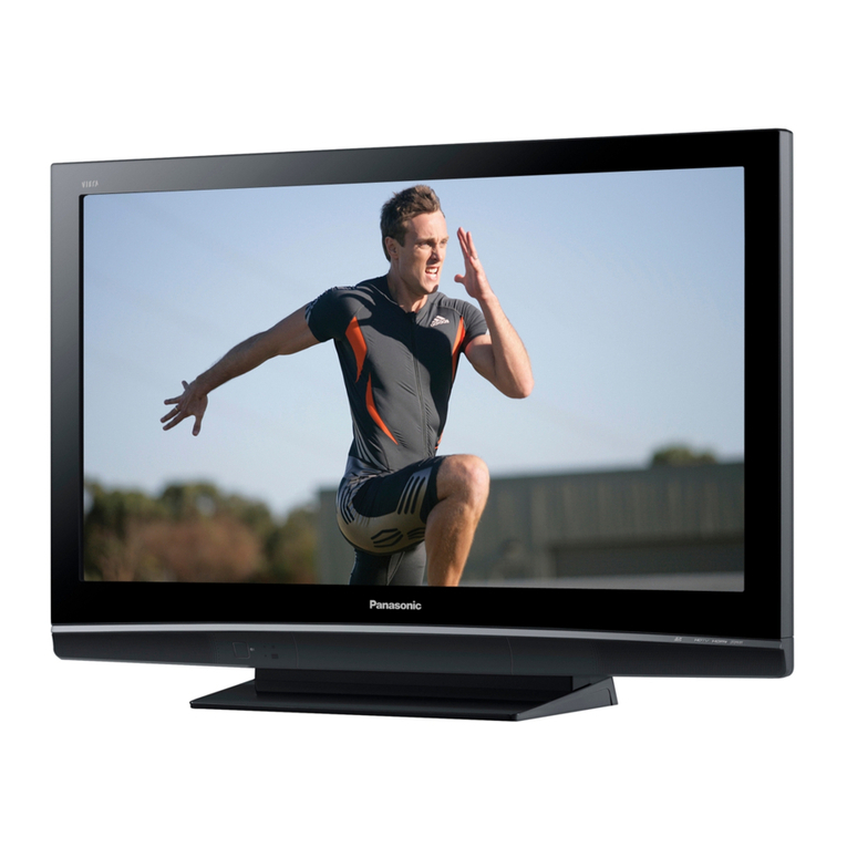
  9. Panasonic TH-42PV600AZ User manual

Panasonic TH-42PV600AZ User manual

ORDERNO.ITD0604019CE
PlasmaTelevision
TH-42PV600AZ / TH-42PV600H / TH-42PV600M/ TH-
42PV600MT
GP9DEChassis
SPECIFICATIONS
Specifications
Power
Source AC220-240 V, 50 / 60 Hz
Power
Consumption
Averageuse 341 W
Standbycondition 0.3W
Plasma
Displaypanel
Drivemethod ACtype
AspectRatio 16:9
ContrastRatio Max 10000:1
Visiblescreen size/ (No.
ofpixels) 106 cmV
920 mm (W)×518 mm (H)×1,056 mm (diagonal)
786,432 (1,024 (W)×768 (H)) [3,072 ×768 dots]
Sound
Speaker Woofer( 80 mm)×2pcs, Tweeter(23 mm ×100 mm)×2pcs
Audio Output 31 W (15.5W +15.5W ), 10%THD
Headphones M3(3.5mm)stereo mini Jack ×1
PC
signals VGA, SVGA, XGA
SXGA (compressed)
Horizontal scanning frequency31 -69 kHz
Vertical scanning frequency59 -86 Hz
1
Receiving
Systems / / Band
name
(PV600AZ)
Receiving
Channels
PV600AZ)
VHF 0to 12 PAL B
UHF 21 to 69 PAL G
S’1to S’3 HYPERTUNER
S1to S41
Receiving
Systems / / Band
name
(PV600H/M/MT)
Receiving
Channels/
Regular
TV) (PV600H/M/MT) VHF BAND UHF BAND CATV
2-12(PAL/SECAMB,K1) 21-69(PAL,G,H,I/SECAMG,K,K1) S1-S20(OSCAR)
0-12(PAL BAUST.) 28-69(PAL BAUST.) 1-125(USACATV)
1-9(PAL BN.Z.) 13-57(PAL D,K) C13-C49(JAPAN)
1-12(PAL/SECAMD) 13-62(NTSCMJapan) S21-S41(HYPER)
1-12(NTSCMJapan) 14-69(NTSCMUSA) Z1-Z37(CHINA)
2-13(NTSCMUSA) 5A,9A(AUST.)
Aerial
-Rear VHF / UHF
Operating
Conditions Temperature:0°C-40 °C
Humidity:20 %-80 %RH(non-condensing)
Connection
Terminals
AV1
Input AUDIOL-R RCAPINType×2 0.5V[rms]
VIDEO RCAPINType×1 1.0V[p-p](75 )
SVIDEO Mini DIN4-pin Y:1.0V[p-p](75 )C:0.286 V[p-p](75 )
AV2
Input AUDIOL-R RCAPINType×2 0.5V[rms]
VIDEO RCAPINType×1 1.0V[p-p](75 )
COMPONENT Y
PB/CB, PR/CR1.0V[p-p](including synchronization)
±0.35 V[p-p]
AV3
Input AUDIOL-R RCAPINType×2 0.5V[rms]
VIDEO RCAPINType×1 1.0V[p-p](75 )
COMPONENT Y
PB/CB, PR/CR1.0V[p-p](including synchronization)
±0.35 V[p-p]
AV4
Input AUDIOL-R RCAPINType×2 0.5V[rms]
VIDEO RCAPINType×1 1.0V[p-p](75 )
SVIDEO Mini DIN4-pin Y:1.0V[p-p](75 )C:0.286 V[p-p](75 )
Others HDMI1/2Input TYPEAConnectors
PCInput HIGH-DENSITYD-SUB 15PIN R,G,B/0.7V[p-p](75 )
HD,VD/TTL Level 2.0-5.0V[p-p](high impedance)
Audio Input RCAPINType×2 0.5V[rms]
Card slot SDCARDslot×1
MonitorAUDIOL-R RCAPINType×2 0.5V[rms](high impedance)
2
Output VIDEO RCAPINType×1 1.0V[p-p](75 )
Dimensions
(W ×H×D)
1,077 mm ×689 mm ×138 mm (panel part: 95)
Weight
32.5kg Net
Notes
:
-Design and Specificationsaresubjectto changewithout notice. Weight and Dimensionsshownareapproximate.
1. Applicablesignals
2. SafetyPrecautions
2.1. General Guidelines
1. Whenservicing, observetheoriginal leaddress. Ifashortcircuit
isfound, replace all parts whichhavebeenoverheatedor
damagedbytheshortcircuit.
2. Afterservicing, see toitthat all theprotectivedevices suchas
3
insulation barriers, insulation papersshieldsareproperlyinstalled.
3. Afterservicing, make thefollowing leakagecurrentchecks to
preventthecustomerfrombeing exposedtoshock hazards.
2.2. Touch-CurrentCheck
1. Plug theACcorddirectlyintotheACoutlet. Donotuse an
isolation transformerforthischeck.
2. Connect ameasuring networkfortouchcurrents betweeneach
exposedmetallicparton theset and agood earthground suchas
awaterpipe, as shownin Figure 1.
3. Use LeakageCurrentTester(Simpson 228 orequivalent) to
measurethepotential across themeasuring network.
4. Check eachexposedmetallicpart, and measurethevoltageat
eachpoint.
5. ReservetheACplug intheACoutlet and repeat eachoftheabove
measure.
6. Thepotential at anypoint(TOUGHCURRENT)expressedas
voltageU1and U2, does notexceedthefollowing values:
Fora. c.:U1=35 V(peak) and U2=0.35 V(peak);
Ford. c.:U1=1.0V,
Note:
ThelimitvalueofU2=0.35 V (peak)for a. c. and U1=1.0V for d. c. correspond tothevalues 0.7
mA(peak)a. c. and 2.0mAd. c.
ThelimitvalueU1=35 V (peak)for a. c. correspond tothevalue70 mA(peak)a. c. for
frequencies greaterthan100 kHz.
7. Incase ameasurementisoutofthelimits specified, thereisa
possibilityofashock hazard, and theequipmentshouldbe
repairedand recheckedbeforeitisreturnedtothecustomer.
Figure1
4
3. Prevention of ElectroStaticDischarge (ESD) to
ElectrostaticallySensitive(ES) Devices
Somesemiconductor (solidstate)devices canbedamagedeasilybystaticelectricity. Such
componentscommonlyarecalledElectrostaticallySensitive (ES)Devices. Examples oftypical
ES devices areintegratedcircuitsand somefield-effecttransistorsand semiconductor "chip"
components. Thefollowing techniques shouldbeusedtohelpreduce theincidence of
componentdamagecausedbyelectro staticdischarge(ESD).
1. Immediatelybeforehandling anysemiconductorcomponentor
semiconductor-equippedassembly, drainoff anyESDon your
bodybytouching aknownearthground. Alternatively, obtainand
wearacommerciallyavailabledischarging ESDwrist strap, which
shouldberemovedforpotential shock reasonspriortoapplying
powertotheunitundertest.
2. Afterremoving anelectrical assemblyequippedwithES devices,
place theassemblyon aconductivesurface suchas alminumfoil,
topreventelectrostaticchargebuildup orexposureofthe
assembly.
3. Use onlyagrounded-tipsoldering iron tosolderorunsolderES
devices.
4. Use onlyananti-staticsolderremoval device. Somesolder
removal devices notclassifiedas "anti-static(ESDprotected)"can
generate electrical chargesufficienttodamageES devices.
5. Donotuse freon-propelledchemicals. These cangenerate
5
electrical charges sufficienttodamageES devices.
6. DonotremoveareplacementES device fromits protective
packageuntil immediatelybeforeyou arereadytoinstall it. (Most
replacementES devices arepackagedwithleadselectrically
shortedtogetherbyconductivefoam, alminumfoil orcomparable
conductivematerial).
7. Immediatelybeforeremoving theprotectivematerial fromthe
leadsofareplacementES device, touchtheprotectivematerial to
thechassisorcircuitassemblyintowhichthedevice will be
installed.
Caution
Besureno powerisappliedtothechassisorcircuit, and observe
all othersafetyprecautions.
8. Minimizebodilymotionswhenhandling unpackagedreplacement
ES devices. (Otherwise hamless motion suchas thebrushing
togetherofyourclothes fabricorthelifting ofyourfootfroma
carpetedfloorcangenerate staticelectricity(ESD)sufficientto
damageanES device).
4. About lead free solder(PbF)
Note:Leadislistedas (Pb)intheperiodictableofelements.
Intheinformation below, Pbwill refertoLeadsolder, and PbF will refertoLeadFree Solder.
TheLeadFree Solderusedinour manufacturing process and discussedbelowis(Sn+Ag+Cu).
ThatisTin(Sn), Silver(Ag)and Copper(Cu)although othertypes areavailable.
Thismodel uses PbFree solderinit’smanufactureduetoenvironmental conservation issues.
For service and repairwork, we’dsuggesttheuse ofPbfree solderas well, although Pbsolder
may beused.
PCBsmanufacturedusing leadfree solderwill have thePbF withinaleafSymbol
stampedon theback ofPCB.
Caution
-Pbfree solderhas ahighermelting pointthanstandardsolder.
Typicallythemelting pointis50 ~70 °F(30~40 °C)higher. Please
6
use ahigh temperaturesoldering iron and set itto700 ±20 °F(370
±10 °C).
-Pbfree solderwill tend tosplashwhenheatedtoo high (about1100
°For600 °C).
Ifyou must use Pbsolder, please completelyremoveall ofthePb
free solderon thepinsorsolderarea beforeapplying Pbsolder. If
thisisnotpractical, besuretoheat thePbfree solderuntil itmelts,
beforeapplying Pbsolder.
-Afterapplying PbF soldertodoublelayeredboards, please check
thecomponentsideforexcess solderwhichmayflow ontothe
opposite side. (see figurebelow)
SuggestedPbfree solder
Thereareseveral kindsofPbfree solderavailablefor purchase. Thisproductuses Sn+Ag+Cu
(tin, silver, copper)solder. However, Sn+Cu(tin, copper), Sn+Zn+Bi (tin, zinc, bismuth)soldercan
alsobeused.
5. Service Hint
7
Board Name Function Board Name Function
PPowerSupply SC ScanDrive
PA DC-DC Converter, PowerSOS, /
Speakerout, AudioAMP, FanControl SU Scanout(Upper)
SD Scanout(Lower)
HAV Terminal, AV Switch, MSP SS SustainDrive
TA Tuner K Remotereceiver, PowerLED
DG Digital Signal Processor, Micom,
HDMIInterface SPowerSwitch
DFormatConverter, PlasmaAi, Sub-
FieldProcessor G FrontTerminal
HC JigConnection GK Key Switch
C1 DataDriver(LowerRight) GS SDCard Slot
C2 DataDriver(LowerLeft) SD-M SDModule(MPEG4/PHOTO
view,
recording)
Noneserviceable.
SDModuleshouldbe
exchanged
service.
8
6. Plasmapanel replacement method
6.1. RemovetheBack cover
1. See Service Hint(Section 5)
6.2. Removethefan
1. Disconnect therelaycouplers.
2. Removethescrews(×3 )and removethefans.
6.3. RemovetheSpeakerboxass’y(left)
1. Unlock thecableclamperstofree thecable.
2. Disconnect therelaycoupler.
3. RemovetheSpeakerboxass’y(left).
6.4. RemovetheSpeakerboxass’y(right)
1. Unlock thecableclamperstofree thecable.
2. Disconnect therelaycoupler.
9
3. RemovetheSpeakerboxass’y(right).
6.5. Removethetunercover
1. Removethescrews(×7 , ×4 , ×2 , ×2 ).
2. Removethetunercover.
6.6. RemovetheP-Board
Caution:
To removeP.C.B. wait1minute afterpowerwas off fordischarge
fromelectrolysiscapacitors.
1. Unlock thecableclamperstofree thecable.
2. Disconnect thecouplers(P2, P5, P9, P10, P11, P12, P23, and P25).
3. Removethescrews(×5 , ×1 )and removetheP-Board.
10
6.7. RemovethePA-Board
1. Unlock thecableclamperstofree thecable.
2. Disconnect thecouplers(PA1, PA2, PA5, PA10, PA31, PA32, PA33,
PA34 and PA40).
3. Disconnect theflexiblecable(PA20).
4. Removethescrews(×4 )and removetheearthcable.
5. RemovethePA-Board.
6.8. Removethetunerunit
1. Unlock thecableclamperstofree thecable.
2. Disconnect thecouplers(DG5, G51 and PA40).
3. Disconnect theflexiblecables (DG3and PA20).
11
4. Removethescrews(×4 )removethetunerunit.
6.9. RemovetheDG-Board
1. Disconnect thecoupler(DG2).
2. Disconnect theflexiblecables (DG1, DG15 and DG20).
3. Removethescrew (×7 )removetheDG-Board.
6.10. RemovetheTA-Board
1. Disconnect thetunercable.
2. Removethescrew (×1 )and removetheTA-Board.
12
6.11. RemovetheH-Board
1. RemovetheTA-Board.
2. Unlock thecableclamperstofree thecable.
3. Disconnect thecouplers(H2, H40 and H51).
4. Disconnect theflexiblecable(H1).
5. Removethescrews(×5 )and removetheH-Board.
6.12. RemovetheHC-Board
1. Disconnect theflexiblecable(HC15).
2. Removethescrews(×2 )and removetheHC-Board.
13
6.13. RemovetheD-Board
1. Removethetunerunit. (See section 6.8.)
2. Disconnect thecouplers(D5, D20 and D25).
3. Disconnect theflexiblecables (D3, D31 and D32).
4. Removethescrews(×4 )and removetheD-Board.
6.14. RemovetheSU-Board
1. Removethescrews(×2 ).
2. Removetheflexiblecables (SU1, SU2, SU3and SU4) and remove
thebridgeconnector(SU45).
3. SlidetheSU-Boardtotheleft todisconnect fromacoupler(SC41-
SU41) on theSC-Boardand removetheSU-Board.
14
6.15. RemovetheSD-Board
1. Removethescrews(×2 ).
2. Removetheflexiblecables (SD1, SD2, SD3and SD4) and remove
thebridgeconnector(SD46).
3. SlidetheSD-Boardtotheleft todisconnect fromacoupler(SC42-
SD42) on theSC-Boardand removetheSD-Board.
6.16. RemovetheSC-Board
1. Unlock thecableclamperstofree thecable.
2. Disconnect thecouplers(SC2, SC20 and SC23).
15
3. Removethescrews(×6 )and removetheSC-Board.
6.17. RemovetheSS-Board
1. Disconnect thecouplers(SS1, SS11, SS12 and SS23).
2. Disconnect theflexiblecables (SS41, SS42, SS43 and SS44).
3. Removethescrews(×6 )and removetheSS-Board.
6.18. RemovetheC1-Board
1. Removethetunerunit. (See section 6.8.)
2. Unlock thecableclamperstofree thecable.
16
3. Removetheflexiblecables holderfastening screws(×8 ).
4. Disconnect theflexiblecables (CB1, CB2, CB3and CB4).
5. Disconnect theflexiblecables (C11 and C12).
6. Removethescrews(×4 )and removetheC1-Board.
6.19. RemovetheC2-Board
1. Removethetunerunit. (See section 6.8.)
2. Unlock thecableclamperstofree thecable.
3. Removetheflexiblecables holderfastening screws(×8 ).
4. Disconnect theflexiblecables (CB5, CB6, CB7and CB8).
5. Disconnect theflexiblecables (C21 and C22).
6. Disconnect thecoupler(C23).
7. Removethescrews(×4 )and removetheC2-Board.
6.20. Removethefrontbracket
1. Unlock thecableclamperstofree thecable.
2. Disconnect thecouplers(G1and G51).
3. Removethescrews(×5 )and removethefrontbracket.
17
6.21. RemovetheG-Boardand GK-Board
1. Removethefrontbracket. (See section 6.20.)
2. Removethescrews(×3 )and removethefrontsidemetal frame.
3. Removethescrews(×3 )and disconnect thecouplers(G3-GK3).
4. RemovetheG-Boardand GK-Board.
6.22. RemovetheS-Board
1. Disconnect thecoupler(S1).
2. Removethescrews(×2 )and removetheS-Boardmetal frame.
3. Removethescrews(×2 )and removetheS-Board.
18
6.23. Removethestand brackets
1. Removetheplasmapanel section fromtheservicing stand and lay
on afiat surface suchas atable(covered)withtheplasmapanel
surface facing downward.
2. Removethestand brackets (left, right) fastening screws(×5
each)and removethestand brackets (left, right).
6.24. RemovetheGS-Boardand SD-Module
1. Removethestand bracket R. (See section 6.23.)
2. Unlock thecableclamperstofree thecable.
3. Disconnect thecoupler(G52).
4. Removethescrews(×3 ).
5. RemovetheSDcardunit.
19
6. Removethescrews(×3 )and removetheSDcardunitcover.
7. Disconnect theflexiblecable(GS12).
8. Removethescrew (×1 ).
9. RemovetheGS-Boardand SD-Module.
6.25. RemovethePlasmapanel section fromtheFrontframe(glass)
20

Other manuals for TH-42PV600AZ

1

This manual suits for next models

3

Other Panasonic Plasma TV manuals

Panasonic Viera TC-P42X5 User manual

Panasonic

Panasonic Viera TC-P42X5 User manual

Panasonic Viera TH-46PZ81E User manual

Panasonic

Panasonic Viera TH-46PZ81E User manual

Panasonic Viera TC-P50VT20 User manual

Panasonic

Panasonic Viera TC-P50VT20 User manual

Panasonic VIERA TH-P42X14A User manual

Panasonic

Panasonic VIERA TH-P42X14A User manual

Panasonic TCP54VT25 - 54" PLASMA 3D TV User manual

Panasonic

Panasonic TCP54VT25 - 54" PLASMA 3D TV User manual

Panasonic TC-50PS14 - 49.9" Plasma TV Setup guide

Panasonic

Panasonic TC-50PS14 - 49.9" Plasma TV Setup guide

Panasonic Viera TC-P46G10 User manual

Panasonic

Panasonic Viera TC-P46G10 User manual

Panasonic Viera TX-P37C10B User manual

Panasonic

Panasonic Viera TX-P37C10B User manual

Panasonic Viera TX-P46GT30E User manual

Panasonic

Panasonic Viera TX-P46GT30E User manual

Panasonic Viera TC-P55UT50 Instruction Manual
Panasonic

Panasonic Viera TC-P55UT50 Instruction Manual

Panasonic TH-42PWD6UX User manual

Panasonic

Panasonic TH-42PWD6UX User manual

Panasonic TC-P42S2 (English, Spanish) User manual

Panasonic

Panasonic TC-P42S2 (English, Spanish) User manual

Panasonic Viera TH-42PX45EH User manual
Panasonic

Panasonic Viera TH-42PX45EH User manual

Panasonic Viera TH-P58V10A User manual

Panasonic

Panasonic Viera TH-P58V10A User manual

Panasonic TH46PZ850UA - 46" PLASMA TV User manual

Panasonic

Panasonic TH46PZ850UA - 46" PLASMA TV User manual

Panasonic Viera TC-46PGT24 User manual

Panasonic

Panasonic Viera TC-46PGT24 User manual

Panasonic Viera TC-P60S30 User manual

Panasonic

Panasonic Viera TC-P60S30 User manual

Panasonic TH-42PZ700U - 42" Plasma TV User manual

Panasonic

Panasonic TH-42PZ700U - 42" Plasma TV User manual

Panasonic VIERA TC-60PU54 User manual

Panasonic

Panasonic VIERA TC-60PU54 User manual

Panasonic Viera TH-37PV80P User manual

Panasonic

Panasonic Viera TH-37PV80P User manual

Panasonic TC-P50U20P User manual

Panasonic

Panasonic TC-P50U20P User manual

Panasonic TH-42PX80U User manual

Panasonic

Panasonic TH-42PX80U User manual

Panasonic Viera TX-P65ST50Y User manual

Panasonic

Panasonic Viera TX-P65ST50Y User manual

Panasonic TH-42PV8D User manual

Panasonic

Panasonic TH-42PV8D User manual

Popular Plasma TV manuals by other brands

Samsung PS-42P7HD Owner's instructions

Samsung

Samsung PS-42P7HD Owner's instructions

LG RT-60PY10 Service manual

LG

LG RT-60PY10 Service manual

Samsung PS43E450A1W user manual

Samsung

Samsung PS43E450A1W user manual

Magnavox 42MF237S - 42" Digital Plasma Hdtv Guía del usuario

Magnavox

Magnavox 42MF237S - 42" Digital Plasma Hdtv Guía del usuario

Samsung PPM42S2X/XAA Service manual

Samsung

Samsung PPM42S2X/XAA Service manual

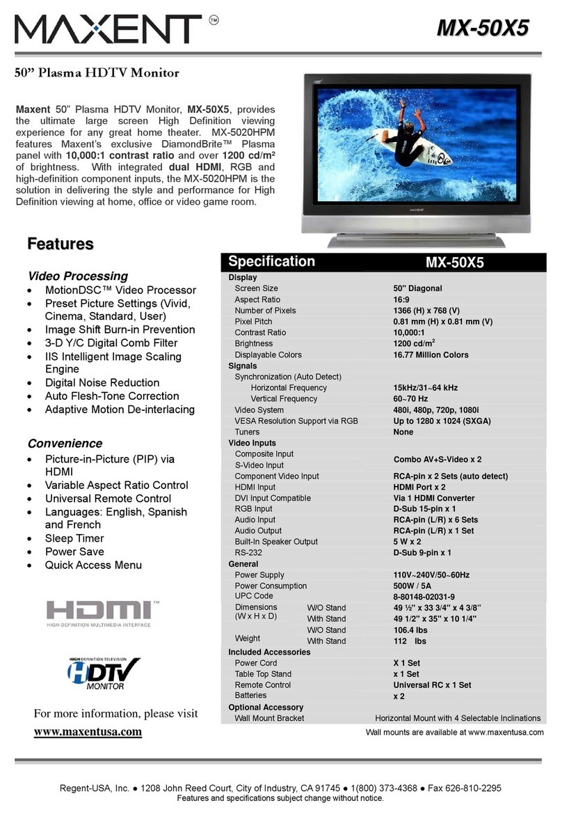
Maxent MX-42VM7 specification

Maxent

Maxent MX-42VM7 specification

Hyundai Q421H user guide

Hyundai

Hyundai Q421H user guide

Samsung HPT4254X/XAA Service manual

Samsung

Samsung HPT4254X/XAA Service manual

Hitachi P42A01 user manual

Hitachi

Hitachi P42A01 user manual

Samsung PE43H4500AW user manual

Samsung

Samsung PE43H4500AW user manual

Samsung PN50A550 user manual

Samsung

Samsung PN50A550 user manual

Prima PH-42FB7 Service manual

Prima

Prima PH-42FB7 Service manual

NEC 42XP10 - PlasmaSync - 42" Plasma Panel user manual

NEC

NEC 42XP10 - PlasmaSync - 42" Plasma Panel user manual

Philips Epic 50PF9966 Technical specifications

Philips

Philips Epic 50PF9966 Technical specifications

Samsung Series 4+ user manual

Samsung

Samsung Series 4+ user manual

LG RU-42PX10 owner's manual

LG

LG RU-42PX10 owner's manual

Haier HP32R owner's manual

Haier

Haier HP32R owner's manual

Samsung PN51E530 user manual

Samsung

Samsung PN51E530 user manual

manuals.online logo
manuals.online logoBrands
  • About & Mission
  • Contact us
  • Privacy Policy
  • Terms and Conditions

Copyright 2025 Manuals.Online. All Rights Reserved.