manuals.online logo
Brands
  1. Home
  2. •
  3. Brands
  4. •
  5. Panasonic
  6. •
  7. TV DVD Combo
  8. •
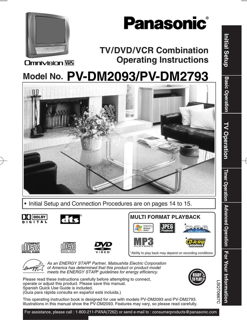
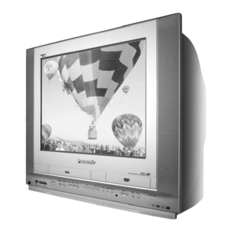
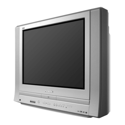
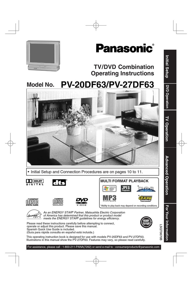
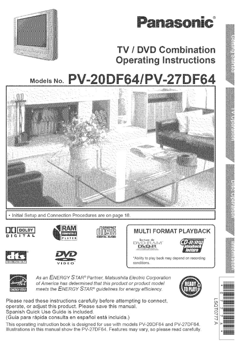
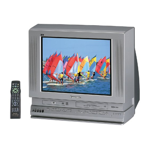
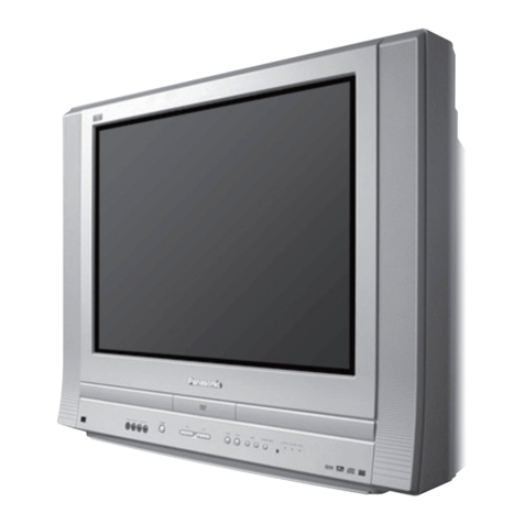
  9. Panasonic PV 20DF63 User manual

Panasonic PV 20DF63 User manual

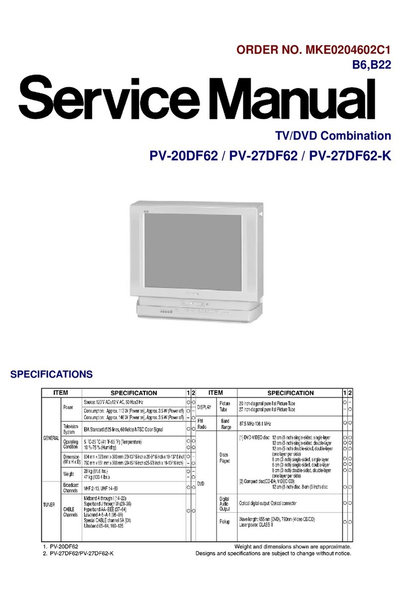
ORDERNO. MKE0303602C1
B6, B22
TV/DVDCombination
PV-20DF63 / PV-27DF63
SPECIFICATIONS
1
1. SAFETYPRECAUTIONS
1.1. GENERALGUIDELINES
1. IMPORTANTSAFETYNOTICE
Therearespecial components usedinthisequipmentwhichare
importantforsafety. These parts aremarkedbyinthe
SchematicDiagrams, CircuitBoardLayout, ExplodedViewsand
ReplacementParts List. Itisessential thatthese critical parts
shouldbereplacedwithmanufacturer’sspecifiedparts toprevent
X-RADIATION, shock, fire, orotherhazards. Donotmodifythe
original design withoutpermission ofmanufacturer.
2. AnIsolation Transformershouldalwaysbeusedduring the
2
servicing ofCombination TV/DVDwhose chassisisnotisolated
fromtheACpowerline. Use atransformerofadequate power
rating as thisprotects thetechnicianfromaccidentsresulting in
personal injuryfromelectrical shocks. Itwill alsoprotect
Combination TV/DVDfrombeing damagedbyaccidental shorting
that mayoccurduring servicing.
3. Whenservicing, observetheoriginal leaddress, especiallythe
leaddress inthehigh voltagecircuits. Ifashortcircuitisfound,
replace all parts whichhavebeenoverheatedordamagedbythe
shortcircuit.
4. Afterservicing, see toitthat all theprotectivedevices suchas
insulation barriers, insulation papers, shield, and isolation R-C
combinationsareproperlyinstalled.
5. Beforeturning thereceiveron, measuretheresistance betweenB+
lineand chassisground. Connect (-) sideofanohmmetertotheB
+lines, and (+)sidetochassisground. Eachlineshouldhave
moreresistance thanspecified,as follows:
B+ Line
MinimumResistance
130 V
110 (Coldchassisground)
28 V
180 (Coldchassisground)
220 V
1k (Coldchassisground)
6. WhentheTVset isnotusedforalong period oftime, unplug the
powercordfromtheACoutlet.
7. Potentials, as high as 33.0kV(Formodel with20 inchCRT), 30.0
kV(Formodel with27 inchCRT)arepresentwhenthisTVset isin
operation. Operation oftheTVset withouttherearcoverinvolves
thedangerofashock hazardfromtheTVset powersupply.
Servicing shouldnotbeattemptedbyanyonewho isnot
thoroughlyfamiliarwiththeprecautionsnecessarywhenworking
on high voltageequipment. Alwaysdischargetheanodeofthe
3
picturetubetotheCRTground ofreceiverbeforehandling thetube.
8. Afterservicing make thefollowing leakagecurrentchecks to
preventthecustomerfrombeing exposedtoshock hazards.
1.2. LEAKAGECURRENTCOLDCHECK
1. Unplug theACcordand connect ajumperbetweenthetwoprongs
on theplug.
2. Forphysicallyoperatedpowerswitches, turnpoweron. Otherwise
skipstep2.
3. Measuretheresistance value, withanohmmeter, betweenthe
jumperedACplug and eachexposedmetalliccabinet parton the
receiver, suchas screwheads, connectors, etc. Whentheexposed
metallicparthas areturnpathtothechassis, thereadingshould
bebetween1M and 12 M . Whentheexposedmetal does not
haveareturnpathtothechassis, thereading must beinfinity.
1.3. LEAKAGECURRENTHOTCHECK
1. Plug theACcorddirectlyintotheACoutlet.
Donotuse aisolation transformerforthischeck.
2. Connect a1.5k , 10 Wresistor, inparallel witha0.15 F
capacitor, betweeneachexposedmetallicparton theset and a
good earthground, as showninFigure1.
3. Use anACvoltmeter, with1k /Vormoresensitivity, tomeasure
thepotential across theresistor.
4. Check eachexposedmetallicpart, and measurethevoltageat
eachpoint.
5. Reverse theACplug intheACoutlet and repeat eachoftheabove
measurements.
6. Thepotential at anypointshouldnotexceed0.75 VRMS.
Aleakagecurrenttester(Simpson Model 229 equivalent) maybe
usedtomake thehotchecks. Leakagecurrentmust notexceed1/2
mA. Incase ameasurementisoutsideofthelimits specified, there
isapossibilityofshock hazard, and thereceivershouldbe
repairedand recheckedbeforeitisreturnedtothecustomer.
Figure1
4
2. X-RADIATION
WARNING:
1. Thepotential source ofX-Radiation inTVsets istheHigh Voltage
section and thepicturetube.
2. Whenusing apicturetubetest fixtureforservice, ensurethat the
fixtureiscapableofhandling 33.0kV(Formodel with20 inch
CRT), 30.0kV(Formodel with27 inchCRT)withoutcausing X-
Radiation.
NOTE:
Itisimportanttouse anaccurate periodicallycalibratedhigh
voltagemeter.
1. Reduce thebrightness tominimum.
2. Set theSERVICEswitchtoSERVICE.
3. MeasuretheHigh Voltage. Themeterreading shouldindicate 31.0
kV±2.0kV(Formodel with20 inchCRT), 28.0kV±1.5kV(Formodel
with27 inchCRT).
Ifthemeterindication isoutoftolerance, immediate service and
correction isrequiredtopreventthepossibilityofpremature
componentfailure.
4. To preventanX-Radiation possibly, itisessential touse the
specifiedpicturetube.
2.1. HORIZONTALOSCILLATORDISABLECIRCUITTEST
SERVICE WARNING:
Thetestmustbemadeas afinal check beforesetisreturnedtothecustomer.
CONFIRMATIONOFX-RAYMOVEMENT
1. Turnoff TVset.
2. Connect thecircuitbelow betweenTP553 and TP554 on theTV
5
MainC.B.A. Figure2
3. Turnon SW1and thenturnon theset. Confirm that thepictureis
on thescreenproperly.
4. Confirm that thepicturegoes outofhorizontal syncwhilegetting
downbyvarying VR.
5. Ifthisdoes notoccur, itmeansthat X-rayprotect circuitisnot
operating. Furtherconfirmation and repairisrequired.
2.2. REPAIRPROCEDURES OFHORIZONTALOSCILLATOR
DISABLECIRCUIT
1. Connect aDC voltmeterbetweencapacitorC513 (+)on theMain
circuitboardand chassisground.
2. Ifapproximately+23.0V(Formodel with20 inchCRT), +21.5V
(Formodel with27 inchCRT)isnotpresentat that pointwhen120
VACisapplied, find thecause. Check R508, R503, R5505, C5507,
C513 and D503.
3. Carefullycheck abovespecifiedparts and relatedcircuits and
parts. Whenthecircuitisrepaired, trythehorizontal oscillator
disablecircuittest again.
2.3. CIRCUITEXPLANATION
2.3.1. HORIZONTALOSCILLATORDISABLE CIRCUIT
Thepositive DC voltage, suppliedfrom theD503 cathodefor monitoring high voltage, isapplied
totheIC5301 Pin11 through R508 and R5504. Undernormal conditions, thevoltageatIC5301 Pin
11 isless thanapprox. 6V. Ifthehigh voltageatFlybackTransformerPin5exceedsthespecified
voltage, thepositive DC voltagewhichissuppliedfrom theD503 cathodealsoincreases. The
increasedvoltageisappliedtoIC5301 Pin11 through R503 and R5504. Duetotheincreased
voltageatIC5301 Pin11,thehorizontal oscillator frequency increases, thepicturegoes outof
horizontal sync, thebeam currentdecreases and thepicturebecomedarkinordertokeepX-
radiation underspecification.
Figure3
6
2.4. LASERPRODUCT
CLASS ILASERPRODUCT
-ThisequipmentiscertifiedtocomplywithDHHSRules 21 CFR
Chapter1, SubchapterJineffect as ofdate ofmanufacture. (Only
forU.S.A.)
Thisequipmentisclassifiedas aClass I(Class 1)level LASERProductand thereisno hazardous
LASERradiation withthesafetyprotection.
Caution:
Use ofcontrolsoradjustments orperformance ofprocedures other
thanthose specifiedhereinmayresultinhazardousradiation
exposure.
Nevertouchtheinternal partsinordertoavoidEXPOSURE TOVISIBLE LASERRADIATION.
Unplug theACpowercord totheequipmentwhenopening thetop cover.
WhenthepowerswitchisOn, do notplace your eyes close tothefrontpanel opening door or the
otheropeningstolookintotheinterior unit.
LASERSpecification
Class Ilevel ALASERProduct(Class 1level ALASERProduct)
WaveLength:
647 -677 nm(at DVD)
775 -815 nm(at CD)
LaserPower:
Nohazardousradiation isemittedwiththesafetyprotection.
2.5. PRECAUTIONOFLASERDIODE
CAUTION:
Thisunitutilizes aclass III alaser. Visiblelaserradiation isemitted
fromtheoptical pickup lenswhentheunitisturnedon:
1. Donotlookdirectlyintothepickup lens.
2. Donotuse optical instruments tolookat thepickup lens.
3. Donotadjust thepreset variableresistoron theoptical pickup.
4. Donotdisassembletheoptical pickup unit.
5. Iftheoptical pickup isreplaced, use themanufactures specified
replacementpickup only.
7
6. Use ofcontrol oradjustmentorperformance ofprocedures other
thanthose specifiedhereinmayresultinhazardousradiation
exposure.
3. PREVENTIONOFELECTROSTATICDISCHARGE
(ESD) TO ELECTROSTATICALLYSENSITIVE (ES)
DEVICES
Somesemiconductor (solidstate)devices canbedamagedeasilybystaticelectricity. Such
componentscommonlyarecalledElectrostaticallySensitive (ES)Devices. Examples oftypical
ES devices areintegratedcircuitsand somefield-effecttransistorsaresemiconductor "chip"
components. Thefollowing techniques shouldbeusedtohelpreduce theincidence of
componentdamagecausedbyelectrostaticdischarge(ESD).
1. Immediatelybeforehandling anysemiconductorcomponentor
semiconductor-equippedassembly, drainoff anyESDon your
bodytouching aknownearthground. Alternatively, obtainand
wearacommerciallyavailabledischarging ESDwrist strap,
whichshouldberemovedforpotential shock reasonspriorto
applying powertotheunitundertest.
2. Afterremoving anelectrical assemblyequippedwithES devices,
place theassemblyon aconductivesurface suchas aluminum
foil, topreventelectrostaticchargebuildup orexposureofthe
assembly.
3. Use onlyagrounded-tipsoldering iron tosolderorunsolderES
devices.
4. Use onlyananti-staticsolderremoval device. Somesolder
removal devices notclassifiedas "anti-static(ESDprotected)"can
generate electrical chargesufficienttodamageES devices.
5. Donotuse freon-propelledchemicals. These cangenerate
electrical charges sufficienttodamageES devices.
6. DonotremoveareplacementES device fromits protective
packageuntil immediatelybeforeyou arereadytoinstall it. (Most
replacementES devices arepackagedwithleadselectrically
shortedtogetherbyconductivefoam, aluminumfoil or
comparableconductivematerial).
7. Immediatelybeforeremoving theprotectivematerial fromthe
8
leadsofareplacementES device, touchtheprotectivematerial to
thechassisorcircuitassemblyintowhichthedevice will be
installed.
CAUTION:
Besureno powerisappliedtothechassisorcircuit, and observe
all othersafetyprecautions.
8. Minimizebodilymotionswhenhandling unpackagedreplacement
ES devices. (Otherwise harmless motion suchas thebrushing
togetherofyourclothes fabricorthelifting ofyourfootfroma
carpetedfloorcangenerate staticelectricity(ESD)sufficientto
damageanES device).
"NOTE toCATV system installer:
Thisreminderisprovidedtocall theCATVsysteminstaller’s
attention toArticle820-40 oftheNECthat provides guidelines for
propergrounding and, inparticular, specifies that thecableground
shall beconnectedtothegrounding systemofthebuilding, as close
tothepointofcableentryas practical."
4. ABOUTLEADFREE SOLDER (PbF)
5. SERVICE NOTES (PLEASE READ)
5.1. SERVICENOTES
5.1.1. SIMPLIFIEDFAULT FINDINGDATA
SimplifiedSelf-DiagnosticSystem facilitates finding thecause ofthefault. Communication for I2C
buscodewill bedisplayedon TV screen.
TheSimplifiedFaultfinding dataisstoredintheMemoryIC(IC6004). Thisdataisclearedafterit
9
isdisplayed, and thenthePOWERbutton ispressedback on.
1. Withpowerturnedoff, press PLAYand SKIP+buttonson theunit
togetherforover3seconds. Fig. 1-1
2. TVpowercomes on and theunitgoes intoservice mode.
Communication forI2Cbuscodewill bedisplayed.
Fig. 1-2
Fig. 1-3
3. Press anyoperation button exceptforPOWER, CH UP, CH DOWN,
LIGHTorDSS CABLEbuttonson eithertheunit, ortheremote to
detect that akeyhas beenpressed. "0"will bedisplayedonly
whenkeyisdetected.
Fig. 1-4
10
5.1.2. USAGE SCREENMODE
Thisfunction isdisplayedon theTV monitor:
-thetotal elapsed"Poweron"time(indays)
-thetotal elapsed"DVDplay"time(inhours).
1. Withpowerturned, press STOPbutton ofoperation panel on the
unitand 7keyon theremote together.
TheUSAGESCREENwill bedisplayedon theTVMonitorofthe
unit.
Fig. 3
Note:
1. Afterreplacing theDVDUnit, press ADD/DLT button on remote in
thismode. OnlyTotal elapsedtime"DVDPlay"time(inhours) will
beclearedto0.
2. To release fromUsageScreenMode, press anyoperation button
orinsertacassette tapeinthismode. Theunitwill returnto
normal operation mode.
5.1.3. GROUNDINGFORELECTROSTATICBREAKDOWN
Prevention
1. Humanbodygrounding
Use theantistaticwrist straptodischargethestaticelectricity
fromyourbody.
2. Worktablegrounding
Putaconductivematerial (sheet) orsteel sheet on thearea where
theoptical pickup isplacedand ground thesheet.
Caution:
11
Thestaticelectricityofyourclothes will notbegroundedthrough
thewrist strap. Sotake carenottolet yourclothes touchtheoptical
pickup. Fig. 4
5.1.4. METHODFOREJECTINGTHE DVDTRAY MANUALLY
1. InsertaScrewdriverorsimilarobject intotheEject hole.
2. Press itgently, and thenpull theTrayfullyout.
Fig. 5
5.1.5. SERVICE POSITION
5.1.5.1. Service Position
CAUTION:
HOTCIRCUIT(Primarycircuit) exists on theTVMainC.B.A.
Use extremecaretopreventaccidental shock whenservicing.
5.1.5.1.1. Service Position (1)
1. RemovetheRearCoverand theDVDAss'y.
2. RemovethePCB HolderPiece fromtheBottomFrame.
12
Fig. 6-1-1
3. InordertostabilizetheTVMainC.B.A. and theTunerMainC.B.A.,
attachthePCB HolderPiece totheC.B.A.s.
Fig. 6-1-2
5.1.5.1.2. Service Position (2)
Fig. 6-2
5.1.5.1.3. Service Position (3)
InService Position (3), theDVDMainC.B.A. withoutExtension Cables canbeperformed.
Fig. 6-3
13
5.1.6. HOTCIRCUIT
Primarycircuitexistson theTV MainC.B.A.
Thiscircuitisidentifiedas " HOT" on theC.B.A. and intheService Manual. Use extremecareto
preventaccidental shock whenservicing.
5.1.7. F.P.C. CONNECTIONNOTE
5.1.7.1. F.P.C. betweentheDVDUnit(DVDMainC.B.A.)and theMainC.B.A.
Becareful withthedirection ofF.P.C. toconnector as shown.
Fig. 7
14
5.1.8. WIRE AND LEAD POSITIONDIAGRAM
Fig. 8
15
5.1.9. HOWTORESETALL COMBINATIONTV/DVDMEMORY FUNCTIONS
Toreset(clear)theselectlanguage, channel autosetand setclock functionstotheirinitial
poweron condition, holddownthePLAYand SKIP-buttonsofoperation panel on theunit
togetherfor morethan5seconds.
Powerwill shutoff.
5.1.10. HOWTOCONFIRMAUTOCLOCK SETFEATURE
1. Connect anRFcablefromtheoutputofoneunittotheinputofthe
test unit.
2. Select corresponding RFchannels.
3. Playback arecording ofP.B.S. channel including clock set data
16
and confirm thisfeature.
5.1.11. VARIABLE VOLTAGE ISOLATIONTRANSFORMER
AnIsolation Transformershouldalways beusedduring theservicing ofCombination TV/DVD
whose chassisisnotisolatedfrom theACpowerline. Use atransformerofadequatepower
rating as thisprotectsthetechnicianfrom accidentsresultinginpersonal injuryfrom electrical
shocks. Itwill alsoprotectCombination TV/DVDfrom being damagedbyaccidental shorting that
may occur during servicing.
Also, whentroubleshooting theabove typeofPowerSupplyCircuit, avariableisolation
transformerisrequiredinordertoincrease theinputvoltageslowly.
5.1.12. SPECIALNOTE
All integratedcircuitsand manyothersemiconductor devices areelectrostaticallysensitive and
thereforerequirethespecial handling techniques describedunderthe"ELECTROSTATICALLY
SENSITIVE (ES)DEVICES" section ofthisservice manual.
5.1.13. MODELNO. IDENTIFICATIONMARK
Use Marks showninthechartbelowtodistinguishthedifferentmodelsincludedinthisService
Manual.
6. DISASSEMBLY/ASSEMBLYPROCEDURES
6.1. CABINETSECTION
6.1.1. DisassemblyFlowchart
Perform all disassemblyprocedures intheorderdescribedinthe"DisassemblyFlowchart"
shownbelow. Whenreassembling, use thereverse procedure.
CAUTION:
Disconnect ACplug beforedisassembly.
Fig. D1
17
Fig. D2
18
Fig. D3
19
6.1.1.1. Notes inchart
1. Removal ofDVDAss’y Fig. D4
20

Other manuals for PV 20DF63

3

This manual suits for next models

1

Other Panasonic TV DVD Combo manuals

Panasonic PV27D52 - TV/DVD COMBO - MULTI LANGUAGE User manual

Panasonic

Panasonic PV27D52 - TV/DVD COMBO - MULTI LANGUAGE User manual

Panasonic PV-20DF25-K User manual

Panasonic

Panasonic PV-20DF25-K User manual

Panasonic PVDM2791 - MONITOR/DVD COMBO User manual

Panasonic

Panasonic PVDM2791 - MONITOR/DVD COMBO User manual

Panasonic CT-20DC50 User manual

Panasonic

Panasonic CT-20DC50 User manual

Panasonic OmniVision PV-DM2092-K User manual

Panasonic

Panasonic OmniVision PV-DM2092-K User manual

Panasonic PV27DF64 - DVD TV COMBO User manual

Panasonic

Panasonic PV27DF64 - DVD TV COMBO User manual

Panasonic PVDM2092 - MONITOR/DVD COMBO User manual

Panasonic

Panasonic PVDM2092 - MONITOR/DVD COMBO User manual

Panasonic PV27DF5 - DVD/TV UNIT User manual

Panasonic

Panasonic PV27DF5 - DVD/TV UNIT User manual

Panasonic PV-27DF62K User manual

Panasonic

Panasonic PV-27DF62K User manual

Panasonic PV DF2004 User manual

Panasonic

Panasonic PV DF2004 User manual

Panasonic PV 20D53 User manual

Panasonic

Panasonic PV 20D53 User manual

Panasonic V-DF2702-K User manual

Panasonic

Panasonic V-DF2702-K User manual
Panasonic PT-61XF70 User manual

Panasonic

Panasonic PT-61XF70 User manual

Panasonic TFTV5585M User manual

Panasonic

Panasonic TFTV5585M User manual

Panasonic PV9D53 - MONITOR/DVD COMBO User manual

Panasonic

Panasonic PV9D53 - MONITOR/DVD COMBO User manual

Panasonic PVDM2793 - TV/VCR/DVD COMBO User manual
Panasonic

Panasonic PVDM2793 - TV/VCR/DVD COMBO User manual

Panasonic PV 20DF63 User manual

Panasonic

Panasonic PV 20DF63 User manual
Panasonic TFTV5025FL User manual

Panasonic

Panasonic TFTV5025FL User manual

Panasonic PV-27DF25ND User manual

Panasonic

Panasonic PV-27DF25ND User manual

Panasonic TX-15LV1F User manual

Panasonic

Panasonic TX-15LV1F User manual

Panasonic OmniVision PV-DF2036M User manual

Panasonic

Panasonic OmniVision PV-DF2036M User manual

Panasonic PVDF204 - DVD/VCR/TV COM User manual

Panasonic

Panasonic PVDF204 - DVD/VCR/TV COM User manual

Panasonic PV 20D53 User manual

Panasonic

Panasonic PV 20D53 User manual

Panasonic Omnivision PV-DF2002 User manual

Panasonic

Panasonic Omnivision PV-DF2002 User manual

Popular TV DVD Combo manuals by other brands

Akura APLDVD21668 FD quick start guide

Akura

Akura APLDVD21668 FD quick start guide

JVC LT-22DD22J operating instructions

JVC

JVC LT-22DD22J operating instructions

Symphonic SC520FDG owner's manual

Symphonic

Symphonic SC520FDG owner's manual

Insignia NS-24LD100A13 Quick setup guide

Insignia

Insignia NS-24LD100A13 Quick setup guide

Sylvania SSC727B owner's manual

Sylvania

Sylvania SSC727B owner's manual

Magnavox 26MD350B - owner's manual

Magnavox

Magnavox 26MD350B - owner's manual

Insignia NS-14FCT user guide

Insignia

Insignia NS-14FCT user guide

AEG CTV 4894 DVB-T/DVD instruction manual

AEG

AEG CTV 4894 DVB-T/DVD instruction manual

Toshiba MD14H63 owner's manual

Toshiba

Toshiba MD14H63 owner's manual

Denver TVD-1413 user manual

Denver

Denver TVD-1413 user manual

UMC L22/1C-GB-TCD-UK user guide

UMC

UMC L22/1C-GB-TCD-UK user guide

Toshiba 19SLV411U owner's manual

Toshiba

Toshiba 19SLV411U owner's manual

Kogan 6 Series quick start guide

Kogan

Kogan 6 Series quick start guide

Disney Cars C1320PTVD user guide

Disney

Disney Cars C1320PTVD user guide

RCA L40HD33D - LCD/DVD Combo HDTV Guide de l'utilisateur

RCA

RCA L40HD33D - LCD/DVD Combo HDTV Guide de l'utilisateur

Toshiba 15LV505-T owner's manual

Toshiba

Toshiba 15LV505-T owner's manual

Toshiba 23HLV85 - 23" LCD TV owner's manual

Toshiba

Toshiba 23HLV85 - 23" LCD TV owner's manual

LG RHT297H owner's manual

LG

LG RHT297H owner's manual

manuals.online logo
manuals.online logoBrands
  • About & Mission
  • Contact us
  • Privacy Policy
  • Terms and Conditions

Copyright 2025 Manuals.Online. All Rights Reserved.