Installation and servicing manual
Shell & Tube Cooler
8Parker Hannin Corporation
Hydraulics Group
Catalogue HY10-6014-UM/CN
Preventive Maintenance/Procedures
4.4 Before Operation
4.4.1 PIPE INSTALLATION CHECKUP
Ensure that the pipe is installed properly prior to
operating the equipment. Oil and cooling water
may leak when the pipe is not installed properly.
4.4.2 COOLING WATER SUPPLY
Check that the cooling water is being supplied prior to use.
No heat exchanger effect will take place if the cooling water
is not supplied. See PRIOR TO INSTALLATION for cooling
water quality.
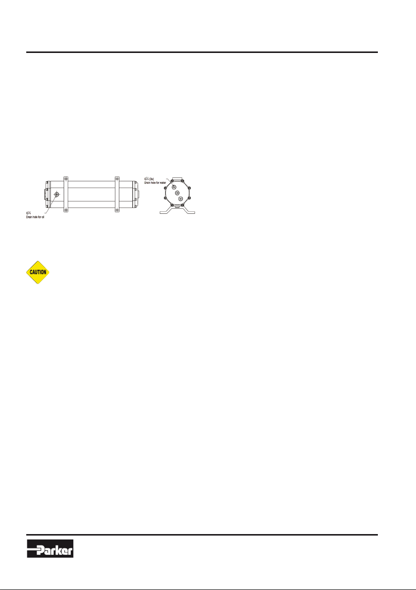
4.4.3 DRAIN PLUG
Ensure that water and oil drain plugs at the bottom are
closed prior to operating.
4.5 Operation
1. Ensure the entire system is clean before starting
operation to prevent clogging of tubes or shell side.
2. Open vent connections before starting up. A
heat exchanger is a pressure vessel designed
for operation at certain specific limits of pressure
and temperature. The cooling or process system,
which includes the heat exchanger, must be
safeguarded with safety valves and controls so
that these heat exchanger design conditions are
not exceeded. All operating personnel should be
made aware of these specific design pressures and
temperatures.
3. Start Operating the system. If in doubt, contact
Parker OLAER Suzhou office for specific instructions.
4. After the system is completely filled with the
operating fluids and all air has been vented, close all
manual vent connections.
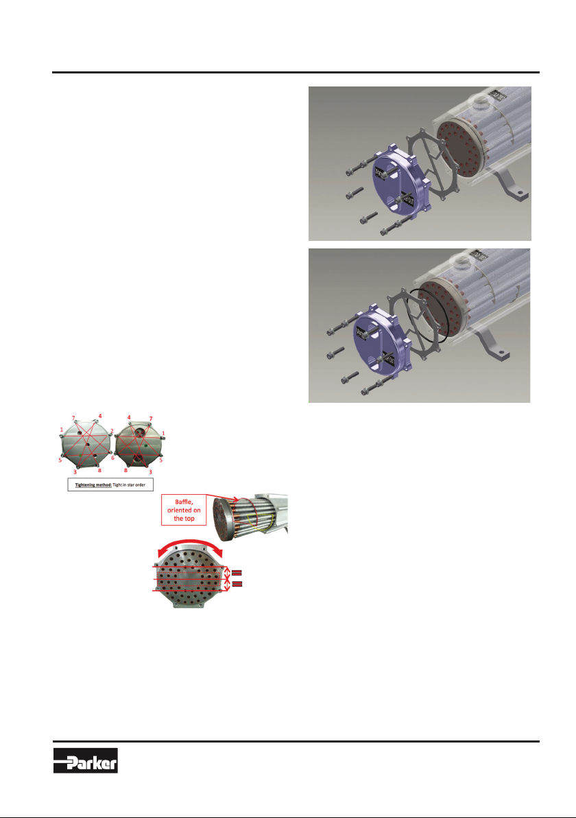
5. Bolting on all gasket or packed joints should be
retightened after the heat exchanger has reached
operating temperatures to prevent leaks and gasket
failures. Refer to tightening torque table in annex of
this shell and tube cooler manual.
6. Do not operate the heat exchanger under pressure
and temperature conditions in excess of those
specified on the name plate.
7. Drain all fluids when shutting down to eliminate
possible freezing and corrosion.
8. In all installation there should be no pulstation of
fluids since this cause vibration and will result in
reduced operating life.
5. Preventive Maintenance
5.1 Inspection and Cleaning
External and internal inspection and cleaning by
disassembling the shell and tube cooler are required every 6
months if used on application using clean fluid, as per water
quality table in annex of the shell and tube manual, and
equipped with filtration system.
For coolant from other origins, external and internal
inspection and cleaning by disassembling the shell and tube
cooler are required every 4 months.
5.2 Cleaning
During the inspection and cleaning process at the required
time intervals, check the cooler carefully for any sign of wear
or corrosion (internal and external) that could lead to product
malfunctioning or leakage.
Any component presenting any sign of advanced wear should be
analyzed carefully and replaced if necessary, to ensure product
function and reliability.
5.3 Replacable Components
Shell and tube cooler components subject to wear and that
potentially need to be replaced during preventive maintenance
process are the following : tube bundle, floating Cover and
stationery cover, O-Ring, Gaskets.
Refer to the product exploded view in annex of this manual,
or to the product technical specifications for components part
number.
5.4 Record
Maintenance tasks performed on the shell and tube cooler shall
be recorded and available at any time.
Product maintenance record should be provided in case of faulty
product or warranty claim.
6. Maintenance Procedures
6.1 Remove O-Ring or Gasket
Ensure to remove all the pressure in the shell and
tube heat exchanger before disconnecting any bolt,
connection, plug or cover.
6.1.1 WHEN TO REMOVE
• O-Ring or gasket may be needed to be replaced when a
leak occurs arround them.
• Replace O-Ring and gasket during periodic pipe cleaning.
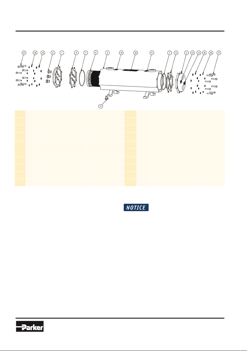
6.1.2 HOW TO REMOVE
For the name of the components, please refer to “3. Product
Parts Name”.
1. Unscrew the bolts, the spring washers and washers.
2. Remove the bolts, the spring washers and washers.
3. Remove the covers.
4. Remove the gaskets (if you only need to change the
gaskets, change them and repeat the above steps
reversely, 4 to 1).
5. Beat with a rubber hammer on the tube sheet on one
side until the other side is out of the shell. DO NOT USE A
HARD TOOL. This will result in tube damage and result in
cooler leakage.
6. Remove the first O-Ring.
7. Beat on the other side (on the tube sheet) until tube
bundle is out of the shell.
8. Remove the second O-Ring.
9. Change them and repeat the above steps reversely, 8 to 1
steps reversely (in order of 1, 2,3 and 4) to
complete assembling.