PARS EcoTech S.L. WM 6.0 User manual

PARS EcoTech
WM 6.0 Evaporative Cooler
Owner’s manual

Table of Contents:
General information……........................................................2
Introduction............................................................................3
Unit operation.........................................................................3
Please note.............................................................................3
Before starting........................................................................4
Installation requirements........................................................6
External fixing of the unit........................................................7
Internal fixing of the unit.........................................................8
Problem solving....................................................................10
Water connection..................................................................12
Commissioning.....................................................................12
Maintenance..........................................................................13
Filter pads..............................................................................15
Water tank..............................................................................15
Water distributor.....................................................................15
Water level/Float valve...........................................................16
Electrical................................................................................16
Maintenance Planner.............................................................17
Specifications........................................................................18
Specifications:
Airflow
6000 m3/h
Window section
550*550*260 mm
External cabinet
1180*860*250 mm
Net weight
35 kg
Power supply
220 V / 50 Hz
Power consumption
0.25 kw
Motor
0.15 kw / 3 Speed
Noise
60 dB
Packed size
1220*900*420 mm
1
18

Maintenance planner:
ALL MAINTENANCE CAN ONLY BE PERFORMED BY A QUALIFIED SERVICE PERSON.
Service
Should list
1st
Year
2nd
Year
3rd
Year
4th
Year
5th
Year
PRESEASON
CHECK
Check quality of filters
Check fan & pump
Fill unit with water
Start unit
FIRST
MIDSEASON
SERVICE
Check and clean filters
Drain, clean and refill water tray
Check filters
Check unit operates correctly
SECOND
MIDSEASON
SERVICE
Check and clean filters
Drain, clean and refill water tray
Check strainers and filters
Check unit operates correctly
END OF
SEASON
SERVICE AND
SHUT DOWN
Turn off water supply
Drain and clean unit
Leave drain plug removed
Check motor and pump and
spray with a water
displacement lubricant
GENERAL INFORMATION
Thank you for purchasing a quality Evaporative Cooler, We care about your safety
and would ask you to spend a few minutes reading these simple instructions before
installing or operating this product.
Safety
Read carefully all of these instructions prior to installing and operating the unit.
Read and Save these Instructions .Do not throw these Instructions away
Installations of this cooler in any manner not prescribed by these instructions
could cause a safety issue and WILL void any warranty
Use only with a 220v 50Hz single phase grounded outlet.
Unplug the cooler and turn off the machine when installing, servicing or
cleaning.
Do not operate cooler with Rear filter panel removed.
Do not operate cooler with a damaged cord, plug or other component.
Do not run the power cord under carpet or other floor covering
Do not sue the cooler with an improperly grounded outlet.
Do not alter or modify this cooler.
Do not allow children to install, operate or service this cooler.
WARNING: To reduce the risk of fire or electric shock, do not use this product
with any solid state speed control device.
Use only qualified electricians for replacement or servicing of switches, or
electrical motors.
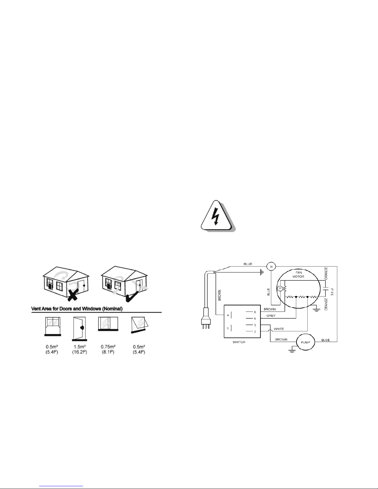
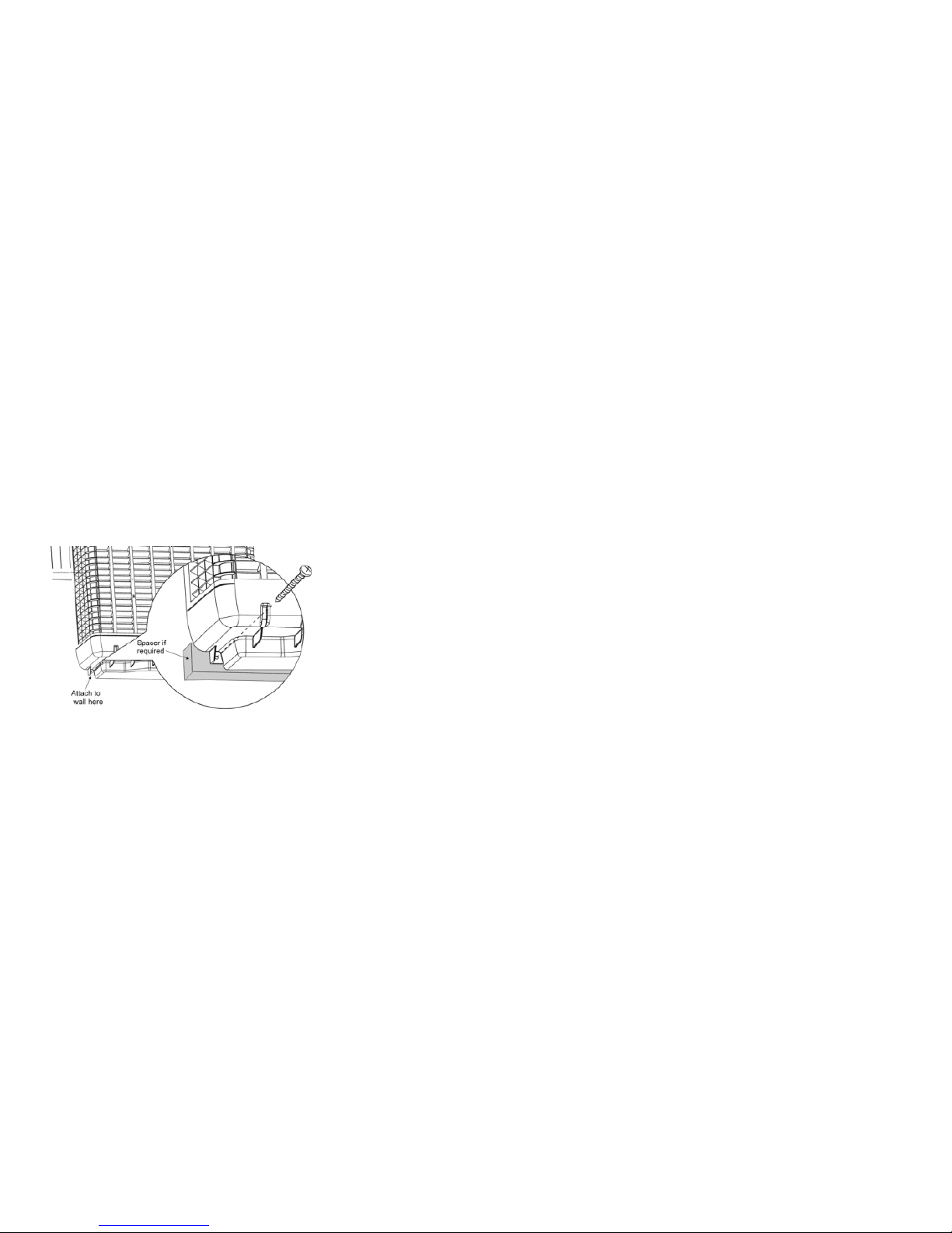
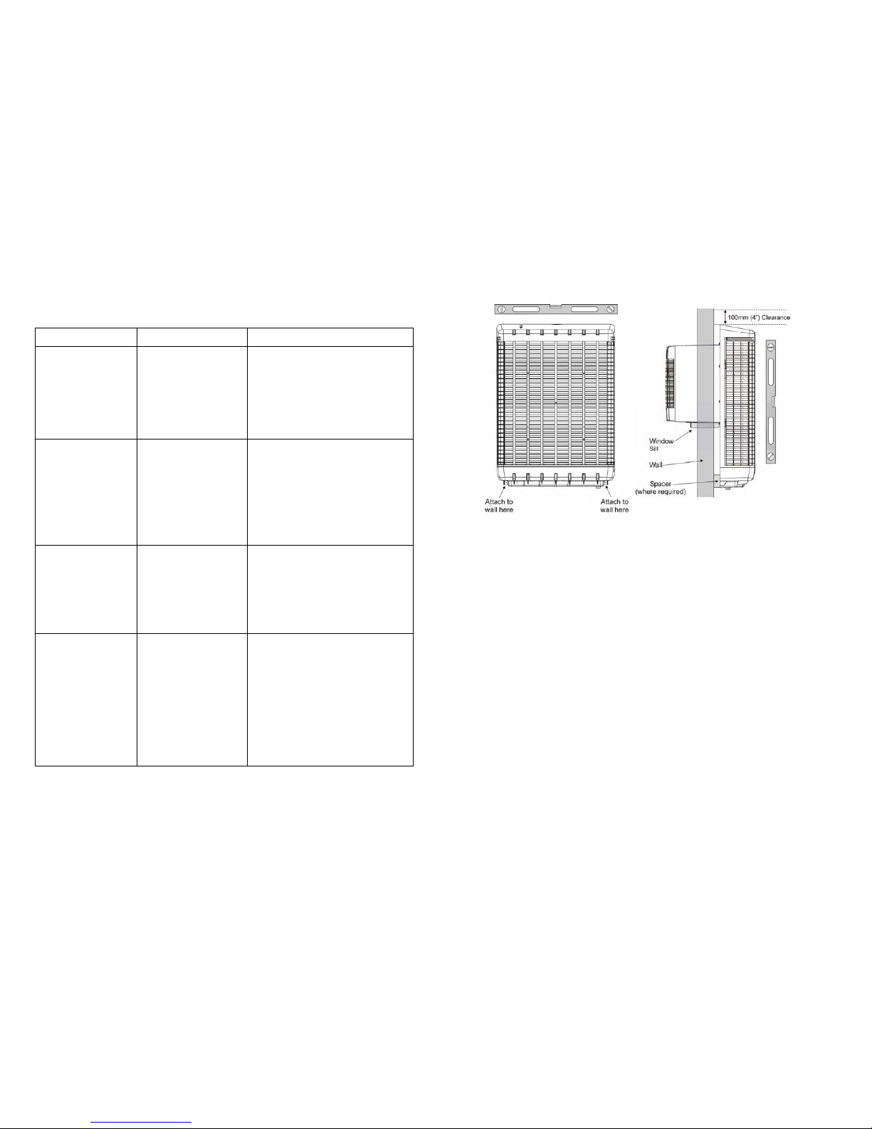
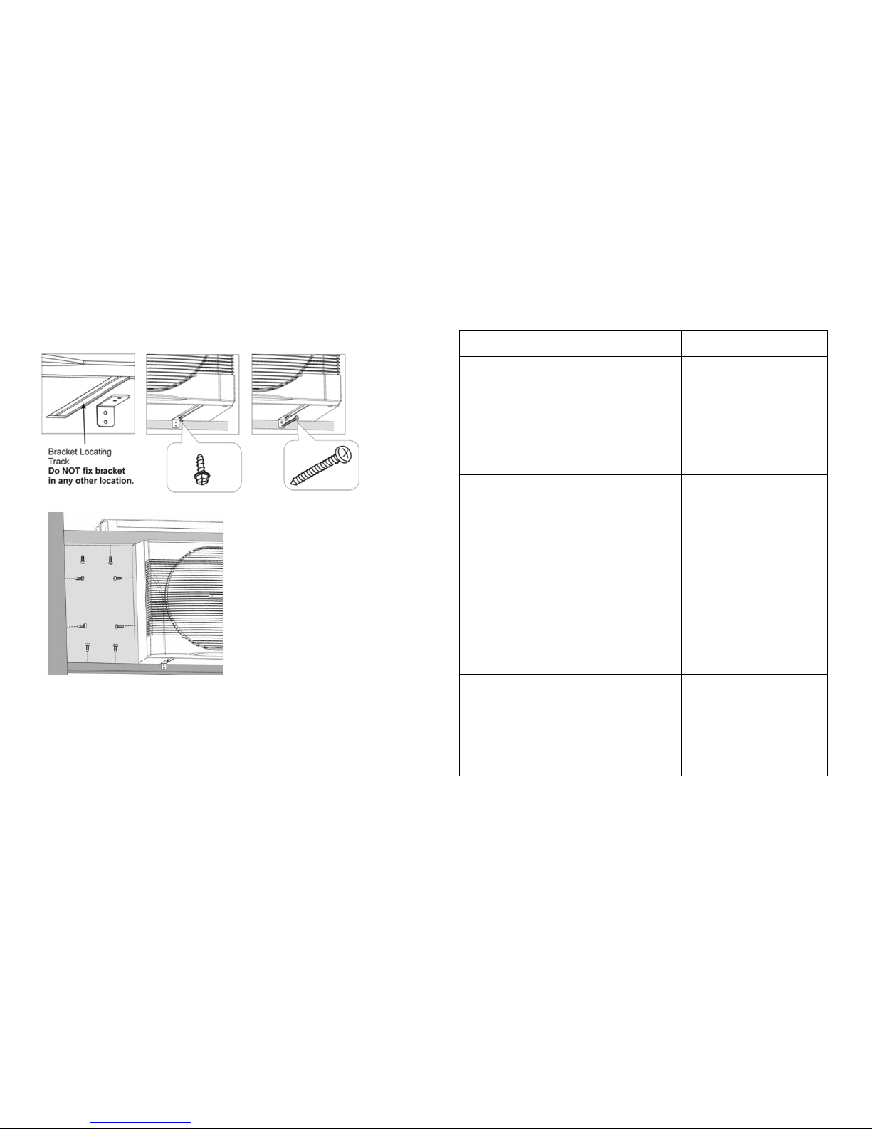
This Window Mounted Cooler is suitable for installation in windows (either sash
hung or sliding) with a minimum opening width of 550 mm and height of 550
mm please ensure that the directions for correct mounting are adhered to for
the SAFE operation of this cooler.
Ensure there is a minimum 100mm clearance above the external cabinet for
maintenance purposes.
17
2

GENERAL
Introduction:
Your evaporative cooler is engineered to meet the rigors of harsh
environments .Used and maintained in accordance with this manual, it will provide
you with years of quiet, cool and environmentally friendly operation. Please take
the time to read this manual.
The principal of your unit is to introduce fresh air, which is washed through the filter
pads to provided cool fresh air .the warm stale air within the room is forced out by
the cool air through open doors or windows
Unit Operation:
It is essential for successful operation of the evaporative cooler that there be
sufficient free air openings in the room to be cooled approximately 05 square
meter .Open doors and windows will usually provide this as per the diagrams
below.
Please note: it is important for good ventilation that doors or windows are not
open on the windward side of the house.
Water Level / Float Valve
The float valve is a mechanical type and is factory set. If the valve is leaking, it may
require replacement.
Note: Water connection line to float valve must be flushed before connecting.
Motor and Fan
Check that the fan spins freely and that there is no build up on the blades. Check
the motor for corrosion and spray with an anti corrosive agent if necessary.
ELECTRICAL
No general maintenance is required to the electrical system.
Electrical connections and maintenance should only be carried out by a
qualified electrician.
3
16

STEP 4: (Optional)
The pump hose will be attached to rear filter panel. Should the hose come off
during removal of rear filter panel or be removed for servicing the filters, care
should be taken to re-attach the hose and snap lock clamp before replacing rear
filter panel.
IMPORTANT: The rotation of the snap lock clamp must be correct (see diagram
above) to refit the rear filter panel assembly.
-----------------------------------------------------------
Filter Pads
Visually check filter pads for damage or blockage. Gently hose down pads from
both sides to remove any build up of salts, dust and pollen. In dusty areas more
regular cleaning is recommended. Check the water distributor, making sure it is
clear and free from blockage. Failure to do so may lead to uneven water
distribution and therefore less efficient operation.
Water Tank
It is important to keep the water tank clean and free from sediment and algae
growth.
Using a small soft bristle brush, brush all surfaces in the tank while it is full of water
Turn off the water inlet to the unit (an isolation valve should be fitted to the water
inlet before the float valve or at the water supply faucet). Drain the tank by undoing
the external overflow fitting lock nut and removing the overflow fitting. After refilling
it may be necessary to repeat this procedure if the tank is very dirty.
Water Distributor
Check the water distribution system for blockage. Check the delivery tube for kinks
or holes.
Before Starting
Always ensure that there is another open window or door through which the
air can exhaust to other parts of the house. Refer page 5 correct operation
and ventilation.
Ensure that the filters are kept clean.
Ensure that the water to the cooler is turned on.
Ensure the plug is connected to a 220V 50Hz single phase grounded
appliance socket on the inside of the house and turned on.
IMPORTANT. After the first 10 hours of operation in COOL mode, the
water must be drained from the unit water tank to remove any new
product residuals. This process must be repeated after a further 10 hours
of COOL mode operation.
Press the button “ ” in the standby, the Unit starts, the factory default
setting: Fan works at minimum speed, cooling mode, Auto Swing works. The
unit is turned off when the “ ” is pressed, the temperature is shown
after the unit is turned off.
The indicator lights shows “Red”color when the unit is plugged into
electricity, the light indicator show “Green” when the unit work at cooling
mode.
15
4

1. Turn On/Off: Press the button “ ” in the standby, the Unit starts, the
factory default settings: Fan works at minimum speed, cooling mode, Auto Swing
works. The unit‘s memory system keeps the fan speed, mode for previous running
mode. The unit is turned off when the “ ” is pressed, the Clock show the
time.
2. Fan Speed control: The coolers can be operated in three speed when pressing
the button of & , the speed volume is shown in the indicator of remote
control.
3. Mode: The cooler can be operated in either of 2 modes, COOL or FAN. When
the cooler is running in FAN model, press the button, the unit will run in
COOL mode, and the cooler will run in a minimum speed in 30 seconds, then the
motor runs at its previous speed, the fan speed indicator keeps same speed
volume.
4. Auto Swing: Press the button, the air diffuser is swinging, the indicator shows in
the remote control.
STEP 1: Remove Rear filter panel fixing screws (4 off).
STEP 2: Lift the Rear filter panel in a vertical fashion 3”or 75mm.
STEP 3: Pull rear filter panel away from unit.
5
14

• Press the button “COOL” in the remote control and operate the three speed fan
and pump.
• Leaving the unit in the COOL mode, check that a constant small stream of bleed
off. Water is coming from the overflow tube. This bleed off is designed to reduce
mineral build up on filter pads.
• You may notice a wet paper smell as the water circulates around the filter pads.
This is normal during the commissioning phase and at the beginning of each
season when the unit is operated after the winter break. It will only last for a short
time.
Maintenance:
ALL MAINTENANCE CAN ONLY BE PERFORMED BY A QUALIFIED
SERVICE PERSON.
Before commencing any maintenance work on your unit, ensure it is
disconnected from the power supply.
Note: It is essential that your evaporative cooler is maintained in accordance with
this manual.
Failure to do so will affect the life of the product and reduce the level of efficiency.
THIS MANUAL CONTAINS A 5 YEAR MAINTENANCE PLANNER TO USE IN
CONJUNCTION WITH THESE INSTRUCTIONS. (See page 14).
5. Drain: Press button “drain”, the unit aromatically turn off the motor, water pump,
swing and the drain valve is turned on. The water flushes into the water tank within
120 seconds and the drain valve is open at the same time. The drain valve closes
after 60 seconds. The water then flushes into the water tanks unit the tank is full
with water and the water inlet valve closes. The unit is in standby.
INSTALLATION REQUIREMENTS
Tools
- Drill (Power or Cordless)
- Phillips Head Screw Driver
- Drill bits for drilling pilot holes into window frame. 1/8" (3.2mm) drill or appropriate
for size of screw used.
- Philips Head Screws for affixing Window Infill Panel
Materials Required (Not supplied)
- Copper or plastic high pressure water pipe for mains water supply.
- 840mm (33¡±) of suitable spacer material (if required)
INSTALLATION
Note that it is not necessary to remove the Rear filter panel from the unit for
installation.
Do not connect the power to the cooler until the installation is complete.
13
6

External Fixing Of the Unit
Ensure that the location chosen to mount the cooler is strong enough to
support the operating weight of the unit. The unit is nominal operating weight
is
42 kg.
Ensure that the window opening is large enough for the neck of the cooler
(nominally 550mm high by 650mm wide).
Ensure there is a minimum 100mm clearance above the external cabinet for
maintenance purposes.
Position the cooler through the window (two or more people will be required
for this) so that the unit is hard up against the outside wall of the house.
Note that if the cooler does not fit hard up against the outside wall (e.g. a
protruding timber or brick window sill), utilize a spacer block of wood (not
provided) which must be attached to the wall (the unit is then fixed to this wood).
Ensure there is a 100mm clearance above the unit so the rear panel can be
remove for service.
Ensure that the unit is installed level in the vertical and horizontal positions as
illustrated, prior to fixing the cooler.
Water Connection
Fit mains water supply line to the float valve installed. The float valve connection is
½” BSP.
Note: Water connection line to float valve must be flushed before connecting.
The overflow is factory fitted. The bleed hose protruding through the overflow
fitting SHOULD bleed water during normal operation at a rate between 6 –12 Liters
per hour.
This is normal and is designed to preserve the quality of the Cooler and Cooling
efficiency of the Unit. If required this Bleed water can be plumbed away using
standard 'over-the-counter' garden hose and fittings.
The float valve is factory set and should require no further adjustment at time of
installation (see page 13 if adjustment is required).
Your cooler is now ready for commissioning.
Commissioning
• Check that another door or window in the room is open to allow air to exhaust to
other parts of the house.
• Turn the water supply to the cooler on.
• Plug the cooler into a 220V 50Hz single phase grounded appliance socket on
the inside of the house and switch the socket on.
• Turn the unit on to FAN mode and check the operation of the three speed.
7
12

Problem Solving
PROBLEM
PROBABLE CAUSE
REMEDY
Unit fails to start
A-Power Failure
B-Tripped Circuit
Breaker
C-Blown Fuse
D-Electrical Fault
A-Wait for power to be turned on.
B-Reset circuit breaker
C-Replace
D-Dealer Service
Filter Pads not
wetting
A-Pump Seized
B-Electrical fault with
pump.
C-Low voltage in
your area
A-Refer to Maintenance page.
See Pump section.
B-Dealer Service
C-Remove water restrictor at
bleed tee. See page 14.
Water leaking from
overflow
A-Float Valve Leaking
B-Drain from Pads
A-Check adjustment or replace
float valve if necessary
B-Normal Operation - adjust float
level
Water Droplets in
air stream
A-Loose Delivery
Tube
B-Break in tubing
C-Pump appears to
deliver excessive
water to pads
D-Bleed nozzle is
blocked
A-Check and tighten
B-Replace as necessary
C-Check the condition of the filter
pad. Wash if pad shows heavy
build up of minerals
D-Clean bleed nozzle
Use the two ‘Wall mate’ screws provided to fix the cooler to the outside of the
house if a “stucco-type “wall is being used. (Note that if the unit is not hard up
against the wall, these fixing screws will go into the spacer block already installed).
For solid walls, brick or masonry, use suitable masonry lag anchors.
Place the unit in position, mark screw positions, remove unit then drill pilot holes
for timber walls (3.2mm).
Replace unit in window, fit screws.
Internal Fixing of the Unit
IT IS MANDATORY THAT THE METAL FIXING BRACKETS SUPPLIED ARE
FITTED TO ENSURE A SECURE INSTALLATION.
Utilize the 2 fixing brackets and 4 screws provided as shown in the diagram to
ensure the unit is adequately locked into position.
Ensure that the bracket is aligned within the indicated mounting track area on the
underside of the fan housing ¨C see diagram below.
11
8

Drill 2x1/8¡± (3.2mm) holes and insert screws into unit as per diagram and repeat
for window frame with appropriate screws.
Ensure that the cooler is now fixed rigidly to the house structure.
Close window against unit. Measure the gap of the opening & cut the in-fill panel to
fit in the gap left.
Fit in fill panel with screws (length of screws must not exceed 25mm (1¡±) in
length) and seal any gaps with silicone.
Check that the unit is still level using spirit level on top edge of rear filter panel.
Problem Solving
PROBLEM
PROBABLE CAUSE
REMEDY
Excessive humidity
A-Not enough air flow
B-Inadequate Exhaust
A-Increase fan speed
B-Provide more open area to
exhaust stale air by opening
windows and doors in
adjacent rooms
Inadequate Cooling
A-Dirty Filters
B-Dry Filters
A-Clean
B-Check control set on
COOL mode. Check water
delivery system. Adjust if
necessary.
Unpleasant Odor
A-Unit located near
odor source
B-Algae in water tank
A-Remove source
B-Clean tank and refill with
fresh water.
Rapid formation of
white deposits on
pads
High Mineral Content
Clean filter pad.
More regular maintenance
may be required.
9
10
Table of contents