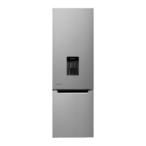
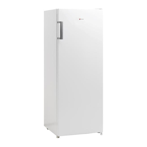
Patrick HPK315NFI User manual

SERVICE MANUAL
Model:
: HPK315NFI
Contents
Specifications ------------------------1
Circuit Diagram-----------------------4
Refrigerant Circuit-------------------6
Replacement of Parts---------------7
Trouble shooting---------------------17

P a g e | 1
PRINTED : JULY’2017 REF NO. COD-002-000062
SERVICE MANUAL Refrigerator
1
Specifications
1-1) Specific parts for specific countries
Item
No.
Model
Destination
Power Source (Voltage-
ac / Hz)
Power Cord
1.
HPK315NFI
Argentina
220-240V 50Hz
Argentina plug

P a g e | 2
PRINTED : JULY’2017 REF NO. COD-002-000062
1-2) Product
Model
HPK315NFI
Classification
2 Doors No Frost
Temperature Control
Mechanic control
Defrost System
Automatic
Drain System
Automatic (Heat by transfer from the Condenser)
Evaporator
Fined Evaporator
Condenser
Pipe Condenser
Insulation
Cabinet
Rigid Polyurethane Foam ( Cyclopentane )
Freezer Door
Rigid Polyurethane Foam ( Cyclopentane )
Refrigerator Door
Rigid Polyurethane Foam ( Cyclopentane )
Refrigerant
R-600A
Refrigerant Charge (g.)
46
Overall Dimension (WxDxH (mm.))
595x 677 x 1650.5
Packing Dimension (WxDxH (mm.))
630x755x1751.5
Net Weight (kg.)
55
Gross Weight (kg.)
61

P a g e | 3
PRINTED : JULY’2017 REF NO. COD-002-000062
1-3) Electrical Parts
Compressor
Model HPK315NFI
ETC95
Electrical data
Input: 220-240V 50Hz
Resistance value
Main :22.04±10%Ω
Aux : 18.36±10% Ω
Overload Protector
Model
BT32-115
Electrical data
Operation Current(25°C): 3.6 A
Operation time: 6~16 S
Reset time: ≥10 S
Operation Temperature: 115±5°C
Reset Temperature: 61±9°C
Min Operation Current(70°C): 0.6~1.0 A
Starting Relay
Model
TY-QZ-003
Electrical data
Normal resistance: 15±20%Ω
Operating time: 0.1~3.5 S
Reset time: ≤150 S
Max Voltage: 350 V,8A
Running Capacitor
Model
CBB65A-2
Electrical data
3µF 50/60HZ 400/450V
Freezer Fan motor
Model
FD-F6110A-5059
Electrical data
Rated Current: 0.048±15%,(AT 25°C)
Input Rated Power: 7.1±15%,(AT 25°C)
Thermal fuse
Model
SF76E
Electrical data
10A 250V
cut-off temperature 77 C
BIMETAL THERMO
Model
S101-DF
Electrical data
Cut off temp: 11±3°C
Cut in temp: 2±4°C
Door switch
Model
D3D-211
Electrical data
250V AC 0.5A T55
Thermostat
Model
WPFE7.5H-L
Electrical data
250VAC, 125 A
Defrost timer
Model
TMDFX05ZH1
Electrical data
Runtime 50Hz: 12.0 hr±6 Min
Defrost 50Hz :6.36± 1.12Min
Lamp
Model
E-14,T20
Electrical data
220V.,10W

P a g e | 4
PRINTED : JULY’2017 REF NO. COD-002-000062
2
Circuit Diagram
Model: 2-1 Circuit Diagram

2-2 Reference wiring diagram
P a g e | 5
PRINTED : JULY’2017
REF NO. COD-002-000062

P a g e | 6
PRINTED : JULY’2017 REF NO. COD-002-000062
3
Refrigerant Circuit

P a g e | 7
PRINTED : JULY’2017 REF NO. COD-002-000062
4
Replacement of Parts
•Unplug the power cord before servicing.
Part Name
Frz Fan Blade.
Operating Procedure
1. Remove Ice Storage Box.
2. Remove Ice Cube Tray Assy.
3. Remove Shelf F.
4. Dig Cover Cap out.
5. Release screws at FF Cover
6.Lift Cover and Fan Cover out.
7. Dig Spring
8. Lift Spring..
9. Pull out Fan Blade from Fan Motor
10. After replacing Fan Blade, reverse the steps above.

P a g e | 8
PRINTED : JULY’2017 REF NO. COD-002-000062
Part Name
Fan Motor.
Operating Procedure
- Follow step 1-10 of replacing Fan Blade.
1. Lift Plate MTG Motor out.
2. Take out socket of Fan Motor.
3. Release screw at Cover A.
4. Pull Cover A from Plate MTG Motor.
5. Pull out Fan Motor from Plate MTG
Motor.
6. After replacing Fan Motor,
reverse the steps above.

P a g e | 9
PRINTED : JULY’2017 REF NO. COD-002-000062
Part Name
Bimetal Thermo.
Operating Procedure
- Follow step 1-10 of replacing Fan Blade.
-Follow step 1-2of replacing Fan Motor.
1. Take out socket of Bimetal Thermo.
2. Cut out Cable Tie from Evaporator
tube.
3. Pull Bimetal Thermo from
Evaporator tube.
4. After replacing Bimetal Thermo, reverse the steps above.
Part Name
Thermal Fuse.
Operating Procedure
- Follow step 1-10 of replacing Fan Blade.
-Follow step 1-2of replacing Fan Motor.
1. Take out socket of Thermal Fuse.
2. Cut out Cable Tie from Evaporator
tube.
3. Pull Thermal Fuse from
Evaporator tube.
4. After replacing Thermal Fuse, reverse the steps above.

P a g e | 10
PRINTED : JULY’2017 REF NO. COD-002-000062
Part Name
Glass Tube Heater.
Operating Procedure
- Follow step 1-10 of replacing Fan Blade.
- Follow step 1-2of replacing Fan Motor.
1. Take out socket of Glass Tube Heater.
2. Take out socket of Glass Tube
Heater.
3. Remove aluminium tape that
cover electrical wire.
4. Hold and lift Evaporator up.
5. Hold Glass Tube Heater at the
rubber connector.
6. After replacing Glass Tube
Heater, reverse the steps above.

P a g e | 11
PRINTED : JULY’2017 REF NO. COD-002-000062
Part Name
LAMP.
Operating Procedure
1. Pull out Chiller.
2. Remove all Glass Shelf.
3. Remove Lamp Cover .
4. Remove lamp.
5. After replacing lamp, reverse the steps above.

P a g e | 12
PRINTED : JULY’2017 REF NO. COD-002-000062
Part Name
Thermostat.
Operating Procedure
-Follow step 1-5 of replacing Lamp.
1. Release screws at Multi Duct Ass’y.
2. Turn Thermo Knob R to “left
” position.
3. Pull out Thermo Knob R from Multi
Duct Ass’y.
4. Pull out Multi Duct Ass’y.
5. Take out socket of Thermostat.
6.Pull out Multi Duct Insulallon from
each other.
6. Pull Thermostat from Thermo Case.
7. Pull Thermostat from Multi Duct.
8. Hold Recept Terminal then pull out
electrical wires from Thermostat.
9. After replacing Thermostat, reverse the steps above.

P a g e | 13
PRINTED : JULY’2017 REF NO. COD-002-000062
Part Name
Lamp Socket.
Operating Procedure
-Follow step 1-5 of replacing Lamp.
-Follow step 1-6 of replacing Thermostat.
1. Take out socket of Thermostat.
2. Press R Lamp Socket to remove lock.
3. Lift out R Lamp Socket.
4. After replacing R Lamp Socket, reverse the steps above.

P a g e | 14
PRINTED : JULY’2017 REF NO. COD-002-000062
Part Name
Starting Relay (PTC)
Operating Procedure
- Follow step 1-4 of replacing Elec. Component Ass’y.
1. Release screws that hold Relay
Cover.
2. Remove Relay Cover.
3. Lever Starting Relay by flatton
screw driver.
4. Remove Starting Relay.
5. Hold Recept Terminal then pull out
electrical wires from Starting Relay.
6. After Replacing Starting Relay,
reverse the steps above.

P a g e | 15
PRINTED : JULY’2017 REF NO. COD-002-000062
Part Name
Overload Protector.
Operating Procedure
-Follow step 1-5 of replacing Starting Relay.
1. Remove Overload Protecto
2. Hold Recept Terminal then pull out
electrical wires from Overload Protector.
3. After Replacing Overload
Protector, reverse the steps
above.
Part Name
Running Capacitor
Operating Procedure
- Follow step 1 of replacing compressor cover.
1. Release nut that Running Capacitor
2. .Remove Running Capacitor
3.Pull out socket.
4. After replacing Running Capacitor.reverse the steps above.

P a g e | 16
PRINTED : JULY’2017 REF NO. COD-002-000062
Part Name
Timer.
Operating Procedure
1. Release screws that hold Electric Box
Ass’y.
2. Pull out Electric Box Ass’y
3. Release screws that hold Cover
Case Elec.
4. Separate Electric Box Ass’y from
each other.
5. Release screws that hold Electric
Box.
6. Pull out Timer.
7. Take out socket of Timer.
8. After Replacing Timer, reverse the steps above.

P a g e | 17
PRINTED : JULY’2017 REF NO. COD-002-000062
5
Trouble shooting
Before calling for service, please read the following troubleshooting table first. This can save both your time and money. The
table contains common problems except those caused by defects in workmanship or material of the refrigerator.
Problem
Cause
Solution
Refrigerator Operation
The
compressor
does not work
The refrigerator is in the
defrosting cycle.
The refrigerator is not plugged into a
power outlet.
This is normal for an automatic
defrosting refrigerator.
Verify the plug is plugged in the socket
firmly.
The refrigerator
runs frequently
or runs for too
long period
The indoor or outdoor
temperature is high.
The refrigerator has been powered
off for a period of time.
The door is opened too frequently or
for long period.
The door of the fridge/freezer storage
compartment is not tightly closed.
The temperature setting is too low.
The door gasket of the
fridge/freezer storage compartment
is dirty, worn, cracked or
mismatched.
In this case, it is normal for the refrigerator
to run longer.
Normally, it takes 8 to 12 hours for the
refrigerator to totally cool down.
Warm air enters the refrigerator and causes
it to start frequently. Please do not open the
door too frequently.
Ensure the refrigerator is
located on a level ground and there is no
food or container jarring the door. See
“door/drawer opening/closing”in section
“Problem”
Set the temperature higher until a
satisfactory refrigerator temperature is
obtained. It takes 24 hours for the
refrigerator temperature to become stable.
Clean or replace the door gasket. A
leakage gap of door gasket can cause a
longer running time of the refrigerator in
order to maintain desired temperature.
TROUBLE-

P a g e | 18
PRINTED : JULY’2017 REF NO. COD-002-000062
Too High Temperature
Too high
temperature in
the fridge /freezer
storage
compartment
The door is opened too frequently
or for too long each time.
Temperature is set too high.
The door is not closed tightly.
Warm air will enter the refrigerator
whenever the
door is opened. Try to open the door as
less frequently as possible.
Reset the temperature.
See “Door/drawer opening/closing in
section “Problem”.
The temperature in
the freezer is too high
while the
temperature in the
fridge storage
compartment is OK
The freezer temperature is set too
high.
Set the freezer temperature lower. It
takes 24 hours for the temperature of the
refrigerator to become stable.
Water/moisture/frost on outside surface of the refrigerator
Moisture accumulates
on the refrigerator's
outside surface or
between two doors
Damp climate.
The refrigerator door is not
closed tightly. This causes
condensation of the cold air in
the refrigerator and the warm
air outside it.
This is normal in damp
climate. The moisture will decrease when
the humidity drops.
See “Door/drawer opening/closing”in
section “Problem”.
Bad odors in the refrigerator
The inside of the
refrigerator is dirty
The inside of the refrigerator
needs cleaning
Food of strong odor is stored in
the refrigerator
Clean the internal of the refrigerator.
Wrap the food tightly.
If you hear
Abnormal sound
The refrigerator is not located on
a level place.
The refrigerator touches
some object around it.
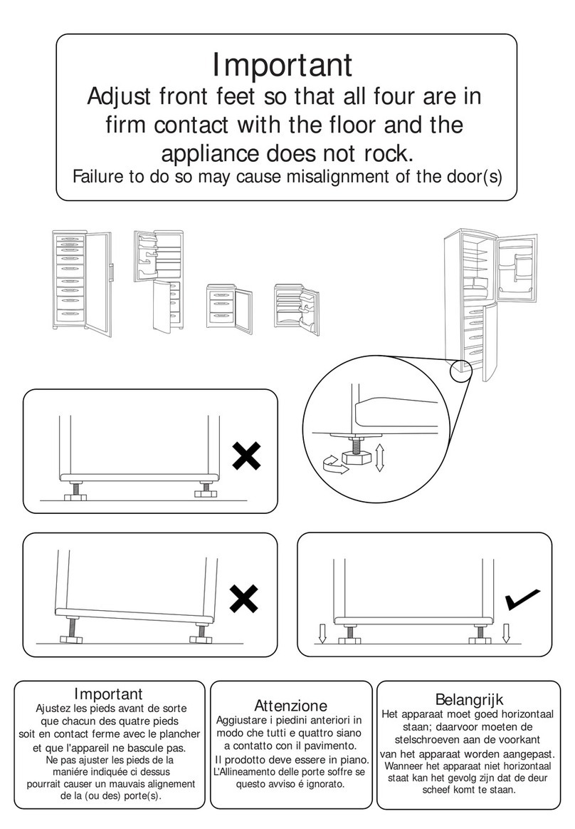
Adjust the feet to level the refrigerator.
Remove objects around it.
Slight sound similar
to that of flowing
water
Thid is the sound of the
refrigerating system
Normal
Heating of cabinet
The de-condensation system is
working refrigerating system.
This prevents condensation and is normal.
Table of contents
