pcl N72 User manual

76474 www.pclairtechnology.com
N72 Nitrogen Mobile Unit Generator User Manual
Safety Guidelines
This manual contains information that is very important to know
and understand. This information is provided for safety and to
prevent equipment problems. To help recognise this information,
observe the following symbols.
Danger indicates an imminently hazardous
situation which if not avoided WILL result
in death or serious injury.
Warning indicates a potentially hazardous
situation which if not avoided, COULD
result in death or serious injury.
Caution indicates a potentially minor or
moderate injury.
Notice indicates important information,
that if not followed, may cause damage to
equipment.
Unpacking
After unpacking the unit, inspect carefully for any damage that
may have occurred during transit.
Do not operate unit if damaged during
shipping, handling or use.
General Safety Information
The operator of this product must take the necessary precautions
to prevent the level of danger indicated by these symbols. The
operator is required to read and understand this instruction
manual and all safety warnings, labels etc.
Any employer allowing the use of this product in their field of work
must distribute this instruction manual to all users. The employer
must also ensure all users read, understand and follow the
instructions as described in the manual, safety warnings, labels,
etc.
Read and understand all safety warnings
and instructions before operating this
product. Failure to read and follow all
safety warnings may result in serious
personnel injury or death. Property
damage and/or product damage may also
occur if all warnings are not followed.
Please read and save these instructions. Read carefully before attempting to assemble, install, operate or maintain the product described.
Protect yourself and others by observing all safety information. Failure to comply with instructions could result in personal injury and/or
property damage! Retain instructions for future reference.
Purchased Nitrogen Cart may not be representative of the image shown
1. Do not expose the product to flammable gases,
vapours or fumes
2. Do not store flammable gases in or near this product
3. Never use flammable or toxic solvents to clean the
product or any of the unit's parts
4. Never remove or alter any safety warning labels, tags,
etc. located or provided with product.
5. Follow all directions for maintenance.
The use of other than genuine PCL
replacement parts may result in reduced
equipment performance. Repairs must be
performed by authorised repair personnel,
otherwise the warranty will be void.
PART NUMBER
SERIAL NUMBER

N72 Mobile Nitrogen Unit Generator User Manual
www.pclairtechnology.com
General Specifications
Guidelines
In order to provide a trouble free operation it is necessary to
connect the power supply from the main switchboard with a MAX
3amp fuse/RCB protection device.
The circuit breaker should be marked as the disconnecting device
for the equipment.
The compressor producing the air should have the necessary
water and dirt filtration, to minimise accumulation of debris at the
inflator line filter strainer. There must be no oil mist in the air inlet
line.
For efficient tyre inflation, ensure that the air supply is 14.5 psi, 1
bar or 100kpa above the intended maximum inflation range.
Inside installations
Use 3 pin connecting plugs or 2 pin + Earth with the Earth Ground
wire installed on electrical infrastructure.
The unit is designed to run with the earth connection installed.
"According to Class 1 - Basic insulation in conjunction with
protective Earthing"
Calibration & Accuracy
The accuracy of our digital units when released from our factory is
that:-
The maximum permissible error (MPE) = 0.08 bar
Each unit, before release, is checked and calibrated on test
equipment that has accuracy traceable to a UKAS Laboratory No.
0221 referenced to certificate 0029346.
Emergency Stop
Stop the inflation / deflation cycles by pressing any button on the
front panel or by turning the unit off.
Battery Charging
It will take 3 hours from flat to full battery storage.
Charger LED Status:
Orange—Fast Charge
Yellow—Top Off 90% Full
Green—Fully charged with trickle charge
Approximate hours from full charge of Continual Tyre Inflation and
Deflation = 24 hours.
Approximate hours of Continuous Machine Idle Time = 140 hours.
Do Not leave battery in an uncharged state as this will irreparably
damage the battery!
N72
Variant
Max Inlet
Supply
Recommended
Supply
Max
Pressure
Min Inflation
Pressure
Display
Resolution
Units of
Measurement
Electrical
Supply
N72 188.5psi/13bar/
1300kPa
14.5psi/1bar/100
kPa above cut off
pressure 116
psi/8 bar/800 kPa
102 psi/7
bar/ 700 kPa
4psi/0.3bar/
30kPa
1psi /0.1bar/
10kPa
psi/bar/kPa 90 V a.c. to 240 V a.c.
Battery Charger. Control
Head 12 V d.c.
Pre-use installation elements
Before unpacking of the unit please note the unit is screwed down
to the pallet. Remove 3 screws holding the unit to the pallet.
NOTE: the unit is heavy, 2 man lift required.
Ensure an outlet hose is connected to the output port.
The unit will need charging up before first use.
The unit is supplied with either:
UK power lead (as standard)
US power lead (customer specified variant) supplied with 120V US
plug.
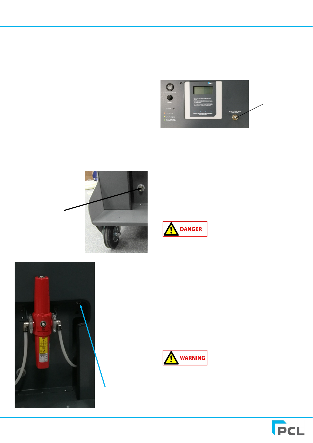
Battery Charger a.c. Input Port
Battery Charge
Indicator Dial
On-Off Switch
Battery Charge
Status LED
N72 Mobile Nitrogen Unit Generator User Manual
www.pclairtechnology.com
Air Inlet Port (Rp1/4
standard, 1/4 NPT on
request)
Outlet Port
System set-up instructions
1. Connect to air supply by screwing your chosen adaptor to the
Rp 1/4 fitting (1/4 NPT for US versions) into the compressed air
inlet port of the Filter Unit. Then connect your outlet hose to the
outlet port.
2. Connect the mains power lead to the C7 socket on the side of
the unit. The LED will change colour to ‘Green’ when the unit is
fully charged. This will take 3 hours from a flat battery.
Operation
1. Connect the output hose into customer pipework.
2. Turn the on-off switch to On, if the pressure in the system is
less then 8 bar the unit will start generating Nitrogen.
3. The unit will continue generating until a system pressure of 8
bar is achieved, the unit will stop until the pressure has dropped to
7 bar, and will restart, or the battery is exhausted, in which case it
will need recharging.
Nitrogen Purity Test Port
This is located on the top of the unit and is designed to identify the
purity of Nitrogen being produced by the machine. To identify the
purity of Nitrogen being produced ensure the unit is turned on
then remove the valve cap and push the connector on a PCL
Nitrogen Analyser unit (N2A001) which will automatically give you
a purity readout.
Nitrogen Purity
Test Point
Calibration & Accuracy
The accuracy of our digital units when released from our factory
is that:-
The maximum permissible error (MPE) = 0.08 bar.
Service / Maintenance
There is no requirement to service the following items:
1. Pressure Transducer
2. Electric Control Board
If these are faulty they can only be
replaced by a competent person.
Please refer to an Authorised
dealer.
Periodically
• Check the hoses.
• Check the tyre connector.
• Remove air input supply and tyre hose from the head.
• Check the Filter Indicator and replace filters if required.
Working safety instructions
Since the unit is not explosion-proof, the device should not be
installed in areas where explosions are possible. Consideration
must be given to the requirements relative to Hazardous Area
Standards for your region or country.
The unit is designed and built to the relevant basic health and
safety requirements of the EC.
This product can be dangerous if used
improperly. Children should not be
allowed to use this equipment, as
incorrect setting can allow tyre to be
over inflated and a subsequent tyre
burst/explosion can occur!
Each person who is involved with installation, start-up,
maintenance and the operation of the unit must read and
understand the complete operating manual.
N72 Mobile Nitrogen Unit Generator User Manual
www.pclairtechnology.com
The PCL tyre inflators are exclusively approved for the
dispensing of air/N2. Each use which doesn't follow this
purpose as well as modifications to the product will be
deemed to be improper use. The manufacturer is not liable
for damages caused by improper use, the risk lies solely
with the user.
Proper use of the product also implies the
observance of the manufacturers
instructions with regard to installation,
start-up, operation and maintenance.
All works concerning installation, start-up,
adjustment and maintenance must be
made by qualified staff. For the operation
of this tyre pressure inflator the local
safety and accident prevention rules must
be observed in all cases.
High Pressure air is stored within the
system.
Do not exceed the maximum air input
pressure.
Do not operate this product if tired or
under the influence of medication, drugs
or alcohol.
To avoid the risk of personal injury,
especially to the eyes, face or skin DO
NOT direct the air/N2 stream at any
person.
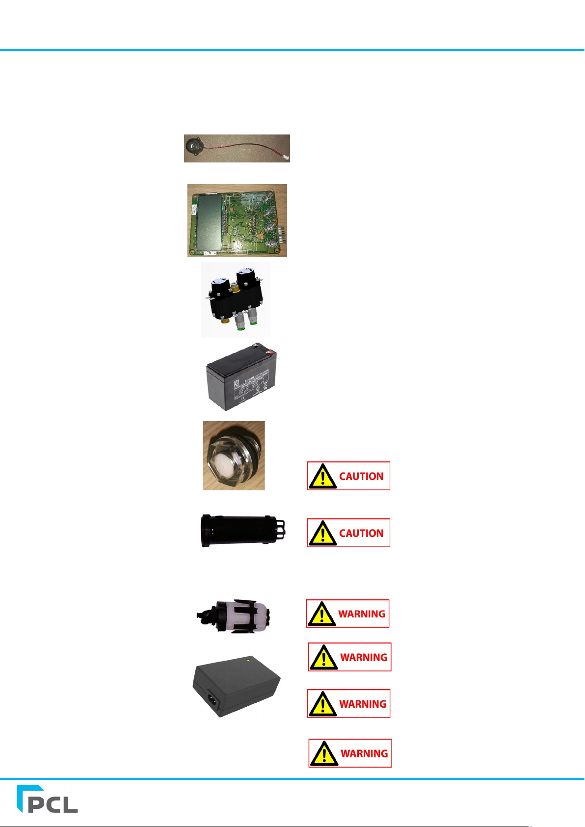
Available Spares
Part No. Description
DS40
Control Head
Buzzer
Control Head Main
Card PCBA
DS210
Air Inlet Solenoid
SPR4500
Battery 7 Ah,
12 V d.c.
N2S47
Filter Warning Plug
N2S43
Filter 1st Stage
N2S42
Filter 2nd Stage
SPR4400
Battery Charger
How to replace Battery Charger (Part No. SPR4400).
1. Remove Rear Cover.
2. Disconnect Battery leads.
3. Disconnect Battery Charger leads from quick clip connectors.
4. Remove 4 off M5 Nuts retaining battery charger cage.
5. Discard old charger noting local WEEE regulations.
6. Refitting is the reverse of the removal method. (Ensure the
charger is mounted the correct way round allowing the LED to
be seen through the control panel and the mains connector is
visible through the opening in the side of the unit).
How to replace Battery 7 Amp Hour, 12 V d.c., Lead Acid
(Part No. SPR4500).
1. Remove Rear Cover.
2. Disconnect Battery leads.
3. Remove 4 off M5 Nuts retaining battery cage.
4. Discard old battery noting local WEEE regulations.
5. Refitting is the reverse of the removal method. (Ensure the
battery is mounted the correct way round with the terminals
towards the side of the unit and the black and red wires are
connected to the correct terminals).
N72 Mobile Nitrogen Unit Generator User Manual
www.pclairtechnology.com
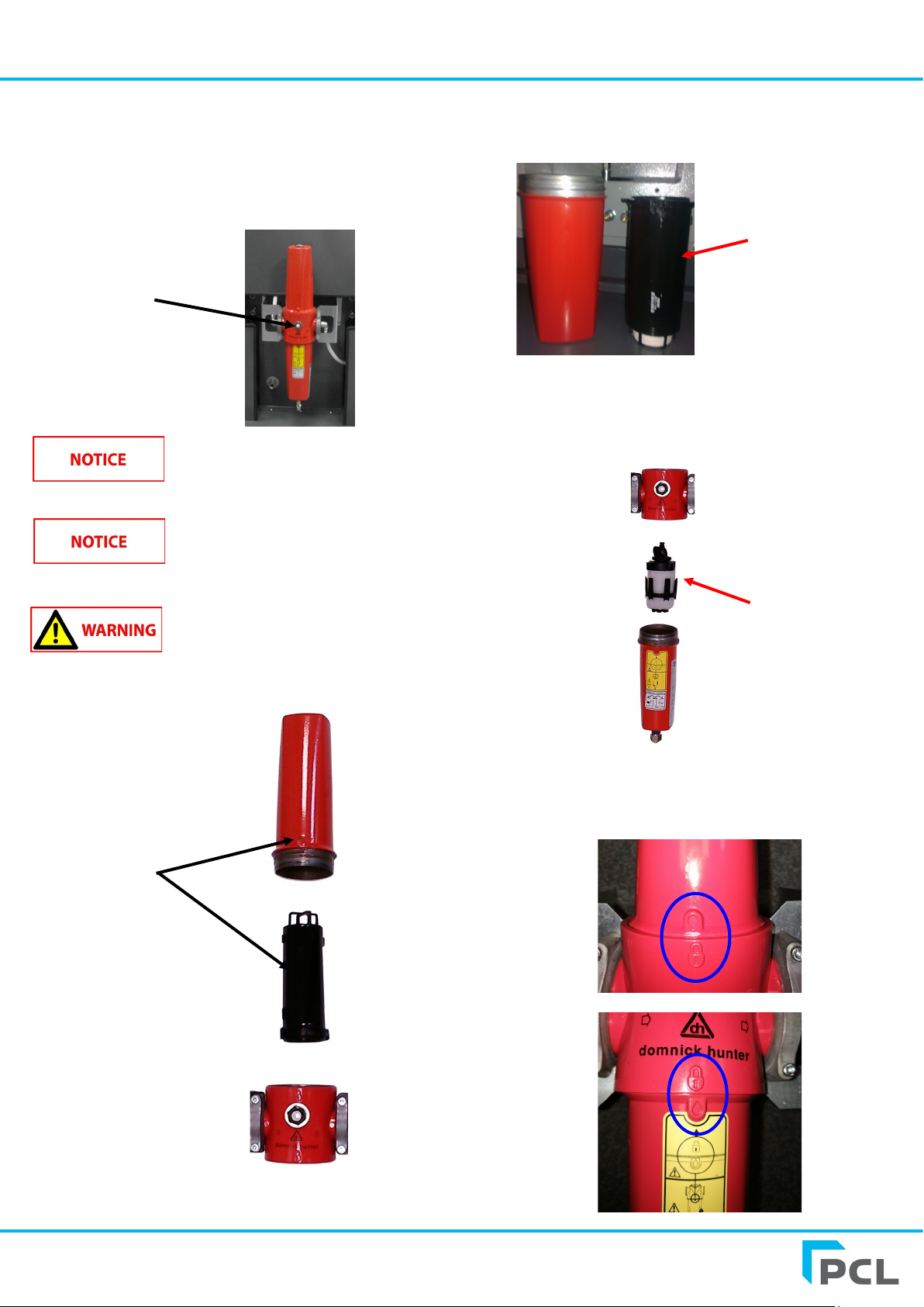
Instructions for changing the
filter elements on the integral
Domnick Hunter filters.
When the white indicator ‘spot’ on the front window inside the
unit turns blue the filter elements need replacing. The average
lifespan of the filter elements is 600 working hours.
If the filter elements are not replaced
when the indicator turns blue then the
membrane system is liable to be
damaged.
Depending on the amount of ozone and
moisture coming from the compressor
this lifespan can increase or decrease.
Ensure air connection to the generator
unit has been removed or shut off before
attempting to remove filter bowls.
1. Unscrew the top bowl by screwing the top half of the housing
anti-clockwise until the bowl can be removed.
Filter Change
Indicator
2. Inside the top half bowl should be the ozone filter which is
black in colour. This can simply be pulled out with a small
amount of pressure.
3. Replace this with a new filter (part number: N2S43)
4. Screw the top bowl back into position, ensuring the bowl has
clicked into place in the main housing.
5. Repeat the above process for the lower bowl, this contains
the secondary oil mist and moisture filter (part number:
N2S42).
6. When replacing the bowls you must ensure they are screwed
back in properly, with the two symbols aligning against the body
of the filter as seen in the images below.
Removed bowl
and internal
filter element
First stage filter
element (N2S43)
Second stage filter
element (N2S42)
N72 Mobile Nitrogen Unit Generator User Manual
www.pclairtechnology.com
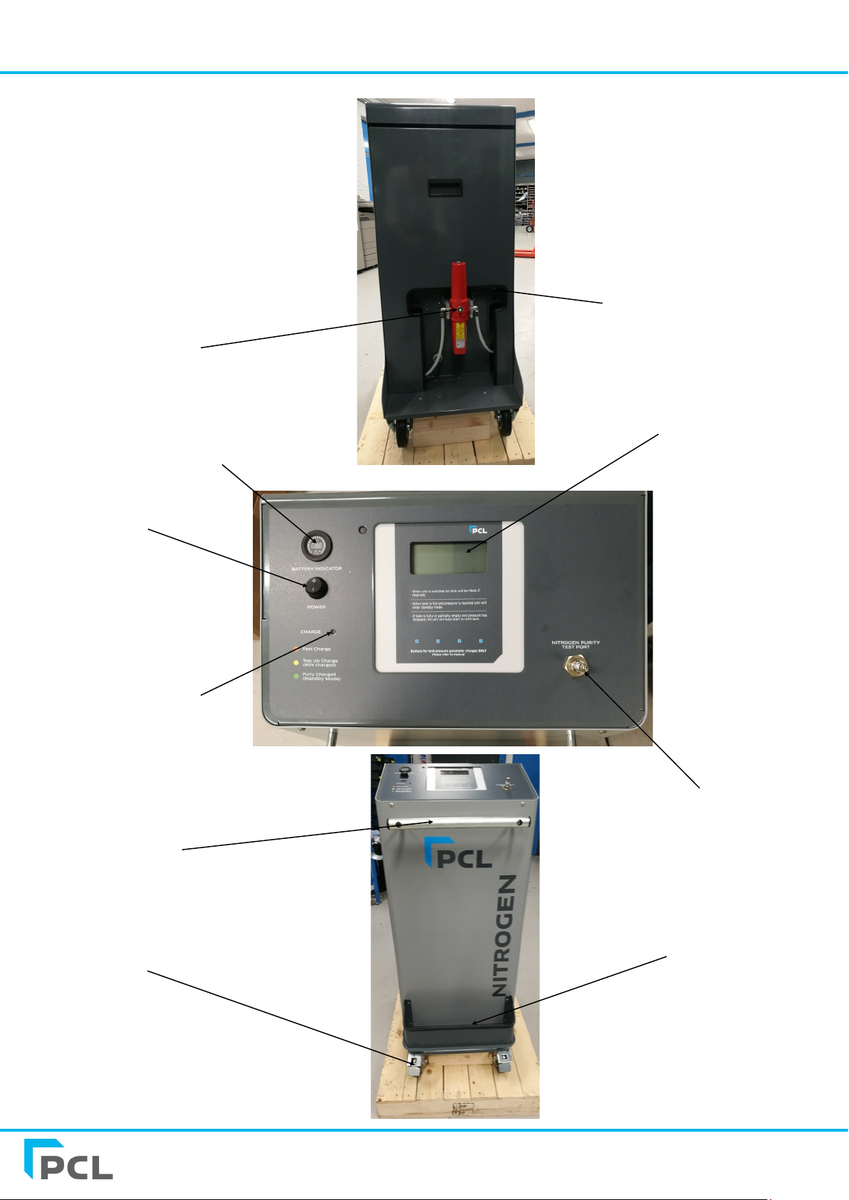
LCD Display
Charger Cable
Tray
Output Port
125mm castors
On/Off Switch
Nitrogen Purity Test Point
Handle
Unit view
Filter Indicator
Battery Voltage Indicator
Charge Status LED

N72 Mobile Nitrogen Unit Generator User Manual
www.pclairtechnology.com
Trouble Shooting Guide/Error Messages
Problem Possible Cause Solution
No display No power connected / Battery needs charging Switch power on / Charge Battery
No generation process System has reached 8 bar and shut off Wait for pressure to drop & unit will restart
Buzzer does not sound Buzzer volume has been turned off
Buzzer is damaged
Turn buzzer on
Replace buzzer
Generation process starts but
does not complete
Low or no supply pressure
Leaks exist
Check supply pressure
Confirm leaks do not exist
Inflating or deflating is very slow Check that mesh filters under input and output
port fittings are blocked
Clean and or replace mesh filters
E1 Unstable or insufficient supply pressure Check the supply pressure
E4 Small volume, caused inflator to check pressure
> 2bar / 29psi over target pressure
Check hose is not kinked or blocked, ensure a OPEN
END connector is installed
E5 Inflator started under pressure i.e. is connected
to tyre or a CLOSED END connector is being used
Remove hose from tyre and allow inflator to reset
Change connector to OPEN END type
E6 Pressure sensor drift out New sensor required - Refer to authorised repairer
E8 Pressure sensor disconnected from PCB or faulty New sensor required - Refer to authorised repairer
E9 Pressure sensor failure - high New sensor required - Refer to authorised repairer
E10 Under voltage Check power supply
E11 Over voltage Check power supply - Refer to authorised repairer
E12 Checksum corrupted New PCB required - Refer to authorised repairer
E13 Lost or corrupted calibration settings New PCB required - Refer to authorised repairer
E14 Count issue New PCB required - Refer to authorised repairer
E17 Calibration settings corrupt Recalibrate unit - Refer to authorised repairer
E18 Runtime error New PCB required - Refer to authorised repairer
E19 Touch screen error New PCB required - Refer to authorised repairer
E20 - E23 Start-up sequence error(s) New PCB required - Refer to authorised repairer
E24 Membrane count/run hours error New PCB required - Refer to authorised repairer
E25 N2 count/run hours error New PCB required - Refer to authorised repairer
E28 Signature mismatch / PCB error New PCB required - Refer to authorised repairer

PCL LIMITED WARRANTY
PCL warrants the components of each unit to which this Limited Warranty applies against defects in materials and workmanship for a period of twelve (12)
months from date of sale (as evidenced by bill of sale or equivalent) or for a period of eighteen (18) months from date of shipment from PCL manufacturing
facility (identifiable by the serial number and noted on original bill of lading from the manufacturing facility), whichever period is shorter. During this
warranty period and subject to the conditions set forth in this statement, PCL will, at its option, repair or replace component parts that were defective at the
time of shipment from PCL manufacturing facility, subject, however, to the following specific EXCLUSIONS: hoses and connections.
Repair or replacement will not extend the warranty period.
Customer must give PCL timely notice of any warranty claim by contacting an authorized PCL service centre. Claims must be accompanied by (1) evidence,
by a bill of sale or equivalent, which clearly establishes date of purchase of the unit and (2) the serial number, found on the unit. Customers must properly
pack parts in their original or equivalent packaging, prepay shipping charges, and insure the shipment or accept the risk for loss or damage in shipment.
Return shipment to customer will be freight collect unless otherwise agreed. For service at a customers location, customer will be charged the then
prevailing service rates .
The Limited Warranty applies to PCL manufactured units only. Items listed in the applicable operators manual under routine maintenance are not covered
by this or any other warranty. Failure to complete maintenance as stated in any applicable maintenance schedule will void the Limited Warranty. The
Limited Warranty is expressly conditioned upon proper and normal use and service of the unit and upon strict compliance by customer with all of PCL
instructions and recommendations for installation, operation and maintenance. The Limited Warranty does not apply to the unit or parts that are damaged
or become defective due to improper handling, maintenance, storage, use, or operation, and does not cover ordinary wear and tear, corrosion, or erosion.
THE LIMITED WARRANTY SET FORTH IN THIS STATEMENT CONSTITUTES PCL'S SOLE WARRANTY FOR THE UNIT AND THE REMEDIES SET
FORTH HEREIN CONSTITUTE CUSTOMERS SOLE REMEDIES FOR BREACH OF WARRANTY. THIS LIMITED WARRANTY IS IN LIEU OF ALL
OTHER WARRANTIES, EXPRESS OR IMPLIED, IN FACT OR BY LAW, INCLUDING WITHOUT LIMITING THE GENERALITY OF THE FOREGOING,
ANY WARRANTY OR MERCHANTABILITY OR FITNESS FOR A PARTICULAR PURPOSE.
Determination of the suitability of the unit for the use contemplated by the customer is the sole responsibility of the customer. PCL shall not, under any
circumstances, be liable in contract, tort or otherwise (including negligence and strict liability) for indirect, special, incidental, or consequential damages,
and PCL's total liability shall not exceed the net purchase price for the unit. PCL shall be excused for delay or inability to perform obligations due to events
beyond its reasonable control.
Test Certificate
Each unit, before release, is checked and calibrated on test equipment that has accuracy
traceable to Druck pressure indicator S/N2329290.
The Druck unit is referenced to Certificate 0029346 issued by UKAS Laboratory No. 0221.
This accuracy exceeds and BS EN 12645:2014 (MPE = 0.08 bar).
PART NUMBER
SERIAL NUMBER
SET PURITY (%)
TESTED BY
DATE
Declaration of conformity
• Note : The declaration of conformity is valid for units operating at 230V/50Hz.
• 2014/30/EU (EMC directive) confirmed by report No. TRA-034746-36-02A
• 2014/35/EU (LOW Voltage Directive).
• National regulations EN12645 : 2014, French National Approval LNE-3345—Rev 0, report no. LNE-33471—Rev 0 and
Portugal Approval (IPQ) report no. 245.30.17.3.18
Mark McCaughey
Technical Director on behalf of PCL
Other manuals for N72
1
Table of contents
Popular Inverter manuals by other brands


Sunways
Sunways AT 5000 user manual

Honeywell
Honeywell HW1000i - Portable Inverter Generator specification

Olimpia splendid
Olimpia splendid PHENIX E Instructions for use and maintenance

Danfoss
Danfoss VLT 2800 Series quick start guide

Olimpia splendid
Olimpia splendid DUAL INVERTER 14 Instructions for use and maintenance

SEW-Eurodrive
SEW-Eurodrive MOVIDRIVE DFC11A manual


