manuals.online logo
Brands
  1. Home
  2. •
  3. Brands
  4. •
  5. Growatt
  6. •
  7. Inverter
  8. •
  9. Growatt SYN 50-XH-1 User manual

Growatt SYN 50-XH-1 User manual

1.
2.
SYN 50-XH-1 Quick Guide
Overview
Installation
System overview 2.1 Installation requirements
2.2 Installation steps
1:Front panel
2:LED indicator
3:Screw for top cover
4:The main frame body
5:Mounting bracket
6:COM wiring port
7:Generator wiring port
8:Grid wiring port
9:Inverter wiring port
10:Load wiring port
11:Waterproof plugs
No.
Name
Size
No.
Name
Size
1
straight
screwdriver
Φ5mm
2
hammer
/
3
Allen wrench
Φ5mm
4
Cross rise
Φ5mm
5
Electric drill
Φ6mm
6
Wire stripper
/
7
Line pressing
pliers
/
2.3 Required tools
3.2 Wiring instructions
1.Take out the two screws on the upper cover of the machine, open the upper cover, and do not
remove the ugly plate inside the machine.
2.Loosen the plastic cover printed as " Grid " counterclockwise, remove the three waterproof plugs,
and reserve three holes.
3.Route the three power grid cables (L/N/PE) through the three holes and connect them to the power
grid input terminal and the ground copper bar. The screw torque on the power grid terminal is 26.5
in*lbs / 3.0 N*m to 31 in*lbs / 3.5 N*m, and the screw torque on the ground terminal is 13 in*lbs / 1.5
N*m.
4.Finally, fasten the plastic cover clockwise. Wiring is shown as follows:
Grid
DC
AC
PV
AC
AC
AC
DC
Generator
Battery
Inverter
Load
The front, back and side pictures of the machine are as follows:
1.Determine SYN 50-XH-1 mounting location, on a wall, stud framing or pole. It is recommended to mount the Backup Interface in a location
protected from direct sunlight.
2.To allow proper heat dissipation, maintain at least a 300mm clearance between the SYN 50-XH-1 and other objects.
3.Position the mounting bracket against the wall/pole and mark the drilling hole locations.
4.Drill the holes and mount the bracket. Verify that the bracket is firmly attached to the mounting surface.
5. Hang SYN 50-XH-1 on the bracket.
1 2 3 4 5 6
≥300mm≥300mm
≥300mm
≥300mm
≥500mm
3.
Wire specification suggestions
The cable specifications of this machine are as follows, and the wiring end is stripped 10mm.
project
Wire diameter
Line length
Grid input cable
6-8AWG
10m
Inverter input cable
8-12AWG
20m
Load output cable
8-12AWG
20m
Generator input cable
6-8AWG
10m
Communication cable
22-26AWG
20m
6-8AWG
10m
L
10mm
10m
6-8AWG
6-8AWG
N
10mm
10m
PE
10mm
Grid and Generator AC cable
20m
10-12AWG L
10mm
20m
10-12AWG
10-12AWG
N
10mm
20m
PE
10mm
Load and lnverter AC cable
20m
20m
24-26AWG
24-26AWG
L
10mm
N
10mm
Communication cable
3.2.1 Connecting SYN 50-XH-1 to the Grid
3.2.2 Connecting SYN 50-XH-1 to the Inverter
When connecting theSYN 50-XH-1 to the XH Inverter, we need to connect AC power cable and communication cable.
1.Loosen the plastic cover printed as "Inverter" counterclockwise, remove the three waterproof plugs, and reserve three holes.
2.Route the cables of the three inverters (L/N/PE) through the three holes, connect the cables to the inverter circuit breaker terminal and the
ground copper bar. The screw torque of the inverter circuit breaker terminal is 17.5 in*lbs / 2 N*m, and the screw torque on the ground
terminal is 13 in*lbs / 1.5 N*m.
3.Finally, fasten the plastic cover clockwise. Wiring is shown as follows:
21 354 678910
11
11
≤15°
≥300mm
365
92.5
490.3
134.7
120.2
7
Grid
Grid
LN
PE L
PE N
Connection to the Grid
PE
1
2
1)To connect to the AC cable:
1
3
1.Loosen the plastic cover printed as "Load" counterclockwise,
remove the three waterproof plugs, and reserve three holes.
2. Route the three load cables (L/N/PE) through the three holes,
connect them to the load circuit breaker terminal and ground copper
bar. The load breaker terminal screw torque is 17.5 in*lbs / 2 N*m, and
the ground terminal screw torque is 13 in*lbs / 1.5N*m.
3.Finally, fasten the plastic cover clockwise. The wiring is shown on
the right:
5. System startup and shutdown operations
5.1 To start the system, please follow the following steps:
5.2 Shut down the system, please refer to the following steps:
GR-UM-256-A-00
Download
Manual Growatt New Energy
Shenzhen Growatt New Energy CO.,LTD
4-13/F,Building A,Sino-German(Europe) Industrial Park,
Hangcheng Ave, Bao’an District, Shenzhen, China
+86 0755 2747 1942
www.ginverter.com
T
E service@ginverter.com
W
7.
Service and contact
When connecting the SYN 50-XH-1 to the Generator, we need to connect AC power cable and the dry signal cable.
1.Loosen the plastic cover printed as "Generator" counterclockwise, remove the three waterproof plugs, and reserve three holes.
2.Route the three generator cables (L/N/PE) through the three holes, connect them to the generator circuit breaker terminal and ground
copper bar. The screw torque of the generator circuit breaker terminal is 17.5 in*lbs / 2 N*m, and the screw torque on the ground terminal is
13 in*lbs / 1.5 N*m.
3.Finally, fasten the plastic cover clockwise. Wiring is shown as follows:
1.Route the two communication cables (DRY+/DRY-) through the COM hole and connect them to the CN6 terminal on the control board.
The other end of the communication cable is connected to the signal control point of the generator.
2.Fasten the plastic cover with "COM" clockwise.
3. Finally, close the upper cover of the machine and lock it with screws, torque 31 in* lbs / 3.5 N*m. Connection mode is as follows:
1.Turn on the DC switch of the ARK battery. For details, Please refer to the ARK battery manual.
2.Turn on the DC switch of the inverter. For details, Please refer to the XH inverter manual.
3.Turn on the power grid switch, then turn on the inverter input breaker of the SYN 50-XH-1, and observe whether the inverter and
battery indicators are displayed. If yes, go to the next step. If there is no display, it means that there is no mains supply. You need to
press the POWER button of the ARK battery for a long time to wake up the battery. Please refer to the ARK battery installation manual.
4.Through the upper computer of the inverter, turn on the inverter off-grid enabling function and set register 225 to 1. For detailed
operations, please refer to the inverter user manual.
5.After the preceding steps, if the indicator of the SYN 50-XH-1 is green, it indicates that the SYN 50-XH-1 is working properly.
1.Disconnect the Inverter input breaker on the SYN 50-XH-1 and then disconnect the power grid switch.
2.Turn off the DC switch of the inverter.
3.Turn off the DC switch of the ARK battery.
4.Waiting for a while, and then all the indicators of the inverter, the ARK battery, and the SYN 50-XH-1 went out. The system is powered
off completely.
Connection to the AC Loads
4. LED Description
System state
LED state
Green
Red
On-grid Mode
On
Off
Back-up Mode
Blinking,on 1s,off 1s
Off
No communication with the inverter
Off
Blinking,on 1s,off 1s
System fault
Off
On
Firmware upgrade
The yellow light blinks, on and off for one second
3.2.3 Connecting SYN 50-XH-1 to the load
3.2.4 Connecting SYN 50-XH-1 to the Generator (optional)
ON
OFF
Inverter
L N
COM Port
XH Inverter SYS COM
SYN 50-XH-1 CN8
RS485 A
PIN 5
A
RS485 B
PIN 6
B
1.Loosen the plastic cover printed as "COM" on the machine counterclockwise, remove the waterproof plug, and reserve a hole.
2.Route the two communication cables of (A/B) through the hole, connect them to the CN8 terminal of the control board, connect the other
end of the cable to the SYS COM terminal of the inverter, and tighten the screws. The following table lists the corresponding terminal pins.
Wiring is shown as follows:
PE
NLPE
SYS COM
COM
CN8
B
A
1
6
Connection communication cable to the XH Inverter
12
Backup Loads
ON
OFF
LNN LL PE
PE
Connection AC cable to the Generator
ON
OFF
PE N L L N
PE
Generator
Connect the dry signal of the generator diagram
GEN
COM
CN6
COM
NO
6.
Manual bypass operation
When SYN 50-XH-1 fails, it cannot be switched to the bypass state. In order to ensure that the household power supply can be manually
switched to the mains bypass state
1.Shut down the entire system. For details, please refer to section 5.2.
2.Manually turn off the inverter switch and load switch (“OFF” indicates turn off state).
3.Use a Phillips screwdriver to loosen the firmware screws on the power bypass switch.
4.Slide the firmware to one end of the inverter switch.
5.Tighten the screws on the firmware, Turn on the power bypass switch (“ON” indicates turn on state). The torque of the screws is 10.5
in*lbs / 1.2 N*m. The operation is shown below.
6.Power on the entire system. For details, please refer to section 5.1.
Bypass Inverter Load Bypass Inverter Load Bypass Inverter Load
The operation is as follows:
2)To connect to the communication cable:
1)Connecting the AC cable:
2)Connecting the dry signal cable:
1 2
1 2
Load
Connection AC cable to the XH Inverter
“ON”state “OFF”state

Other Growatt Inverter manuals

Growatt 2500MTL User manual

Growatt

Growatt 2500MTL User manual

Growatt MIN 6000 TL-XH User manual

Growatt

Growatt MIN 6000 TL-XH User manual

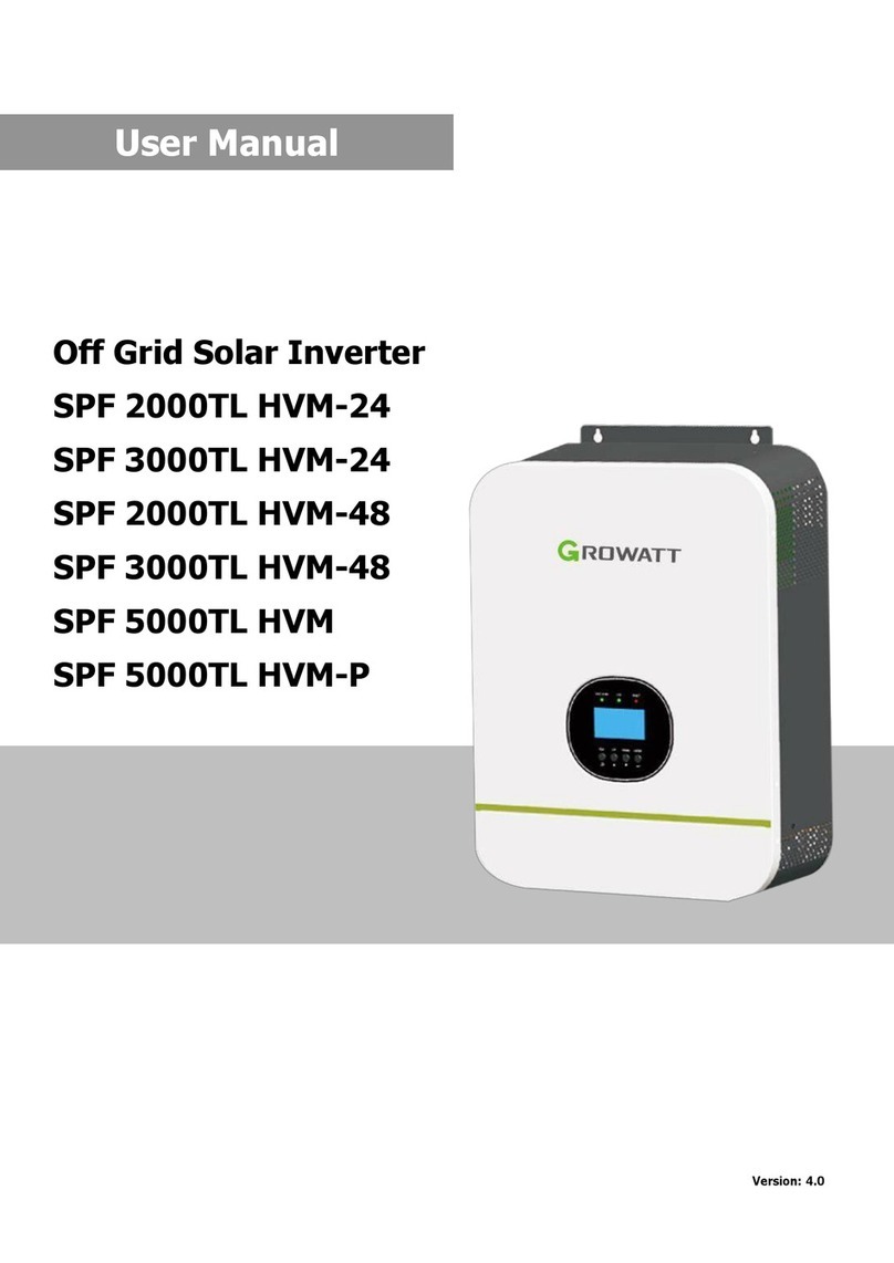
Growatt SPF 5000TL HVM User manual

Growatt

Growatt SPF 5000TL HVM User manual

Growatt MIN 3 K-11.4K TL-XH-US User manual

Growatt

Growatt MIN 3 K-11.4K TL-XH-US User manual

Growatt MOD 3-15KTL3-X User manual

Growatt

Growatt MOD 3-15KTL3-X User manual

Growatt MAX 175KTL3-X HV User manual

Growatt

Growatt MAX 175KTL3-X HV User manual

Growatt MIN 3000TL-XH-US User manual

Growatt

Growatt MIN 3000TL-XH-US User manual

Growatt 30000 TL3 User manual

Growatt

Growatt 30000 TL3 User manual

Growatt MID 1 7 KTL3-X1 User manual

Growatt

Growatt MID 1 7 KTL3-X1 User manual

Growatt MIN 7000TL-X User manual

Growatt

Growatt MIN 7000TL-X User manual

Growatt SPA TL3 BH-UP Series User manual

Growatt

Growatt SPA TL3 BH-UP Series User manual

Growatt Shine WebBox User manual

Growatt

Growatt Shine WebBox User manual

Growatt SPF 5000 ES User manual

Growatt

Growatt SPF 5000 ES User manual

Growatt 750-S User manual

Growatt

Growatt 750-S User manual

Growatt CP250 User manual

Growatt

Growatt CP250 User manual

Growatt SPH Series User manual

Growatt

Growatt SPH Series User manual

Growatt MIN 2500TL-XA User manual

Growatt

Growatt MIN 2500TL-XA User manual

Growatt 3-10KTL3-XH User manual

Growatt

Growatt 3-10KTL3-XH User manual

Growatt SPF 3000TL LVM User manual

Growatt

Growatt SPF 3000TL LVM User manual

Growatt 7000MTL-S User manual

Growatt

Growatt 7000MTL-S User manual

Growatt SPF 4KT HVM User manual

Growatt

Growatt SPF 4KT HVM User manual

Growatt PCS500 User manual

Growatt

Growatt PCS500 User manual

Growatt SPF 6000 ES PLUS User manual

Growatt

Growatt SPF 6000 ES PLUS User manual

Growatt Grid User manual

Growatt

Growatt Grid User manual

Popular Inverter manuals by other brands

ABB UNO-DM-TL-PLUS-US product manual

ABB

ABB UNO-DM-TL-PLUS-US product manual

INVT Goodrive 200 Operation manual

INVT

INVT Goodrive 200 Operation manual

SolaX Power T-BAT H 11.5 manual

SolaX Power

SolaX Power T-BAT H 11.5 manual

TECO F33 Series instruction manual

TECO

TECO F33 Series instruction manual

Wagan Smart AC 100W USB user manual

Wagan

Wagan Smart AC 100W USB user manual

Goodwe ES Series user manual

Goodwe

Goodwe ES Series user manual

SMA SUNNY BOY 5000TL user manual

SMA

SMA SUNNY BOY 5000TL user manual

Sungrow SG60KTL Quick installation quide

Sungrow

Sungrow SG60KTL Quick installation quide

ESC PGEN-30 manual

ESC

ESC PGEN-30 manual

Deye SUN-29.9K-SG01HP3-EU-BM3 user manual

Deye

Deye SUN-29.9K-SG01HP3-EU-BM3 user manual

PCENERSYS M16S Series user manual

PCENERSYS

PCENERSYS M16S Series user manual

Power One AURORA PVI-STRINGCOMB Installation and instruction manual

Power One

Power One AURORA PVI-STRINGCOMB Installation and instruction manual

Cobra IG20SI user manual

Cobra

Cobra IG20SI user manual

Platinum 2100 H Installation and user guide

Platinum

Platinum 2100 H Installation and user guide

Advanced Energy Paramount MF 2 kW user manual

Advanced Energy

Advanced Energy Paramount MF 2 kW user manual

Hantek DDS-3X25 user guide

Hantek

Hantek DDS-3X25 user guide

DWT WACS PWM 201 manual

DWT

DWT WACS PWM 201 manual

SMA FLX Series installation guide

SMA

SMA FLX Series installation guide

manuals.online logo
manuals.online logoBrands
  • About & Mission
  • Contact us
  • Privacy Policy
  • Terms and Conditions

Copyright 2025 Manuals.Online. All Rights Reserved.