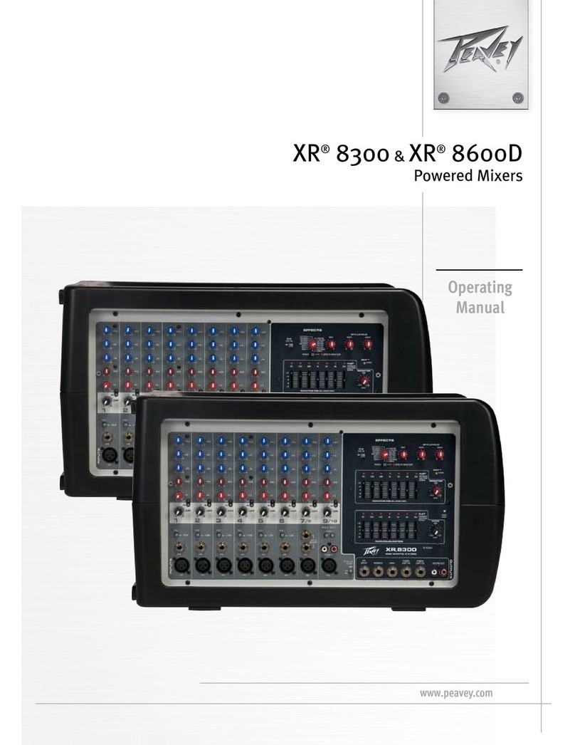
Peavey XR 684 User manual

®
OWNER’SMANUAL
XR®684
Stereo Powered Mixer

2
Intended to alert the user to the presence of uninsulated “dangerous voltage” within the product’s
enclosure that may be of sufficient magnitude to constitute a risk of electric shock to persons.
Intended to alert the user of the presence of important operating and maintenance (servicing)
instructions in the literature accompanying the product.
CAUTION: isk of electrical shock — DO NOT OPEN!
CAUTION: To reduce the risk of electric shock, do not remove cover. No user serviceable parts inside. efer
servicing to qualified service personnel.
WARNING: To prevent electrical shock or fire hazard, do not expose this appliance to rain or moisture. Before
using this appliance, read the operating guide for further warnings.
Este símbolo tiene el propósito, de alertar al usuario de la presencia de “(voltaje) peligroso” que no tiene
aislamiento dentro de la caja del producto que puede tener una magnitud suficiente como para constituir
riesgo de corrientazo.
Este símbolo tiene el propósito de alertar al usario de la presencia de instruccones importantes sobre la
operación y mantenimiento en la literatura que viene con el producto.
PRECAUCION: iesgo de corrientazo — No abra.
PRECAUCION: Para disminuír el riesgo de corrientazo, no abra la cubierta. No hay piezas adentro que el usario
pueda reparar. Deje todo mantenimiento a los técnicos calificados.
ADVERTENCIA: Para evitar corrientazos o peligro de incendio, no deje expuesto a la lluvia o humedad este
aparato Antes de usar este aparato, Iea más advertencias en la guía de operación.
Ce symbole est utilisé pur indiquer à l’utilisateur la présence à l’intérieur de ce produit de tension non-
isolée dangereuse pouvant être d’intensité suffisante pour constituer un risque de choc électrique.
Ce symbole est utilisé pour indiquer à l’utilisateur qu’il ou qu’elle trouvera d’importantes instructions sur
l’utilisation et l’entretien (service) de l’appareil dans la littérature accompagnant le produit.
ATTENTION: isques de choc électrique — NE PAS OUV I !
ATTENTION: Afin de réduire le risque de choc électrique, ne pas enlever le couvercle. Il ne se trouve à l’intérieur
aucune pièce pouvant être reparée par l’utilisateur. Confier I’entretien à un personnel qualifié.
AVERTISSEMENT: Afin de prévenir les risques de décharge électrique ou de feu, n’exposez pas cet appareil à la
pluie ou à l’humidité. Avant d’utiliser cet appareil, lisez les avertissements supplémentaires situés dans le guide.
Dieses Symbol soll den Anwender vor unisolierten gefährlichen Spannungen innerhalb des Gehäuses
warnen, die von Ausreichender Stärke sind, um einen elektrischen Schlag verursachen zu können.
Dieses Symbol soll den Benutzer auf wichtige Instruktionen in der Bedienungsanleitung aufmerksam
machen, die Handhabung und Wartung des Produkts betreffen.
VORSICHT: isiko — Elektrischer Schlag! Nicht öffnen!
VORSICHT: Um das isiko eines elektrischen Schlages zu vermeiden, nicht die Abdeckung enfernen. Es befinden
sich keine Teile darin, die vom Anwender repariert werden könnten. eparaturen nur von qualifiziertem
Fachpersonal durchführen lassen.
ACHTUNG: Um einen elektrischen Schlag oder Feuergefahr zu vermeiden, sollte dieses Gerät nicht dem egen
oder Feuchtigkeit ausgesetzt werden. Vor Inbetriebnahme unbedingt die Bedienungsanleitung lesen.

XR™684 Powered Sound Re nforcement M x ng Console
Compiled By: Peter Ochello, Technical Writer, Peavey Electronics Corp.
General Descr pt on:
Congratulations on your purchase of the X ™684 powered mixer. Within one compact unit, we
have packed feature after feature, each displaying the latest technology available. Here are several
features you will certainly want to notice:
• 8 low-noise, low-Z mic preamps
• 4 true high-Z 1/4" mic inputs
• 3-band equalization (Channels 1-8)
• Monitor send (each channel)
• EFX send (Channels 1-8)
• -25 dB pad (Channels 1-6)
• Low-cut filter (Channels 1-6)
• Stereo line inputs (Channels 7-9)
• 16-bit, DSP-based stereo reverb/effects with two parameter controls
• Two 9-band graphic EQs with FLS®Feedback Locating System®
• 48 V phantom power
• Stereo/Main-Monitor mode switch
• 2x200 W @ 4 ohms internal power amplifier
• 420 W @ 8 ohms in bridge mode
• DDT™speaker protection
The standard channels (1-4) feature discrete low noise mic preamps with globally switched
phantom power, true high-impedance 1/4" mic inputs, low-cut filters, and three-band EQs. Two
additional channels (5-6) offer balanced XL mic inputs and 1/4" line level inputs. Finally, there are
three stereo channels (7-9) for tape, CD, or synth inputs.
The master section features a unique graphic equalizer/power amp mode switch. Without patching,
the X 684 can be used as a full stereo mixer amplifier (default). In the Main/Monitor mode, one
graphic and amplifier can be used for monitor and the other graphic and amplifier for the main L &
(mono) signal.
Also included in the master section are 16 stereo digital effects from the award winning Deltafex™
digital signal processor. By including separate Time/Size and Color/Tone controls, the user can
create many effect settings from the 16 we provided. All channels, except Channel 9, have a dedi-
cated digital effects send routed directly to the DSP effects processor.
To take advantage of the X 684’s powerful features, please read this owner’s manual carefully
and keep it as a reference. This manual includes several sections detailing individual areas of mixer
operation, including: control functions, set-up, and applications in sound reinforcement.
3
ENGLISH

CHANNEL SECTION:
CHANNELS 1-4
1. MIC INPUT: XL balanced, low-impedance channel input optimized for a
microphone or other low-level source. Pin 2 is the positive input. Because of the
wide range of gain adjustment, signal levels as high as +10 dBV (2.45 V MS)
can be accommodated. When the phantom power is enabled, this connector
has +48 V on pins 2 and 3 with pin 1 as the ground reference. (The Mic Input
can also be found on channels 5 through 8.)
2. HI-Z/LINE INPUT: 1/4" balanced T S high-impedance input. The tip is the
positive input, which can also be used for unbalanced inputs. A Pad (#3) switch
is provided to attenuate strong signals present at this input. Within the same
channel, the mic input and the Hi-Z/Line input cannot be used simultaneously.
3. PAD: Attenuates the input signal by 25 dB. If you find that barely touching
the Level control (#4) gives you an enormous increase in volume or if distortion
occurs, try using the Pad switch. In addition to increasing the dynamic range,
the channel input can now accommodate a higher input level before clipping.
This may be necessary with a close mic on loud guitar amplifiers or drum kits.
(The Pad switch can also be found on channels 5 and 6).
4. LEVEL: Sets the signal level sent to the Left and ight bus. (The level
control can also be found on channels 5 through 9.)
5. MON: Adjusts the level of the channel signal (pre-EQ) that is added to the
Monitor mix. (The Monitor control can also be found on channels 5 through 9.)
This control is independent of the main channel level control (#4).
6. LOW EQ: A shelving type of active tone control that varies the bass
frequency levels ±15 dB at 70 Hz. It will add depth to thin signals, or clean up
muddy ones. (The low control can also be found on channels 5 through 9.)
7. MID EQ: Mid ±15 dB. This control sets the amount of cut and boost at the
mid-frequency. (The mid control can also be found on channels 5 through 8.)
8. HIGH EQ: A shelving type of active tone control that varies the treble
frequency levels ±15 dB at 12 kHz. It is designed to remove noise or to add bril-
liance to the signal, depending on the quality of the source. (The high control
can also be found on channels 5 through 9.)
9. EFX: This control varies the level into the digital effects processor bus
adjusting the signal level from the particular channel to the digital processor.
(The effects control can also be found on channels 5 through 8.) The channel
level control (#4) also affects this level.
1
4
5
6
7
8
9
2
3
4

NOTE: Channels 5-9 contain features that differ from the previous channels.
Only those features are mentioned below. For information on features not
mentioned please refer to the section for Channels 1-4.
CHANNELS 5-6
10. LINE: 1/4" balanced T S input for line level signals. This signal is connected
through a 25 dB pad to the mic input below it.
11. LOW CUT: This is a low-cut filter with a corner frequency of 80 Hz used to
filter rumble, wind noise, breath thumps, stage noise, and other low-frequency
components that rob power from the amplifiers and muddy the signal. Depressing
this switch will affect channels 1-6 only. Use of the filter will not affect the Monitor
signal.
CHANNELS 7-8
12. RIGHT INPUT: High-impedance 1/4" input for line-level signals. The ight
Input is adjusted by the Level control (#4). The signal is then routed to the internal
power amp. If the X 684 is in Left/ ight mode then the signal will go to the ight
Speaker Output (#37). In Mon/Main mode the signal is combined with the Left
and placed on the Main Speaker Output. The right signal can also be patched out
of the X 684 via the ight Output jack (#31) to external components such as
effects, power amps, and recording devices.
13. LEFT/MONO INPUT: High-impedance 1/4" input for line-level signals. The
Left/Mono input supplies signal to both the Left and ight channels (if there is
nothing inserted to the right input jack) through the Level control (#4). In
Left/ ight mode the signal will go to the Left Speaker Output (and ight Speaker
Output if nothing is inserted to the right input jack). In Mon/Main mode the signal
is combined with the ight and placed on the Main Speaker Output.
CHANNEL 9
14. TAPE IN: This stereo CA phono jack accepts a stereo input (nominally
-10 dBV) from the output of a tape deck or CD player and places it on the Left
and ight channels as well as the Monitor Mix.
15. TAPE OUT: This stereo CA phono jack provides a signal for the recording
inputs of a stereo tape deck.
CAUTION: DO NOT HOOK THE TAPE IN AND TAPE OUT TO THE INPUT AND
OUTPUT OF THE SAME DECK. DOING SO WILL FO M A LOOP
CAUSING SEVE E FEEDBACK. USE SEPE ATE DECKS FO
ECO DING AND PLAYBACK.
MASTER SECTION:
16. EFFECTS PEAK LED: Illuminates to indicate -6 dB of headroom before the
signals being sent to the effects circuit are clipped. Ideally, you would want this
LED to light only occassionally if at all. An occassional blink indicates that you
have the levels at an optimum setting. It is advisable to listen carefully to the
output at the same time in order to determine the final setting.
5
13
11
12
10
14
15

17. PRESET: Selects the effect preset from the list below.
EFX Presets
PRESET NAME TIME/SIZE COLOR/TONE
1 Chamber Time: 150 to 5,000 ms Damping (High Frequency)
2 Plate Time: 100 to 4,000 ms Damping (High Frequency)
3 oom Time: 150 to 5,000 ms Damping (High Frequency)
4 Cathedral Time: 100 to 8,000 ms Damping (High Frequency)
5 Spring Time: 150 to 5,000 ms Damping (High Frequency)
6 Gate Time: 150 to 500 ms Damping (High Frequency)
7 everse Time: 150 to 500 ms Damping (High Frequency)
8 Delay + everb Time: 0 to 225 ms everb Time: 0 to 5,000 ms
9 Bright Delay Time: 0 to 500 ms Feedback: 0 to 99%
10 Warm Delay Time: 0 to 500 ms Feedback: 0 to 99%
11 Dark Delay Time: 0 to 500 ms Feedback: 0 to 99%
12 Ping Pong Delay Time: 0 to 500 ms Feedback: 0 to 99%
13 Chorus ate: 0.125 to 8 Hz Depth: Best Set Full CW
14 Phaser ate: 0.250 to 16 Hz Depth: Best Set Full CW
15 Flange ate: 0.10 to 2.5 Hz Depth: Best Set Full CW
16 otary Speaker High Speed: 0.50 to 25 Hz Width: 0 to 100% CW
18. TIME/SIZE: In everb and Delay presets, this control adjusts the time of the particular reverb or delay;
in Chorus, Phaser, and Flange, it adjusts the rate of each. In otary Speaker setting, this adjusts the speed
of the speaker rotation.
19. COLOR/TONE: Adjusts the high-frequency content of the effects signal. (While using a delay this
control adjusts the feedback or depth.)
20. EFX TO MON: Controls the amount of effects signal sent to the monitor mix. This control allows effects
to be heard from the stage via the monitor.
21. EFX TO MAIN: Controls the amount of effects signal sent to the main mix.
22. FLS®(Feedback Locator System®): These LEDs illuminate to indicate the frequency band of highest
energy. When feedback occurs, this system will automatically indicate the graphics slider to use to decrease
that frequency band’s gain in order to lessen or eliminate feedback. (NOTE: These LEDs illuminate with any
audio signal, not just during feedback.)
23. GRAPHIC EQUALIZERS: These nine-band equalizers are fixed on one-octave centers. They are
designed for 12 dB of cut and 12 dB boost. They are connected directly to their power amplifier inputs.
24. SYSTEM MODE: This switch is used to configure the X 684 as either a stereo or dual mono amplifier.
It is recessed to prevent accidental switching during a performance. Use a non-metallic object to change the
switch position (e.g., a toothpick). The X 684 is shipped from the factory in the default setting of Left Main to
the upper EQ and ight to the lower EQ. When this switch is depressed it switches the lower EQ to (mono)
PA Left + ight. The upper EQ then becomes the monitor signal only, creating an entire PA and monitor mix-
ing system in one small, easy-to-carry package. And this change is accomplished without a single patch cord!
25. MONITOR LEVEL: Sets the overall level of the monitor signal that is sent to the Monitor Output Jack.
This control also sets the monitor level going to the power amp when in Main/Monitor mode (see System
Mode #24).
6

26. MAIN LEVEL: This is the master level control for the main mix sent to the Left/Mono and ight output
jacks. This control sets the Main level going to the power amp when in Main/Monitor mode (see System
Mode #24). A good starting position for this control is the center detent position (12:00).
27. PHANTOM POWER SWITCH: Applies 48 V DC voltage to all input XL connectors to power micro-
phones that require it.
CAUTION! When phantom power is switched on, make sure that any channel you are plugging a mic into is
turned down in both the main and monitor mixes. Otherwise, there will be a loud pop in the PA. This is
normal. It is best to plug all mics into their respective channels with the phantom power switched off.
This reduces noise in the PA and reduces the chances of the mic being damaged. If phantom power is used,
do not connect unbalanced microphones or other devices that cannot handle this voltage to the XL inputs.
(Some wireless receivers may be damaged; consult their manuals for compatibility.) The line input 1/4" jacks
are not connected to the phantom supply, and are safe for all inputs (balanced or unbalanced). An unbal-
anced-to-balanced impedance converter, such as the Peavey 5116 or a Peavey 1:1 Interface Adapter, can
also be used to isolate a mic from phantom voltage.
28. EFX DEFEAT: This 1/4" jack accepts an on/off 1/4" footswitch (Peavey Pt. #00051000) to defeat the
effects of both the Main and Monitor mixes.
29. MONITOR OUTPUT: This 1/4" jack provides an output from the monitor mix to supply external power
amp/monitor combinations. The level of this signal is determined by the Monitor Level control.
33
25
21
24
22
23
32
26
31
22
16
23
30292827
20
191817
7

30. LEFT/MONO OUTPUT: This 1/4" jack provides an output from the Left Main mix to supply external
amp/speaker combinations. The level of this signal is determined by the Main Level control. When no plug is
connected to the ight Output (#31) then the right signal is mixed with the left, and both can be accessed at
the Left/Mono Output. This works well when you use the internal amps for monitor and external amps for
Main. Only one patch cord is required to get the Main out to the external amp.
31. RIGHT OUTPUT: This 1/4" jack provides an output from the ight Main mix to supply external
amp/speaker combinations. The level of this signal is determined by the Main Level control.
32. POWER AMP INPUTS: Plugging into these jacks allows the user to go directly into the Graphic
Equalizer, then into its respective power amplifier channel.
33. POWER LED: The power on LED indicator will light when the unit is powered.
AC POWER AND POWER AMPLIFIER SECTION:
34. A/C POWER INLET: This is the receptacle for an IEC line cord, which provides AC power to the
mixer/amplifier. Connect the line cord to this connector to provide power to the unit. Damage to the
equipment may result if improper line voltage is used (see line voltage marking on unit).
35. POWER: The mixer’s main power switch. The power on LED indicator (#33) will light when the unit is
powered.
36. FUSE: This is the main safety fuse for the AC line voltage. Only
replace the fuse with one the exact same type and rating. IF THE
FUSE CONTINUES TO OPEN, DO NOT OVE FUSE. TAKE
THE UNIT TO AN AUTHO IZED PEAVEY SE VICE CENTE !
37. PARALLEL LEFT/RIGHT SPEAKER OUTPUTS: These 1/4" jacks
are the amplifier’s output. By connecting a speaker cable to this
jack and to a speaker cabinet, you complete the signal chain. You
will notice that there are two pairs of jacks with another jack in the
middle. The two pairs are your two (stereo) amp outputs. Two cabinets
can be connected to each channel, as long as the combined impedance
of the cabinets is not less than 4 ohms. (i.e., two 8 ohms cabinets in
parallel = 4 ohms, four 16 ohms speakers in parallel = 4 ohms, etc.).
38. BRIDGE OUTPUT: The bridge output of the X 684 allows the
power of the left and right amplifiers to be combined into one mono
output in applications where only one speaker will be used. To use the
bridge output, the system mode switch must be in the Left/ ight
position. Connect an 8 ohm minimum impedance speaker to the center
bridge output jack.
CAUTION: When using the bridge output no other speakers should be connected to the adjacent parallel
speaker outputs. In addition, the minimum load for the X 684 in bridge mode is 8 ohms. Do not allow
the total impedance to drop below 8 ohms or serious damage to the amplifier may occur.
34 36 35
38 37
37
8

9
CHANNELS 1-4
HI-Z INPUT MIC P EAMP
PAD
TONE CONT OL
LO MIDHI
+48V PHANTON
LO-Z INPUT
CHANNELS 5-6
LINE INPUT MIC P EAMP
+48V PHANTON
LO-Z INPUT
MONITO SEND
CHANNEL GAIN
EFX LEVEL
TONE CONT OL
CHANNEL GAIN
EFX LEVEL
MONITO SEND
CHANNELS 7-8
STE EO LINE INPUT
LEFT/
MONO
IGHT
+48V PHANTON
LO-Z INPUT MIC P EAMP
CHANNEL 9 (TAPE)
TAPE/CD
INPUT
TONE CONT OL
LO HI
CHANNEL GAIN
LO HI
LO MID HI
TONE CONT OL
LO MID HI
CHANNEL GAIN
LO MID HI
Monitor Send Low Cut
(80 Hz)
Monitor
Master Monitor Output
ight Main Output
ight Power Amp Input
ight/Main
Power Amp
Power Amp
DDT
Left/Monitor
Power Amp Out
Bridge Out
Left/Monitor
Power Amp Out
DDT
Left/Monitor
Left Power Amp Input
Mode Select
Left/Mono Main Output
Tape Out
Effects to
Monitor
Effects
Selector
Peak
LED
Time Color
Effects to Main
Stereo
Digital
Effects
Effect Defeat
210 WATTS PE CHANNEL • 4 OHMS
150 WATTS PE CHANNEL • 8 OHMS
B IDGE 420 WATTS • 8 OHMS
Mon Send
EFX LEVEL
1-6 BUS
MON BUS
EFX BUS
LEFT BUS
IGHT BUS
PAD
XR ®684 BLOCK DIAGRAM

XR®684 LEVEL DIAGRAM
10
INPUTS
HI-Z
(W/PAD) LINE/TAPE
LO-Z MIC
(W/PAD)
LO-Z MIC
(NO PAD)
HI-Z MIC
(NO PAD)
-60
-50
-40
-30
-20
-10
0 dBu
+10
+20
+30 +21 dBu
+13.5 dBu
-11 dBu
-12.5 dBu
-28 dBu
-35 dBu
-60 dBu
2 dBu = 0 dBV
-15 dB
+15 dB
EQ
X 684 LEVELS
®
MONITO OUT
+22 dBu MAX TAPE OUT
+10 dBV MAX
-10 dBV NOM.
LEFT & IGHT OUT
+22 dBu MAX
G APHIC EQ
+12 dB
-12 dB
TO POWE AMPS
+ 2 dBu NOMINAL

11
Left/Mon tor Outputs (Rear) R ght/Ma n Outputs (Rear)
Impulse™ 200 Impulse™ 200
Ma ns - Left Ma ns - R ght
Mode
Sw tch
Out
Keyboard
PVM™ 22
Reactor®
MAQ™ 150
SP™ 112M
Out
Tape Player
Tape Player In
Stereo Vo ce Module
LR
W reless
M c/Gtr
H -Z M c
XR® 684 In - Left/R ght Mode
XR®684 IN - LEFT/RIGHT MODE

Left/Mon tor Outputs (Rear) R ght/Ma n Outputs (Rear)
Impulse™ 200
Mon tors
Ma ns
Mode
Sw tch
Depressed
(In)
PVM™ 22
Reactor®
Keyboard
Out
Tape Player
Tape Player In
Stereo Vo ce Module
LR
W reless
M c/Gtr
H -Z M c
XR® 684 In - Mon tor/Ma n Mode
SP™ 112M
12
XR®684 IN - MONITOR/MAIN MODE

XR™684
Spec f cat ons:
Input Spec f cat ons:
Function Input Z Input Gains Input Levels Bal/ Connector
(ohms) control Min** Nominal* Max UnBal.
Min setting
Lo-Z 2 k Max w/o pad -60 dBu -30 dBu -11 dBu Bal. XL : Pin 1 Gnd,
(150 ohms) (50 dB) Pin 2 (+), Pin 3 (-)
Channel 1-8 Max. w/pad -35 dBu -5 dBu +13.5 dBu
(25 dB)
Hi-Z 100 k Max w/o pad -60 dBu -30 dBu -12 dBu Bal. 1/4" T S: Tip (+),
(50 dB) ing (-),
Sleeve Ground
Channel 1-4 Max w/pad -35 dBu -5 dBu +12.5 dBu
(25 dB)
Line Input 22 k Max. w/o pad -28 dBu +2 dBu +21 dBu Unbal. 1/4" T S: Tip Send,
(30 dB) ing eturn,
Channel 5-8 Max. w/pad -3 dBu +27 dBu +46 dBu Sleeve Ground
(5 dB)
Tape 20 k Max. Gain -28 dBu +2 dBu +21 dBu Unbal. CA Jacks
Channel 9 (30 dB)
0 dBV=1V ( MS)
** Min input level (sensitivity) is the smallest signal that will produce nominal output (2 dBu) with channel and master
level controls set for maximum gain.
* Nominal settings are defined as all controls set a 0 dB (or 50% rotation for rotary pots)
XR 684 Output Spec f cat ons:
Function Minimum Load Z Output Level Bal./Unbal. Connector
(ohms) Nominal Max.
Main L/ 600 +2 dBu +21 dbu Unbal. 1/4" Phono Tip (+),
Sleeve Ground
Monitor 600 +2 dBu +21 dBu Unbal. 1/4" Phono Tip (+),
Sleeve Ground
Tape 10 k -10 dBu +10 dBu Unbal. CA
+2 dBu = 0 dBV = 1V ( MS)
Ga n: Mic Input to L and Output
Hi-Z Input to L and Output
Line Input to L and Output
60 dB (Max. Gain)
60 dB (Max. Gain)
30 dB (Max. Gain)
13

Frequency Response:
Mic Input to L - Output
Line Input to L - Output
To Power Amplifier Output
20 Hz — 20 kHz +0 dB/-1 dB
Graph c Equal zer:
Filter Bandwidth
Filter Frequencies
Maximum Boost and Cut
1 octave
63, 125, 250, 500 1 k, 2 k, 4 k, 8 k, 16 k
+12 dB Boost, -12 dB Cut
Total Harmon c D stort on (THD):
< 0.01% 20 Hz — 20 kHz mic input to L/ mon. output at nominal level (20 Hz — 80 kHz BW)
< 0.01% 20 Hz — 20 kHz line input to L/ output at output at nominal level (20 Hz — 80 kHz BW)
< .005% Typical at 1 kHz
XR 684 Hum and No se:
Output esidual Noise S/N atio Test Conditions
ef: 0 dBu ef: 2 dBu
Main Left -98 dBu -100 dB All controls down
and ight -89 dBu -91 dB One channel nominal, master
nominal
-81 dBu -83 dB Master level nominal,
Channel level nominal, Mic
Inputs terminated @ 150 ohms
Monitor -96 dBu -98 dB All controls down
-90 dBu -92 dB One channel nominal, master
nominal
-81 dBu -83 dB Master level nominal,
Channel level nominal, Mic
Inputs terminated @ 150 ohms
(Hum and noise measurements: 22 Hz to 22 kHz BW)
S/N Rat o:
> 85 dB below rated output (200 W/channel), mic/line to speaker output
Equ valent Input No se (EIN):
-121.5 dBu (Input terminated with 150 ohms)
Crosstalk:
> 80 dB Adjacent Input Channels (20 Hz — 20 kHz)
> 70 dB Left to right outputs (20 Hz — 20 kHz)
Common Mode Reject on Rat o (M c Input):
50 dB min. (20 Hz - 20 kHz)
60 dB typical @ 1 kHz
14

15
POWER SECTION
(400 SC Module with DDT™)
Frequency Response:
+0, -1 dB, 20 Hz — 20 kHz @ rated power
Rated Power:
• 210 watts MS into 4 ohms, both channels
driven
• 150 watts MS into 8 ohms, both channels
driven
• Bridge out 420 watts into 8 ohms*
*8 ohms minimum load for bridge output only
Total Harmon c D stort on:
Less than .01% @ 1 kHz @ rated power
DDT™Dynam c Range:
Greater than 26 dB
DDT™Max mum D stort on:
Below 0.5% THD for 6 dB overload
Below 1% THD for 20 dB overload
Hum and No se:
-97 dB below 210 watts
Damp ng Factor:
Greater than 100 @ 1 kHz, 4 ohms
Input Sens t v ty:
1.5 V MS for 210 watts @ 4 ohms
Input Impedance:
2 k ohms
Power Requ rements:
600 watts, 120 V AC, 60 Hz
D mens ons:
Width: 19.125"
Height: 10.875"
Depth: 11.0"
Weight: 35.6 lbs.
XR 684/400 SC AMPLIFIER SPECIFICATIONS

Consola mezcladora reforzadora de son do con ampl f cador XR™684
Descr pc ón General:
Felicitaciones por su compra de la consola mezcladora con amplificador X ™684. En una unidad
compacta hemos incluido múltiples características, cada una de las cuales ofrece la última tec-
nología disponible. A continuación enumeramos algunas de estas características que, por cierto, lla-
marán su atención:
• Ocho preamplificadores de micrófono de bajo ruido y baja impedancia
• Cuatro entradas para micrófono de alta impedancia verdadera de 1/4 pulg.
• Ecualización de tres bandas (canales 1 a 8)
• Señal de muestra al monitor (para cada canal)
• Señal de muestra de efectos (EFX) (canales 1 a 8)
• Atenuador de –25 dB (canales 1 a 6)
• Filtro de corte de baja frecuencia (canales 1 a 6)
• Entradas de línea estereofónicas (canales 7 a 9)
• everberación/efectos estereofónicos de 16 bits basados en un procesador de señales digitales
(DSP) con controles para dos parámetros
• Dos ecualizadores gráficos de nueve bandas con FLS®(sistema localizador de retroalimentación)
• Alimentación fantasma de 48 V
• Conmutador de modo estereofónico principal/monitor
• Amplificador de potencia interno de 2 x 200 W a 4 Ω
• 420 W a 8 Ω en el modo de puente
• Protección de altavoces DDT™(técnica de detección de distorsión)
Los canales estándar (1 a 4) tienen las siguientes características: preamplificadores de micrófono
discretos con alimentación fantasma conmutada globalmente, entradas de micrófono de 1/4 pulg.
con alta impedancia verdadera, filtros de corte de baja frecuencia y ecualizadores de tres bandas.
Dos canales adicionales (5 y 6) tienen entradas balanceadas de micrófono XL y de nivel de línea
de 1/4 pulg. Por último, hay tres canales estereofónicos (7 a 9) para entradas de cinta, CD o sinteti-
zador.
La sección maestra cuenta con un exclusivo conmutador de modo ecualizador gráfico/amplificador
de potencia. El X 684 no necesita conexiones y puede emplearse como amplificador estereofónico
completo (configuración por defecto). En el modo de monitor/principal, un ecualizador gráfico y un
amplificador pueden emplearse para la señal del monitor y el otro ecualizador gráfico y amplificador
para la señal principal derecha e izquierda (monoaural).
En la sección maestra también se incluyen 16 efectos digitales correspondientes al destacado
procesador digital de señales Deltafex™. Al incluirse controles separados para tiempo/tamaño y
color/tono, el usuario puede crear muchas configuraciones de efectos a partir de las 16 provistas.
Todos los canales, excepto el Canal 9, tienen una señal digital dedicada de muestra de efectos,
conectada directamente al procesador de efectos DSP.
Para aprovechar las poderosas características del X 684, lea atentamente este manual del propi-
etario y guárdelo como referencia. El manual incluye varias secciones que detallan zonas individ-
uales para la operación del mezclador, tales como funciones de los controles, configuración y apli-
caciones del refuerzo de sonido.
ESPAÑOL
16

Consulte los d agramas del panel delantero
en la secc ón de nglés de est manual.
SECCIÓN DE CANALES:
CANALES 1 A 4
1. ENTRADA DE MICRÓFONO: Entrada de canal de baja impedancia con conector X L equilibrado, opti-
mizada para un micrófono u otra fuente de bajo nivel. El terminal 2 es la entrada positiva. En razón de la
amplia gama de ajuste de la ganancia, se pueden recibir niveles de señal de hasta +10 dBV (2,45 Vef).
Cuando se habilita la alimentación fantasma, este conector tiene +48 V en los terminales 2 y 3, con el termi-
nal 1 como referencia de tierra. (La entrada de micrófono también se puede utilizar con los canales 5 a 8.)
2. ENTRADA DE LÍNEA DE ALTA IMPEDANCIA: Entrada de alta impedancia (> 200 kΩ) T S equilibrada
de 1/4 pulg. La punta es la entrada positiva, que también puede utilizarse para entradas no balanceadas. Se
provee un conmutador atenuador (Nº 3) para atenuar las señales intensas presentes en esta entrada. Dentro
del mismo canal no pueden utilizarse simultáneamente las entradas de micrófono y de línea de alta impedan-
cia.
3. ATENUADOR: Atenúa la señal de entrada en 25 dB. Si usted nota que el volumen aumenta desmedida-
mente al modificar el control de nivel (Nº 4) o si se produce distorsión, intente emplear el conmutador del
atenuador. Además de incrementar el rango dinámico, la entrada de canal puede recibir un nivel de entrada
más alto antes de producir el recorte de la señal. Esto puede ser necesario con un micrófono cercano a un
amplificador de guitarra fuerte o a una batería de percusión. (El conmutador del atenuador también se puede
utilizar con los canales 5 y 6.)
4. NIVEL: Configura el nivel de la señal enviada al bus izquierdo y al bus derecho. (El control de nivel tam-
bién se puede utilizar los canales 5 a 9.)
5. Mon tor: Ajusta el nivel de la señal del canal (antes de la ecualización) que se agrega a la mezcla del
monitor. (Los canales 5 a 9 también cuentan con control de monitor.) Este control es independiente del con-
trol principal de nivel del canal (Nº 4).
6. ECUALIZADOR DE GRAVES: Es un control de tono activo del tipo de variación continua, que modifica
los niveles de las frecuencias bajas en ±15 dB a 70 Hz. Añade profundidad a las señales limpias o limpia las
señales sucias. (Los canales 5 a 9 también cuentan con control de graves.)
7. ECUALIZADOR DE SONIDOS MEDIOS: Nivel de las frecuencias medias ±15 dB. Este control configura
la cantidad de recorte o refuerzo de las frecuencias medias. (Los canales 5 a 8 también cuentan con control
de sonidos medios.)
8. ECUALIZACIÓN DE AGUDOS: Es un control de tono activo del tipo de variación continua que modifica
los niveles de las frecuencias altas en ±15 dB a 12 kHz. Está diseñado para quitar el ruido de la señal o
agregarle brillo, según la calidad de la fuente. (Los canales 5 a 9 también cuentan con control de agudos.)
9. EFECTOS: Este control varía el nivel en el bus del procesador de efectos digitales, ajustando el nivel de
la señal de un canal particular al procesador digital. (Los canales 5 a 8 también cuentan con control de efec-
tos.) El control principal de nivel del canal (Nº 4) también afecta este nivel.
NOTA: Los canales 5 a 9 tienen características diferentes de los canales 1 a 4. A continuación, sólo se men-
cionan dichas características. Para obtener información sobre las características no mencionadas, sírvase
consultar la sección de los canales 1 a 4.
CANALES 5 Y 6
10. LÍNEA: Entrada de 1/4 pulg. T S equilibrada, para señales con nivel de línea. Esta señal se conecta a
la entrada de micrófono situada debajo de la misma a través de un atenuador de 25 dB.
17

11. CORTE DE BAJA FRECUENCIA: Es un filtro de corte de baja frecuencia con una frecuencia de transi-
ción de 80 Hz, que se utiliza para filtrar ruidos de bandeja giradiscos, viento, soplidos, ruido de fondo y otros
componentes de baja frecuencia que quitan potencia a los amplificadores y ensucian la señal. Al oprimir este
conmutador, se afecta sólo a los canales 1 a 6. El empleo del filtro no afecta la señal de monitor.
CANALES 7 Y 8
12. ENTRADA DERECHA: Entrada de alta impedancia de 1/4 pulg. para señales con nivel de línea. La
entrada derecha se ajusta con el control de nivel (Nº 4). La señal es conducida luego al amplificador de
potencia interno. Si el X 684 está en el modo izquierdo/derecho, la señal se envía a la salida al altavoz
derecho (Nº 37). En el modo de monitor/principal, la señal se combina con el canal izquierdo y se envía a la
salida de altavoces principal. La señal derecha se puede tomar del X 684 para enviarla a componentes
externos, tales como efectos, amplificadores de potencia y dispositivos de grabación, mediante una conexión
temporal con el enchufe hembra de la salida derecha (Nº 31).
13. ENTRADA IZQUIERDA/MONOAURAL: Entrada de alta impedancia de 1/4 pulg. para señales con nivel
de línea. La entrada izquierda/monoaural suministra señal a ambos canales izquierdo y derecho (si no hay
ningún componente conectado al enchufe hembra derecho) a través del control de nivel (Nº 4). En el modo
izquierdo/monoaural, la señal se envía a la salida al altavoz izquierdo (y a la salida al altavoz derecho, si no
hay ningún componente conectado al enchufe hembra de la entrada derecha). En el modo de monitor/princi-
pal, la señal se combina con la señal derecha y se envía a la salida principal de altavoces.
CANAL 9
14. ENTRADA DE CINTA: Este enchufe hembra fonográfico estereofónico tipo CA acepta la entrada
estereofónica (nominalmente de –10 dBV) de la salida de un grabador de cinta o de un reproductor de CD y
la envía a los canales izquierdo y derecho, así como a la mezcla de monitor.
15. SALIDA PARA CINTA: Este enchufe hembra fonográfico estereofónico tipo CA provee señal a las
entradas para grabación en un grabador de cinta estereofónico.
PRECAUCIÓN: NO CONECTE LA ENT ADA DE CINTA Y LA SALIDA PA A CINTAA LA ENT ADA Y A LA
SALIDA DEL MISMO G ABADO DE CINTA. SI LO HACE, SE FO MA UN CI CUITO EALI-
MENTADO QUE CAUSA UNA ET OALIMENTACIÓN MUY INTENSA. UTILICE G ABADO ES
DE CINTA SEPA ADOS PA A LA G ABACIÓN Y LA EP ODUCCIÓN.
SECCIÓN MAESTRA
16. LED INDICADOR DE PICO DE EFECTOS: Se enciende para indicar que hay una tolerancia de –6 dB
del máximo nivel antes de que las señales enviadas al circuito de efectos sean recortadas. Idealmente, este
LED indicador sólo debe iluminarse ocasionalmente. Un destello ocasional indica que los niveles tienen una
configuración óptima. A fin de determinar la configuración definitiva, es recomendable escuchar la salida
simultáneamente.
17. CONFIGURACIONES PREDETERMINADAS: Seleccione la configuración predeterminada de efectos
entre las siguientes:
18

Conf gurac ones predeterm nadas de efectos
PREDETERMINADA NOMBRE TIEMPO/DURACIÓN COLOR/TONO
1Cámara Tiempo: 150 a 5000 ms Amortiguamiento (altas frecuencias)
2Placa Tiempo: 100 a 4000 ms Amortiguamiento (altas frecuencias)
3Sala Tiempo: 150 a 5000 ms Amortiguamiento (altas frecuencias)
4Catedra Tiempo: 100 a 8000 ms Amortiguamiento (altas frecuencias)
5Elástico Tiempo: 150 a 5000 ms Amortiguamiento (altas frecuencias)
6Compuerta Tiempo: 150 a 500 ms Amortiguamiento (altas frecuencias)
7Inversión Tiempo: 150 a 500 ms Amortiguamiento (altas frecuencias)
8etardo + Tiempo: 0 a 225 ms Tiempo de reverberación: 0 a 5000 ms
reverberación
9etardo brillante Tiempo: 0 a 500 ms etroalimentación: 0 a 99%
10 etardo caliente Tiempo: 0 a 500 ms etroalimentación: 0 a 99%
11 etardo obscuro Tiempo: 0 a 500 ms etroalimentación: 0 a 99%
12 etardo ping-pong Tiempo: 0 a 500 ms etroalimentación: 0 a 99%
13 Coro Velocidad: 0,125 a 8 Hz Profundidad: Mejor configuración totalmente
hacia la derecha
14 Desfasador Velocidad: 0,250 a 16 Hz Profundidad: Mejor configuración totalmente
hacia la derecha
15 ealce Velocidad: 0,10 a 2,5 Hz Profundidad: Mejor configuración totalmente
hacia la derecha
16 Altavoz giratorio Alta velocidad: 0,50 a Ancho: 0 a 100% hacia la derecha
25 Hz
18. TIEMPO/TAMAÑO: En las configuraciones de reverberación y retardo, este control ajusta el
tiempo de la reverberación o del retardo; en las configuraciones de coro, desfasador y realce, ajusta
la velocidad de cada una. En la configuración de altavoz giratorio, ajusta la velocidad de giro del
altavoz.
19. COLOR/TONO: Ajusta el contenido de alta frecuencia de la señal de efectos. (Mientras se
emplea el retardo, este control ajusta la retroalimentación o la profundidad.)
20. EFECTOS A MONITOR: Controla la cantidad de señal de efectos que se envía a la mezcla
principal. Este control permite que los efectos de esta etapa se escuchen mediante el monitor.
21. EFECTOS A MEZCLA PRINCIPAL: Controla la cantidad de señal de efectos que se envía a la
mezcla principal.
22. FLS®(s stema local zador de retroal mentac ón): Estos LED indicadores se iluminan para
indicar la banda de frecuencia con la mayor energía. Cuando se produce la retroalimentación, este
sistema indica automáticamente el control deslizante gráfico que se debe emplear para reducir la
ganancia de esa banda de frecuencias a fin de disminuir o eliminar la retroalimentación. (NOTA:
Los LED se iluminan con cualquier señal de audio, y no solamente durante la retroalimentación.)
23. ECUALIZADORES GRÁFICOS: Estos ecualizadores de nueve bandas están fijados en el cen-
tro de la octava. Están diseñados para producir 12 dB de recorte y 12 dB de refuerzo. Están conec-
tados directamente a las entradas de sus amplificadores de potencia.
24. MODO DE SISTEMA: Este conmutador se emplea para configurar el X 684 como amplifi-
cador estereofónico o como amplificador monoaural doble. Está embutido para evitar la con-
mutación accidental durante la ejecución. Emplee un objeto no metálico (por ejemplo, un palillo)
para cambiar la posición. El X 684 se despacha de fábrica con la configuración por defecto del
canal principal izquierdo a ecualizador superior y del derecho al inferior. Cuando se presiona este
19

conmutador, conmuta el ecualizador inferior al sistema de anuncios (PA) izquierdo + derecho
(monoaural). El ecualizador superior se convierte en monitor de la señal, creando un sistema com-
pleto de anuncios y de mezcla para monitor en un paquete pequeño y fácil de transportar. Este
cambio se logra sin un solo cable para conexión temporal.
25. NIVEL DE MONITOR: Configura el nivel general de la señal que se envía al enchufe hembra
de salida de monitor. En el modo principal/monitor (vea el modo de sistema, Nº 24), este control
también configura el nivel de la señal de monitor que se envía al amplificador de potencia.
26. NIVEL PRINCIPAL: Éste es el control de nivel maestro de mezcla principal que se envía a los
enchufes hembra de salida izquierdo/monoaural y derecho. En el modo principal/monitor (vea el
modo de sistema, Nº 24), este control configura el nivel maestro del amplificador de potencia. Una
buena posición inicial para este control es la central (correspondiente a las 12:00 horas).
27. CONMUTADOR DE ALIMENTACIÓN FANTASMA: Aplica 48 VCC a todos los conectores XL
de entrada para alimentar los micrófonos que lo requieran.
¡PRECAUCIÓN! Cuando la alimentación fantasma está conectada, asegúrese de que cualquier
canal en el que vaya a enchufar un micrófono esté con el nivel bajo en ambas mezclas: princi-
pal y monitor. De otro modo, se producirá un chasquido muy intenso en el sistema de anun-
cios. Esto es normal. Es mejor enchufar todos los micrófonos en sus respectivos canales con
el conmutador de alimentación fantasma apagado. Esto reduce el ruido en el sistema de anuncios y
las posibilidades de que el micrófono resulte dañado. Si se emplea alimentación fantasma, no
conecte a las entradas X L micrófonos no equilibrados ni otros dispositivos que no puedan soportar
esta tensión. (Algunos receptores sin cables pueden resultar dañados; consulte la compatibilidad en
los respectivos manuales.) Los enchufes hembra de entrada de línea de 1/4 pulg. no están conecta-
dos a la fuente de alimentación fantasma y son seguros para todos los tipos de entradas. (equili-
bradas o no equilibradas.) Para aislar un micrófono de la tensión fantasma, se puede emplear un
convertidor de impedancia no balanceada a balanceada, tal como el Peavey 5116 o el adaptador de
interfaz Peavey 1:1.
28. DESACTIVADOR DE EFECTOS: Este enchufe hembra de 1/4 pulg. acepta un conmutador de
pedal conectado/desconectado también de 1/4 pulg. (Nº de pieza Peavey 00051000) para desacti-
var los efectos en ambas mezclas: principal y monitor.
29. SALIDA DE MONITOR: Este enchufe hembra de 1/4 pulg. provee una salida de mezcla para
monitor, para suministrarla a combinaciones de amplificador/monitor externos. El nivel de esta señal
está determinado por el control de nivel del monitor.
30. SALIDA IZQUIERDA/MONOAURAL: Este enchufe hembra de 1/4 pulg. provee una salida de
mezcla principal izquierda para suministrarla a combinaciones de amplificador/altavoz externos. El
nivel de esta señal está determinado por el control de nivel principal. Cuando no hay ningún
enchufe macho conectado a la salida derecha (Nº 31), la señal derecha se mezcla con la izquierda
y se puede acceder a ambas en la salida izquierda/monoaural. Esto funciona bien cuando se
emplean amplificadores internos para señal a monitor y amplificadores externos para señal princi-
pal. Para tomar la señal principal de un amplificador externo, sólo se requiere un cable de conexión
temporal.
31. SALIDA DERECHA: Este enchufe hembra de 1/4 pulg. provee una salida de mezcla principal
derecha para combinaciones de amplificador/altavoz externos. El control de nivel principal determi-
na el nivel de esta señal.
20
Other manuals for XR 684
1
Table of contents
Languages:
Other Peavey Music Mixer manuals

Peavey
Peavey XR 500C User manual

Peavey
Peavey 3D Mix Pro User manual

Peavey
Peavey XR 600E User manual

Peavey
Peavey Standard PA User manual

Peavey
Peavey PV 8 USB User manual

Peavey
Peavey XR 2012 User manual

Peavey
Peavey AMA 1200 Service manual

Peavey
Peavey XR 700C User manual

Peavey
Peavey SMR 821a User manual

Peavey
Peavey PA 400 User manual

Peavey
Peavey XR 400B User manual

Peavey
Peavey S-14P User manual

Peavey
Peavey DSM 752 User manual

Peavey
Peavey LM 16s User manual

Peavey
Peavey CMX 602 User manual

Peavey
Peavey XR 684 User manual

Peavey
Peavey 900 Mixer User manual

Peavey
Peavey Automix 80304050 User manual

Peavey
Peavey XR 8300 User manual

Peavey
Peavey AAM 802 User manual