PERGO F60 User manual

ENGLISH
- 1 -
CONTENTS
1. PRODUCT OVERVIEW .................................................................................................3
2. WARNINGS...................................................................................................................4
3. INTRODUCTION...........................................................................................................4
4. WORKING MODELS.....................................................................................................5
4.1 PERGO TECHNICAL SPECIFICATIONS ................................................................................................................5
5. PERGO INTRODUCTION .............................................................................................8
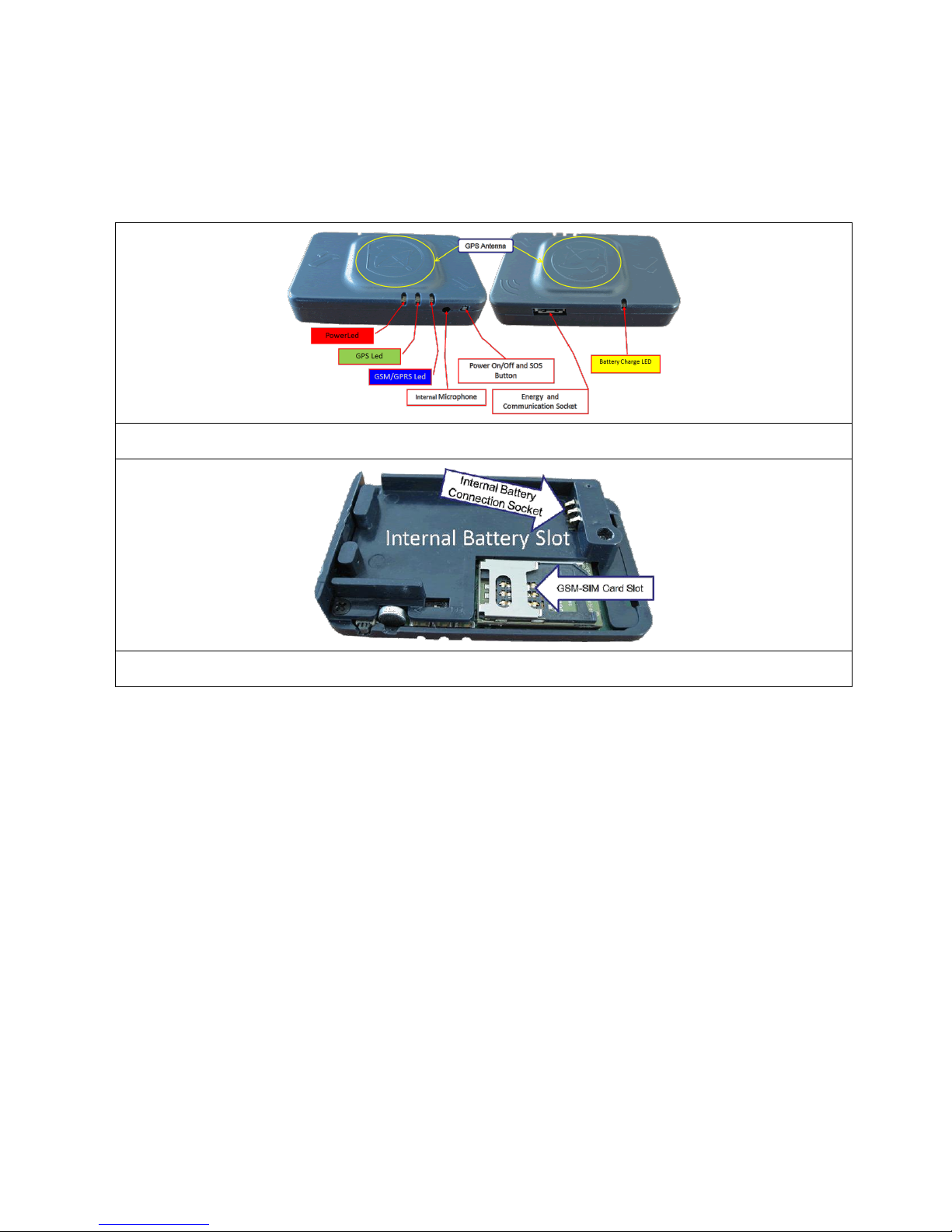
5.1 OVERVIEW ....................................................................................................................................................................8
5.1.1 External Power and Connection Socket ................................................................................................................8
5.1.2 GPS Antenna .............................................................................................................................................................8
5.1.3 On/Off Button ...........................................................................................................................................................8
5.1.4 Internal Microphone.................................................................................................................................................9
5.1.5 Illuminated Leds .......................................................................................................................................................9
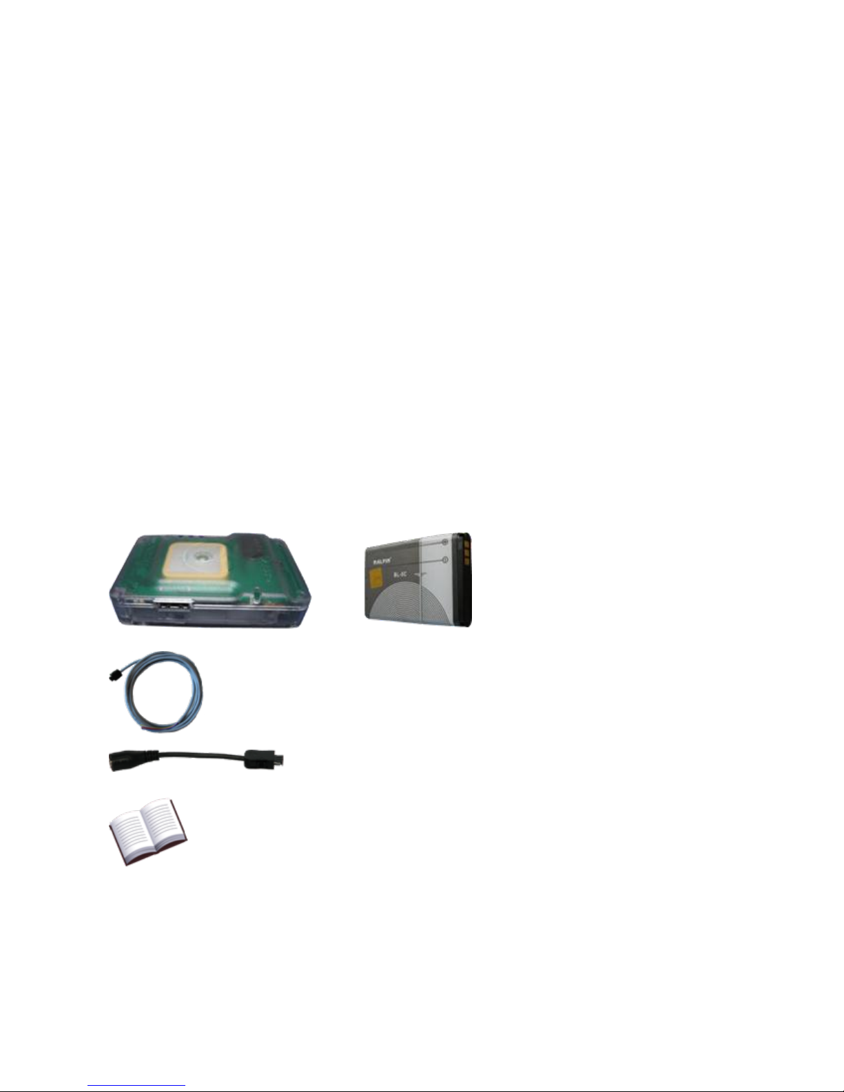
5.1.6 Internal Li-ion Battery............................................................................................................................................10
5.1.7 GSM-SIM Card Socket............................................................................................................................................10
6. INSTALLATION ..........................................................................................................11
6.1 ATTENTION ! IMPORTANT POINTS DURING INSTALLATION .................................................................11
6.2 CABLE CONNECTIONS.............................................................................................................................................11
6.2.1 POWER CABLE (RED).............................................................................................................................................12
6.2.2 EARTH/GROUND CABLE (BLUE)...........................................................................................................................12
6.2.3 IGNITION CABLE (WHITE) ...................................................................................................................................12
6.2.4 PANIC (EMERGENCY CASE) CABLE CONNECTION (GREEN) ...........................................................................12
6.2.5 DATA CABLE CONNECTION (YELLOW) [RX-COM2], BROWN [TX-COM3]) ...................................................12
6.2.6 INPUT (GREY).........................................................................................................................................................12
6.2.7 OUTPUT (PINK) ......................................................................................................................................................13
6.2.8 PLACING THE INTERNAL BATTERY .....................................................................................................................13
7. OPERATION OF THE DEVICE ...................................................................................13
7.1 DESIGNATING GSM NUMBER TO COMMUNICATE WITH DEVICE ...........................................................13
7.1.1 DESIGNATING GSM NUMBER TO COMMUNICATE WITH DEVICE (F60-SB) .................................................13
7.1.2 CANCELLING DESIGNATED GSM NUMBER TO COMMUNICATE WITH DEVICE (F60-SB) ...........................14
7.2 UTILISING THE ELECTRONIC PARK (E-PARK) FEATURE ...........................................................................14
7.2.1 SETTING DEVICE TO PARK POSITION ...............................................................................................................14
7.2.2 DISABLING DEVICE PARK POSITION..................................................................................................................15
7.3 SENDING EMERGENCY CASE MESSAGE............................................................................................................15

ENGLISH
- 2 -
7.4 INQUIRING VEHICLE POSITION INFORMATION THROUGH SMS ..........................................................16
7.5 VOICE TRANSFER FROM DEVICE LOCATION ..................................................................................................17
7.6 UTILISING THE INPUT/OUTPUT FEATURE OF THE DEVICE......................................................................17
7.7 RECEIVING SPEED LIMIT AND RAPID ACCELERATION/SLOWING VIOLATIONS.............................18
7.8 INFORMATING WHEN THE VEHICLE REACHES GEOGRAPHICAL LOCATIONS SPECIFIED (F60-
SN).........................................................................................................................................................................................18
7.9 REPORTING MILEAGE (F60-SN)..........................................................................................................................18
7.10 REPORTING VEHICLE RUNNING TIME (F60-SN) .......................................................................................18
7.11 REPORTING IDLE RUNNING TIME (F60-SN) ...............................................................................................19
7.12 SWITCHING THE FIXED DEVICE TO MOBILE MODE..................................................................................19
7.13 HOW AND WHERE THE DEVICE CAN BE TRACKED.....................................................................................19

ENGLISH
- 3 -
Dear Customer,
We thank you for choosing this product and hope that you will be satisfied with it.
Best Regards,
Fideltus A.Ş.
OVERVIEW TO THE MANUAL
This manual contains information necessary to install, use and preset the Fideltus Vehicle Tracking and Security
System (hereinafter referred to as PERGO) hardware. Please read this manual carefully before installing and
using the device.
Please remember that failure in complying with the information contained herein shall void Fideltus’
responsibility and the warranty of the PERGO product.
Please keep this manual, as it is an important source for the conscious and secure use of the PERGO product.
1. PRODUCT OVERVIEW
PERGO Device
Model F60
Internal Li-ion Battery
Vehicle Fixed Installation Cable
Vehicle lighter socket and 220V power adapter connection
apparatus
Users Manual

ENGLISH
- 4 -
2. WARNINGS
Please read the following carefully before using your device. The company declines all responsibility for issues
that may arise from failure in reading the manual.
□Do not use the device for purposes other than specified in this manual.
□Do not subject the device to strong impacts and swing. Otherwise the device may be harmed.
□Never open the interior lid of the device. Do not tear the warranty labels. This will void the warranty.
□Take care not to get the device wet. Do not spill liquids on the device. This may result in irreparable
damage. If the device has been exposed to liquids in any way, remove the power plug, immediately remove
the battery, dry the liquid with an air pump and contact an authorized service. Never use volatile solutions
such as alcohol and petrol for cleaning.
□Do not leave the device in damp, hot and highly vibrating environments and do not expose to strong
magnetic fields.
□While fitting and removing the connection socket, please hold the box of the device firmly. Especially
when removing the connection socket, remove it by pressing on the catches at the edges of the socket.
Otherwise you may damage the connection socket.
□Keep away from strong magnetic fields as electrostatic discharge may stop or damage the device.
□Do not directly connect the device to power higher than 35 V DC. Use an adapter for 220V.
□Do not attach hardware that has not been approved by the producer.
□External circuit breaker (fuse) should be T 2A.
3. INTRODUCTION
PERGO is a security system software and hardware developed in Turkey by Turkish engineers, which is capable
of tracking the location of anything (vehicle, humans, objects, animals) to which it is attached, of enabling
communication between the object to which it is attached and the tracking centre, and of providing vehicle and
personal security.
PERGO has been designed mainly to ensure the personal and property safety of its users.
PERGO is not only a vehicle tracking system. The personal and property safety of the user is ensured through 5
different emergency signals produced by PERGO.

ENGLISH
- 5 -
4. WORKING MODELS
Pergo device has different types of uses for different purposes. These differences in use are explained below.
Operation with connection to the Center
F60-N
Operation with no connection to the Center
F60-B
It needs to connect to a specific center to detect the
location of your device at any time and to report its
previous locations. As long as your device works, it
connects to the predefined central server using
GSM/GPRS infrastructure and reports location by the
preset time intervals and distances.
Your device only communicates with your GSM
number. It processes SMS commands from your GSM
number and sends an SMS to your GSM number, if
set, in case of a violation. Your device does not
connect to any central server and does not send
location information.
In both cases above, your device may be used by assembly to both mobile (with no need for an external power
supply) and motorized vehicle.
Mobile Use
F60-MN / F60-MB
Use by Fixed Assembly to the Vehicle
F60-SN / F60-SB
It needs no external power connection for operation. It
may be turned on/off from the on/off button. In cases
where it is not turned off and it stays immobile for a
long time, it turns itself off automatically and it's turned
on automatically when it's moved.
When the vehicle it is connected to is activated, it is
turned on automatically and it is turned off
automatically when the vehicle ignition is inactive.
The on/off button may not be used for turning on/off
the device. When fixed assembly is made for the
vehicle, the vehicle generates a report about the
relevant cases of violation. The assembly to the
vehicle should take place as set out in the assembly
guide.
4.1 PERGO TECHNICAL SPECIFICATIONS
HARDWARE (Features generally apply to the F60 model)
GPS Features
Antenna
Internal (Passive) Antenna
GPS Precision
50 Channels, -160 dBm
Positioning System
GPSL1, GALILEOL1, SBAS, WAAS, EGNOS, MSAS,
GGAN
GSM Modem Features
GSM Modem
Class 10 Quart Band 800/900/1800/1900
Antenna, SIM Card
Internal

ENGLISH
- 6 -
Physical Features
Weight (battery excluded)
Size
Box
45 gr.
72x46x17 mm, 55 cm3
IP44
Other Features
Operating Voltage
6V DC - 35V DC
Operating Temperature
-30°C..+70°C (Battery Excluded) / -20°C..+60°C
Energy consumption normal/ Data Transfer / Sleep
Mode
180 Mw /1-2 W / 0,1-3 mW
Automatic awakening from sleep mode
Yes
Automatic operation
Yes
Fixed: Starts/shuts down according to vehicle
ignition data.
Mobile: Can be turned on/off via button. If not
turned off, it automatically switches to sleep mode
if there is no motion.
Time taken to connect to GPRS
5-25 seconds
GSM Cell Data Notification
Yes
Stopping vehicle from a distance
Yes. An optional ROLE connection should be made.
The vehicle can be stopped through an SMS sent
from the authorised mobile phone or through a
desktop application software.
Number of external connection connectors
1 (Power, Ignition, RS232, Emergency, ROLE,
Fuel/Temperature)
Colour classification in connectors
A single connector used for all connections.
Visual Status Report
Leds in 4 different colours (Recharge, Power, GPS,
GSM)
Microphone
Internal
Internal Battery
Li-ion
Recharge Feature
Yes
Off-Line Position recording
Yes - a recording capacity of 100.000 positions.
External Emergency Connection Port
Yes
Voice communication
One side / can be started and ended automatically

ENGLISH
- 7 -
and by the centre in the case of emergencies.
Firmware updateable through GPRS
Yes –Automatic version check and updating by the
centre
Reading and changing operating settings through
GPRS
Yes
Position Compression
Yes –Data regarding Latitude, Longitude, Speed,
Heading, Altitude, Number of Satellites, Accuracy
of Position, and Distance information are sent in a
total size of 15 byte.
Smallest position notification frequency
1 Second
Communication with the Centre
TCP/IP - TCP Socket
Auxiliary connection support
Yes. Establishes communication via auxiliary
mapped GPRS connection if primary mapped GPRS
connection fails to connect to centre.
Feature of operating without connection to centre
Yes. Does not continuously notify position. Sends
position data to mobile phone through sms only
when requested.
Performs automatic sms notification in alarms
and violations.
Alarms Generated
Alarms Generated
Emergency,
Change in external power source,
Being towed,
Unauthorised Use,
Detecting motion in vehicle while in E-Park
Restriction Controls
Distance Calculation, Speed Limit, Idle Waiting
Period, Rapid acceleration and deceleration,
Reaching geographical coordinates, Sudden
decrease in fuel level, Magnetic sensor value
change, Task Area, Course, and Operation Time
control

ENGLISH
- 8 -
5. PERGO INTRODUCTION
5.1 OVERVIEW
Figure 1 –Upper view
Figure 2 –Inside view
5.1.1 External Power and Connection Socket
It is the socket where the bunch of cables providing PERGO with external power and enabling the connection of
the ignition switch, the emergency pedal, other hardware in the vehicle and input/output relay connections in
the vehicle, is connected. The connection port is also used to connect the device to a computer in order to
update its software and perform its operation settings. Please see the Installation section for information on
where each coloured cable plugged into the connection port should be fitted in the vehicle.
5.1.2 GPS Antenna
The GPS module enabling PERGO to receive signals from GPS satellites and to fix its location on earth is located
next to the antenna. PERGO must be installed allowing the GPS antenna to face the sky. No metal and similar
object must be placed on the antenna, as such objects may prevent the antenna from receiving signals.
5.1.3 On/Off Button
The On/Off button varies according to use type.

ENGLISH
- 9 -
PERGO MODELS
F60-S*
F80-M*
Used for designating the GSM number to be used in
communication or for cancelling such designated
number.
Not used for turning the device on or off. These
models, which must be installed as fixed to vehicles,
start operating automatically when the vehicle is
started and stop automatically when the ignition switch
is turned off.
Used for starting and stopping PERGO, and for
transmitting an emergency message.
Due to device’s motion sensor, the device switches to
sleep mode and shuts down if the device is motionless
for a certain period, even if it is not turned off from the
button. It restarts automatically when motion is detected
again.
5.1.3.1 Starting PERGO (F60-M*)
Keep pressed until the red and blue leds on the right-hand side of the On/Off button turn on one after the other
(2 sec.).
5.1.3.2 Stopping PERGO (F60-M*)
Keep pressed until the green and red leds on the right-hand side of the On/Off button turn on one after the other. (It may
be required to press the button between 2 and 7 seconds depending on the status of GPS and GSM modules.)
In the case the on/off switch is set for emergency transfer and If the button is pressed in order to shut down the
device and the on/off button is released before the green and red leds turn on, the device shall send an
emergency signal to the centre to which it is connected.
5.1.4 Internal Microphone
Internal microphone is activated after an emergency an automatic preset number call is made to the Emergency
Tracking Center and enables transfer of ambient sounds to a predefined number on the device.
5.1.5 Illuminated Leds
There are 4 different illuminated LEDs on PERGO. These are recharge LED (yellow), power LED (red), GPS LED
(green), and GSM/GPRS LED (blue). These LEDs indicate the operation status of the device. The meanings of
the activation and deactivation of the LEDs on the device have been explained below.
LED
STATUS
REMARKS
RECHARGE
YELLOW
Blinking
External power connected but internal Li-ion battery not installed.
Off
Internal Li-ion battery installed and battery charge level is 100%.
This is the normal light indication.
Always On
Internal Li-ion battery is being recharged.
POWER
RED
Always On
Malfunction. (Motion sensor or memory (flash) failure.)
Lights up at 2 sec.
intervals
The device is functioning properly.

ENGLISH
- 10 -
Lights up at 0,5 sec.
intervals
Emergency mode.
Off
Device off.
GPS
GREEN
Always On
GPS failed.
Lights up at 2 sec.
intervals
Position not yet fixed.
Off
A position data fix has been obtained from GPS satellites.
GSM/GPRS
BLUE
Always On
Sim card not installed, GSM hardware has malfunctioned or sim
card blocked.
Lights up at 2 sec.
intervals
Attempting connection to tracking centre. (GSM on but GPRS
connection not yet achieved)
Off
Tracking centre connection successful.
5.1.6 Internal Li-ion Battery
There is a li-ion rechargeable battery inside the device. The internal battery is used for detecting and tracking
operations carried out on the battery systems of the device or dismantling of the device for a certain period.
When the device is fixed on the vehicle it will operate without the batteries. The device having batteries
installed should not be subjected to direct sunlight for a long period.
5.1.7 GSM-SIM Card Socket
For the device to communicate with the center it is connected to and transfer location information, a GSM SIM
card should be installed into it. It is adequate that the installed SIM card supports one of the Quard Bant
(850/900/1800/1900 Mhz) communication of its operator.
5.1.7.1 Disabling the PIN inquiry of the GSM-SIM Card (WARNING)
Before the GSM-SIM card is installed on the device, the PIN inquiry option should be disabled through
another mobile phone. Otherwise your GSM-SIM card may be blocked. Fitting a SIM card the PIN inquiry of
which is disabled shall enable the opening of the telephone without the necessity to enter the PIN code. If the
telephone on which the SIM card is installed requires a PIN code upon startup, this means that PIN inquiry is
not disabled. Our firm shall not be held responsible for malfunctions (SIM blockage) caused by failure in
disabling PIN code inquiry. For a sound operation either the PIN inquiry of the SIM card should be cancelled or
the PIN number of the SIM card should be designated in the device. Please contact your service provider to
enter the PIN code to the device.

ENGLISH
- 11 -
6. INSTALLATION
In mobile operation, installation is not required. You can use the device after charging the batteries with a
charge adaptor you may provide from your service provider or manufacturer or with the lighter socket adaptor.
For fixed operation, use the detailed installation guide that is provided with the product. Provide that the
installation is made by a technical service personnel or in a car maintenance station.
6.1 ATTENTION ! IMPORTANT POINTS DURING INSTALLATION
□Install the GPS antenna facing upwards the sky.
□Be careful that metal and other similar objects are not placed over device.
□The installation of Device should be performed by specialists informed about the electrical system of
your vehicle.
□The external power input to be connected to Device must not exceed DC 35 V DC.If so, a regulator
decreasing the power to 35 V DC should be used.
□Do not keep high radio frequency emitting devices close to Device.
□In the event that the GSM-SIM card to be installed on the vehicle, disable PIN inquiry/make sure that
PIN inquiry is disabled. (Disabling the PIN Inquiry of the GSM-SIM card)
6.2 CABLE CONNECTIONS
In fixed operation of the device on the vehicle, make the connection as shown in the figure below. In the
connection socket of the vehicle there are a bunch of 8 cables in different
colors. Functions and connections of each one of these cables are described
below.
Basically connecting 3 of the cables (red, blue and white) is enough for the device to operate.
Battery Power (+) : Continuous DC 6 V DC –
35 V DC energy is necessary.
Ignition Power (+) : 6 V DC –70 V DC energy
is necessary only when the ignition switch is on.
Figure 3 –PERGO Vehicle Fixed Connection Diagram

ENGLISH
- 12 -
4 of the connection cables coming out of PERGO (white, green, red, and blue) should be connected to their
relevant places on the vehicle fuse board. The cable connections should be made firmly in order to avoid vehicle
and device damage caused by arc (electricity jump due to failure in connecting cables firmly). The devices do
not have electronic installations that may harm other devices working in the vehicle (air conditioning, computer
etc.). Please keep in mind that defects arising from failure in connecting the connection cable ends properly
shall not be covered by the warranty and make sure that the installation should be performed by automobile
electricians or authorised services.
No energy supply cable should be connected directly to a supply line that is not connected through a fuse-box
and that is not protected by a fuse. Although the device has reverse current and overload protection, it should
be remembered that the device may be damaged due to connection problems.
6.2.1 POWER CABLE (RED)
The power cable is the red cable within the cable bunch, which transmits Device’s operating energy. This cable
is connected in the fuse board to a place in which there is always DC power between 6 V DC and 35 V DC
(while the vehicle is running or not).
6.2.2 EARTH/GROUND CABLE (BLUE)
It is the blue cable within the cable bunch coming from Device. This cable must be connected to the
earth/ground end on the fuse board.
6.2.3 IGNITION CABLE (WHITE)
It is the white cable within the cable bunch coming from Device. This cable is connected to a place which supplies 6 V
DC –35 V DC power when the ignition key is turned on but stops supplying power when the ignition key is
turned off. Installed fixed models operate by sensing the starting or stopping of the vehicle and generate the
necessary alarms. In order that the device succeeds in performing these, the ignition connection cable should
be connected to a place with the above characteristics.
6.2.4 PANIC (EMERGENCY CASE) CABLE CONNECTION (GREEN)
It is the green cable within the cable bunch coming from Device. The panic cable coming from PERGO is connected to
the emergency button or pedal. The other cable end on the emergency button or pedal is connected to a place
on the fuse board, which continuously supplies 6 V DC –35 V DC power. It can be connected to the same place
with the Device power cable (red).
6.2.5 DATA CABLE CONNECTION (YELLOW) [RX-COM2], BROWN [TX-COM3])
These cables are used in communicating with a computer or other hardware developed by the producer
(proximity reader, LCD text unit, Multiple I/O module, video camera etc.). The package of the other hardware
shall include the wiring diagram necessary for connecting other hardware supplied by the producer with the
Device.
6.2.6 INPUT (GREY)
Electrical or magnetic switches are used as shown in Fig-3 it is used to inform the center about the state
changes due to the electrical or magnetic switches.
Transferring information about opening and closing of the motor hood, fuel cap, vehicle doors or lifting truck

ENGLISH
- 13 -
dumpers up and down are some examples of operation.
6.2.7 OUTPUT (PINK)
Must be used together with the relay system. Used in starting or stopping other hardware connected to the relay by
activating the installed relay system by the tracking system or through SMS messages sent by authorized persons to the
tracking centre. Stopping the vehicle from a distance when the relay output ends are connected to the fuel shut-off system
of the vehicle can provide an example for the field of use.
6.2.8 PLACING THE INTERNAL BATTERY
The PERGO package contains 1 rechargeable Li-ion battery. This battery must be
installed as shown in the figure by opening the rear lid, placing the battery and
closing the lid.
7. OPERATION OF THE DEVICE
7.1 DESIGNATING GSM NUMBER TO COMMUNICATE WITH DEVICE
In case the device is to communicate with any GSM number, the installed GSM line should have voice feature.
GSM lines that has only data feature should not be used.
At least 1 GSM number should be authorized to be able to use E-PARK feature in F60-SN model and to enable
all communications in F60-SB model. 33 GSM numbers can be authorized to model F60-SN device, whereas 3
GSM numbers can be authorized for model F60-SB.
All GSM numbers that will communicate with F60-SN is made via a system web interface.
7.1.1 DESIGNATING GSM NUMBER TO COMMUNICATE WITH DEVICE (F60-SB)
The ignition key of the vehicle must be turned off so that the authorized GSM number can be designated.
Perform the following at least 30 seconds after the vehicle ignition key is turned off.
□If another GSM number was designated before, such number must be cancelled first. Read the section
CANCELLING DESIGNATED GSM NUMBER TO COMMUNICATE WITH PERGO for the cancellation procedure.
□Hold down the on/off button,
□Call the GSM number installed in Device from the mobile phone that you wish to set as the authorized
number,
□When the blue led on Device lights for 3 seconds this means that the calling authorized number has
been recorded.
□If the red led on PERGO lights for 3 seconds this means that an authorized gsm number has already
been designated for PERGO. Read the section CANCELLING DESIGNATED GSM NUMBER TO COMMUNICATE
WITH THE DEVICE for cancelling the designated gsm number.

ENGLISH
- 14 -
7.1.2 CANCELLING DESIGNATED GSM NUMBER TO COMMUNICATE WITH DEVICE (F60-SB)
The vehicle ignition key must be turned off so that a previously authorized GSM number can be deleted. Perform
the following at least 30 seconds after the vehicle ignition key is turned off.
□Hold down the On/Off button,
□Call the GSM number installed on the device from the GSM number recorded previously as the
authorized number,
□When the green led on the device lights for 3 seconds this means that the authorized number
designation procedure has been cancelled.
If the calling GSM number is not the authorized number the red light led will light for 3 seconds. In such case
the authorized number cancellation procedure will not take place. For the cancellation procedure, a call must be
made from the previously designated authorized number. If you do not know the previously designated
authorized number please contact the company authorized service for the cancellation procedure.
7.2 UTILISING THE ELECTRONIC PARK (E-PARK) FEATURE
E-Park is a security precaution developed to inform vehicle owners in the case of the theft or unauthorized use (starting
vehicle through hotwiring or key) of their vehicles. This feature is disabled by default. In order to use the E-Park feature, the
device must first recognize a GSM number that it will use in communication. The procedure for designating a GSM number
has been explained under the section DESIGNATING GSM NUMBER TO COMMUNICATE WITH DEVICE.
MODELS
F60-SB
F60-SN
Starting the
Manual E-Park
Feature
An SMS containing the text “EPARK ON” is sent to the GSM number
installed in the device.
When Device is in
operation and when it
connects to the
centre, the
procedures for using
or cancelling the E-
Park feature and for
designating the gsm
number to
communicate with the
device must be
performed.
Starting the
Automatic E-
Park Feature
An sms containing the text “EPARK AUTO XX” shall be sent to the GSM
number installed in the device. The value indicated as XX shows the
minutes following the turning off of the ignition key before the automatic
e-park status is activated. This number may be between 1 and 99. If the
EPARK AUTO feature is used the device shall initiate automatic park
status when the ignition key of the vehicle is turned off.
Disabling the E-
Park Feature
In order to stop using the E-Park feature, an sms containing the text
“EPARK OFF” must be sent to the GSM number installed in the device.
Warning: All sms texts to be sent to the device must be written using capital letters.
7.2.1 SETTING DEVICE TO PARK POSITION
The procedure for setting Device to the E-Park position must be used according to the setting made while
initiating the use of the E-Park feature. If the automatic E-Park feature is used, making a call shall not be
necessary for setting the vehicle to park position. The automatic E-park position becomes active after the
ignition key of the vehicle is turned off and the duration set during the setting procedure has expired. In such
case you will have to disable the park position by calling the GSM number installed in Device every time you use
the vehicle.

ENGLISH
- 15 -
If setting Device to park position has been achieved manually, the following step should be followed at least 30
seconds after the ignition key of the vehicle is turned off.
The GSM number installed in Device is called from the GSM number designated for Device and the call is ended
after a few ring tones. The device is now in parking position. If the vehicle is started through the vehicle key or
through hotwiring, an automatic sms message will be sent to the designated gsm number in the F60-SB model.
In the F60-SN model the centre shall be informed and the necessary security procedures shall be performed.
When the call has been made, if the caller shuts the device down before ending the call, this will cause the
device to end the park position. Repeat the procedure to bring into parking position.
7.2.2 DISABLING DEVICE PARK POSITION
Before starting the vehicle;
The number of the GSM installed in Device is called from the GSM (authorised) number designated for Device.
When the call reaches the device it is automatically ended by the device. The device has now disabled the
parking position.
If the vehicle is started before disabling the park position in cases where the vehicle is in park position, in the
F60-B model an sms message is sent to the GSM number designated for the device, regarding unauthorised
use. In the F60-SN model the centre shall be informed and the necessary security procedures shall be
performed.
If the call has not been ended automatically by the device when the call has been made, this means that the
device has enabled park position. Repeat the procedure to disable parking position.
7.3 SENDING EMERGENCY CASE MESSAGE
The task of sending an emergency case alarm is performed with a single button or pedal. The task of sending
an emergency alarm is activated by pressing a button or a pedal for 3 seconds (this period is adjustable)
performed with a single button or pedal.
PERGO MODELS
F60-S*
F80
In order that the emergency case messages can be transmitted, the
emergency pedal or button must be installed on the related cables on the
connection port (for installation, see the section “Installation”). An
emergency message is sent by pressing the installed button or a pedal for
3 seconds (this period is adjustable)
If the on/off switch is pressed and
released before shutdown is
completed (green and red leds glow
respectively) an emergency message
is released if required settings are
made.
If the device is in emergency mode, the red led shall blink once every 0.5 seconds. F60-*N models in emergency
mode transmit position data to the tracking centre every 10 seconds. The device automatically ends the
emergency mode after 300 seconds and resumes normal position information.

ENGLISH
-16 -
7.4 INQUIRING VEHICLE POSITION INFORMATION THROUGH SMS
PERGO MODELS
F60-*B
F60-*N
E-PARK ENABLED
E-PARK DISABLED
The GSM number installed in Device
is sent an SMS message containing
the text “POS” (in capital letters) by
the GSM number designated for
Device. The device replies to the
GSM number sending the sms
message through an sms message
indicating the position data in
latitude, longitude, speed and
heading.
The GSM number installed in
PERGO is called by the GSM
number designated for
PERGO. The call is ended
after 1-3 rings. The device
sends the position data as
latitude, longitude, speed
and heading in an sms
message.
In the sms message sent by Device to the designated gsm number,
there is no data based on the municipalities’ address system. The
SMS content contains the geographical data of the location where
the device is positioned. In order to understand where these
coordinated correspond to, you may use one of the following
methods.
If you are using Google
Earth, you can write in the
box the coordinate data
written next to LAT: and
LNG: in the message sent via SMS, using , (commas) inbetween (.
(periods) should be used instead of the , (commas) between the
values) and can thus display the coordinates on map.
You can view the coordinates on the digital
map by entering the data obtained from
the sms message into the box found in the
digital map display section on the webpage you received server, the
data next to LAT: being entered into the latitude box and the data
next to LNG: to the longitude box (. (periods) should be used
instead of the , (commas) between the values).
If you send the message that you have received via sms to the SMS
server you received server, the SMS server will send you the
address located in these coordinates via SMS.
The number plate of the vehicle
identified in the system of the device
shall be sent via sms to the sms call-
centre of the corporation from which the
tracking service is received. If the GSM
number authorization settings have been
identified in the tracking centre, the
position data of the vehicle shall be sent
to the requester as municipality address
information via sms.

ENGLISH
-17 -
7.5 VOICE TRANSFER FROM DEVICE LOCATION
PERGO MODELS
F60-*B
F60-*N
E-PARK ENABLED
E-PARK DISABLED
The number designated in the device is
called automatically in case the emergency
button or pedal (if installed) is pressed if
required settings are made.
A voice connection can be established by
sending a command to the device if required
authorization is given on the web tracking
interface.
The GSM number installed in
Device is sent an SMS message
containing the text “CALL” (in
capital letters) by the GSM
number designated for Device.
The device calls the GSM number
sending the sms message.
Default line connection period is 3
minutes. If a longer period
connection is required a time
parameter in seconds, like “CALL
1000” should be written in the
SMS content.
The GSM number installed in
Device is called by the GSM
number designated for Device
and waits until the call is
answered.
The answering period is the
duration of 5 rings. The device
will automatically end the call 3
minutes after the call has been
answered.
7.6 UTILISING THE INPUT/OUTPUT FEATURE OF THE DEVICE
In order to use this feature that operates by stopping the vehicle by cutting the fuel system of the vehicle, the
installation necessary must be performed as explained in the section regarding cable connections.
PERGO MODELS
F60-SB
F60-SN
In order that the GSM number designated for Device opens the
content, the text “ROLE ON” should be sent via SMS to the GSM
number installed on Device, and the text “ROLE OFF” should be
sent in order to close the content.
When the SMS is received and the command is executed by the
device, a reply shall be sent to the designated gsm number
notifying that the procedure was carried out.
The system under this feature of the device
can be remotely opened or closed through
the active tracking centre or a web interface.
The ignition key of the vehicle has to be
turned on for the feature to be used.
In order to open content, the message
“ROLE1 ON PLAKA” should be sent via
SMS to the sms call centre of the corporation
from which service is received, and the
message “ROLE1 OFF PLAKA” should be
sent in order to close the content.

ENGLISH
-18 -
7.7 RECEIVING SPEED LIMIT AND RAPID ACCELERATION/SLOWING VIOLATIONS
It is a feature used to inform the vehicle owner when the vehicle has violated the designated speed limit or has
exceeded the defined difference of speed within 2 consecutive seconds. By default, these values are not activated. If
you wish to be informed of violations, please have the necessary settings performed as follows.
PERGO MODELS
F60-SB
F60-SN
An SMS message, the content of which is in the format of "OPT
000 00," should be sent to the GSM number installed in Device. If
the SMS content is sent as explained above, the speed limit and
rapid acceleration/deceleration control will be disabled. The 3-digit
value following the word OPT indicates the speed limit with which
the vehicle must comply, and the following 2-digit value indicates
the difference in speed between two speeds, which must be
complied with. The message to be sent to the device must consist
of 10 characters including the spaces. For instance, if the speed
limit to be set as the upper limit is 90 km/h and the difference
between the two speeds is 25 km/h, the content of the message
should be “OPT 090 25”.
The tests performed have shown that the difference between two
speeds should be set above 20-25 km/h for the detection of rapid
acceleration and deceleration of the vehicle.
The speed limit and rapid
Acceleration/deceleration speed kept by the
device can be changed through a command
from the active tracking centre or the web
interface.
When the defined violation is detected on
the device, the system center SMS server
informs all users designated on the system
about the vehicle causing violation.
7.8 INFORMATING WHEN THE VEHICLE REACHES GEOGRAPHICAL LOCATIONS
SPECIFIED (F60-SN)
The designation of 200 geographical locations for Device is performed by the system web interface. In the event
that the vehicle on which the device is installed reaches the defined geographical locations, the device informs the
system centre. The times in which these locations were reached can also be received as reports through the web
interface.
7.9 REPORTING MILEAGE (F60-SN)
The device continuously calculates the distance travelled by the vehicle with a margin of error of ±%5 and informs
the system centre. This mileage data can also be received as a report through the web interface.
7.10 REPORTING VEHICLE RUNNING TIME (F60-SN)
This feature can be used only in the F60 model. The device calculates the time in which the ignition key of the vehicle
was turned on and informs the system centre. The running report data can be obtained in detail through the web
interface.

ENGLISH
-19 -
7.11 REPORTING IDLE RUNNING TIME (F60-SN)
The long-duration standstills performed by the vehicle when the ignition key is turned on are reported to the
system centre. The idle running report data can be obtained in detail through the web interface.
7.12 SWITCHING THE FIXED DEVICE TO MOBILE MODE
The device has an automatic contact perception system. After the mobile device is installed and perceives the
current after the ignition switch is turned on, it is automatically reset and switches to an operating mode where it
will produce some special reports on vehicle operation working on the vehicle battery supply. In this mode it is
impossible to turn off the device using the on/off switch. The device only turns on and off with the standby energy
of the vehicle. All LED’s of the device goes off when the connection cable is dismantled but the operation
continues. If the fixed device is decided to be used in mobile mode, the battery of the device is displaced after the
current supply connection is dismantled, and on/off switch is pressed continuously and the battery is re-installed.
The button is released after 5-10 seconds. After this operation the device switches to mobile mode and could be
turned on an off using the on/off switch.
7.13 HOW AND WHERE THE DEVICE CAN BE TRACKED
There is no continuous tracking feature in F60-*B models. These models can only communicate via an identified
GSM number and with SMS. In F60-*N models, tracking and reporting can be done through an internet web site
designated by the supplier of the device. You have to set a username and password to be able to use the web
interface. The website address for tracking and reporting used by Pergo devices that operate in Turkey is
http://vts01.pergo.com.tr. You should start with the “new user” link after you enter the website if you do not have a
predefined username and password. Then you can enter the serial number and page verification code of the
device you have purchased and continue to the next page to identify your username and password. After you
complete identifing your username and password a verification message will be sent by the system to the e-mail
address you have defined during registration. You account will be activated when you click the link inside the
message you received. From now on you can define other devices you can set up new groups and users, receive
reports and authorize selected users to track vehicles. You can have further information on these procedures by
downloading the “Web Using Guide” to your computer after you log in the website.
Other manuals for F60
1
Table of contents