Philips AX 2200 User manual

PRODUCT FAMILY FOCUS – BASIC
Handling chip components................................................1-1
Technical specification ......................................................2-1
Measuring setup................................................................2-1
Connections and controls..................................................2-2
Instruction for use.......................................................2-3..2-4
Accessories.......................................................................3-1
Service tools......................................................................3-1
Blockdiagram - Set ............................................................4-1
Block diagram - Intergrated Circuits...........................4-2..4-6
Circuit diagrams
Control part ...................................................................5-1
Supply / Servo part........................................................5-2
CD / Audio part..............................................................5-3
Layout diagrams
Componentside view.....................................................5-4
Copperside view............................................................5-5
Keyboard
Circuit diagram..............................................................6-1
Layout diagram .............................................................6-1
Exploded view ...................................................................7-1
Mechanical partslist...........................................................7-1
Electrical partslist...............................................................8-1
©3140 785 32260
Published by YT 0251 Service Audio Printed in The Netherlands Subject to modification
Portable Compact Disc Player
CLASS 1
LASER PRODUCT
AX2201
all versions
TABLE OF CONTENTS
©Copyright 2001 Philips Consumer Electronics B.V. Eindhoven, The Netherlands
All rights reserved. No part of this publication may be reproduced, stored in a retrieval
system or transmitted, in any form or by any means, electronic, mechanical, photocopying,
or otherwise without the prior permission of Philips.
AX2200

1-1
HANDLING CHIP COMPONENTS
© WARNING
All ICs and many other semiconductors are susceptible to
electrostatic discharges (ESD). Careless handling during
repair can reduce life drastically.
When repairing, make sure that you are connected with the
same potential as the mass of the set via a wristband with
resistance. Keep components and tools at this potential.
f ATTENTION
Tous les IC et beaucoup d´autres semi-conducteurs sont
sensibles aux décharges statiques (ESD). Leur longévite
pourrait être considérablement écourtée par le fait qu´aucune
précaution nést prise à leur manipulation.
Lors de réparations, s´assurer de bien être relié au même
potentiel que la masse de l´appareil et enfileer le bracelet
serti d´une résistance de sécurité.
Veiller à ce que les composants ainsi que les outils que l´on
utilise soient également à ce potentiel.
d WARNUNG
Alle ICs und viele andere Halbleiter sind empfindlich
gegenüber elektrostatischen Entladungen (ESD).
Unsorgfältige Behandlung im Reparaturfall kann die
Lebensdauer drastisch reduzieren.
Sorgen Sie dafür, daß Sie im Reparaturfall über ein Puls-
armband mit Widerstand mit dem Massepotential des
Gerätes verbunden sind.
Halten Sie Bauteile und Hilfsmittel ebenfalls auf diesem
Potential.
ñ WAARSCHUWING
Alle IC´s en vele andere halfgeleiders zijn gevoelig voor
electrostatische ontladingen (ESD).
Onzorgvuldig behandelen tijdens reparatie kan de levensduur
drastisch doen vermindern. Zorg ervoor dat u tijdens reparatie
via een polsband met weerstand verbonden bent met hetzelfde
potentiaal als de massa van het apparaat.
Houd componenten en hulpmiddelen ook op ditzelfde potentiaal.
i AVVERTIMENTO
Tutti IC e parecchi semi-conduttori sono sensibili alle scariche
statiche (ESD).
La loro longevità potrebbe essere fortemente ridatta in caso di
non osservazione della più grande cauzione alla loro
manipolazione. Durante le riparationi occorre quindi essere
collegato allo stesso potenziale che quello della massa
delápparecchio tramite un braccialetto a resistenza.
Assicurarsi che i componenti e anche gli utensili con quali si
lavora siano anche a questo potenziale.
©
Safety regulations require that the set be restored to its
original condition and that parts which are identical with
those specified be used.
Safety components are marked by the symbol
i
Le norme di sicurezza estigono che l´apparecchio venga
rimesso nelle condizioni originali e che siano utilizzati i
pezzi di ricambiago identici a quelli specificati.
Componenty di sicurezza sono marcati con
ñ
Veiligheidsbepalingen vereisen, dat het apparaat in zijn
oorspronkeliijke toestand wordt teruggebracht en dat
onderdelen, identiek aan de gespecificeerde, worden toegepast.
De Veiligheidsonderdelen zijn aangeduid met het symbool
sVarning !
Osynlig laserstrålning när apparaten är öppnad och
spärren är urkopplad. Betrakta ej strålen.
∂Advarsel !
Usynlig laserstråling ved åbning når sikkerhedsafbrydere
er ude af funktion. Undgå udsaettelse for stråling.
ßVaroitus !
Avatussa laitteessa ja suojalukituksen ohitettaessa olet alttiina
näkymättömälle laserisäteilylle. Älä katso säteeseen !
f
"Pour votre sécurite, ces documents doivent être utilisés par
des spécialistes agréés, seuls habilités à réparer votre
appareil en panne".
ESD
SAFETY
d
Bei jeder Reparatur sind die geltenden Sicherheitsvor-
schriften zu beachten. Der Originalzustand des Gerätes
darf nicht verändert werden. Für Reparaturen sind Original-
ersatzteile zu verwenden.
Sicherheitsbauteile sind durch das Symbol markiert.
f
Les normes de sécurité exigent que l`appareil soit remis
à l`état d`origine et que soient utilisées les pièces de
rechange identiques à celles spécifiées.
Les composants de sécurité sont marqués
CLASS 1
LASER PRODUCT
©
DANGER: Invisible laser radiation when open.
©
After servicing and before returning the set to customer
perform a leakage current measurement test from all
exposed metal parts to earth ground, to assure no
shock hazard exists.
The leakage current must not exceed 0.5mA.
AVOID DIRECT EXPOSURE TO BEAM.

1-2
TECHNICAL SPECIFICATION
General
Dimensions (WxHxD) : 128x31x141 mm
Weight without batteries : 205 g
Power supply modes
DC-in socket : 2.5 - 6.0V
Primary batteries (2xLR6) : 1.8 - 3.6V
Rechargable batteries : 1.8 - 3.6V
Battery lifetime
Battery level detection
Battery empty : 1.9V nom. +100/-100 mV
Current consumption CDDA-playback
Shock resistance
+X/-X direction : ≥5 g
+Y/-Y direction : ≥5 g
+Z/-Z direction : ≥up to 10 g
Headphone out (measured with 16Ωload, DBB/ESP off)
Output power (THD=10%) : 2x4.5mW (+1/-3dB)
Frequency response (1mW) : 100Hz-20kHz within 6dB
S/N ratio (unwght) : ≥78dB (81dB typ.)
S/N ratio (A-wght) : ≥82dB (84dB typ.)
THD+N (1kHz, 1mW) : ≤1% (0.2% typ.)
Channel crosstalk (1kHz, no load): ≤33dB (33dB typ.)
Channel unbalance (-40dB) : ≤4dB
Volume attenuation (1kHz) : ≥60dB
Dynamic Bass Boost DBB
Laser
Output power : <5mW (3mW typ.)
Wavelength : 780nm
Measurement setup
Use Audio Signal disc SBC429 4822 397 30184
Low pass filterDUT S/N and distortion meter
L
R
i.e. Sennheiser UPM550
with FF-filter
Level meter
i.e. Sound Technology ST1700Bi.e. 4822 395 30204
22kHz
13th order
EGATSBBD esnopserycneuqerF
zHk36 zHk1 zHk01
DBB Bd5+ ±Bd2Bd0 ±Bd2Bd0 ±Bd2
EDOMNOITAREPO )V5.4(YLPPUSNI-CD )V52.2(YLPPUS.TTAB
edom-yalP.pytAm0130
edom-pmuJ.pytAm160
.pytAm0160
.pytAm200
yb-dnatS n.a. n.a.
EPYTYRETTAB
≥h4 ).pyth6(
≥h14 ).pyth18(
Normal Carbon
batteries 2 x R6
Normal Alkalite
batteries 2 x LR6

2-1
1
#
$
$
1
OPE
N
VOL
E
OFF
•
R SUME
•HO LD
O
UT
L
INE
/
@
!
5
6
7
48
3
2
0
9
CLASS 1
LASERPRODUCT
4
4
9
2.
1.
OPE
N
VOL
E
OFF
•
RSUME
•
HOLD
O
UT
L
INE
/
4
HOLD ➟ OFF
5
PLAY
6VOL
E
/
9
E
/
4
4
9
OPE
N
VOL
O
UT
NE
/
3#
OPE
N
VOL
O
UT
NE
/
9
OPE
N
VOL
!!!
4
4
9
E
OFF
•
RSUME
•
HOLD
L
INE
/
O
UT
OPE
N
VOL
4
4
9
E
OFF
•
RSUME
•
HOLD
L
INE
/
O
UT
OPE
N
VOL
4
4
9
E
OFF
•
RSUME
•
HOLD
L
INE
/
O
UT
2p
1
QUICK START MISE EN SERVICE RAPIDE
English CONTROLS / POWER SUPPLY
1OPEN 2..............opens the CD lid
2∞.......................skips and searches CD tracks backwards
3§.......................skips and searches CD tracks forwards
4DBB.....................switches the bass enhancement on and off. This button also
switches acoustic feedback (the beep) on/off when it is
pressed for more than 2 seconds
5PROG...................programs tracks and reviews the program
6............................display
7MODE .................selects the different playing possibilities: SHUFFLE,
SHUFFLE REPEAT ALL, REPEAT, REPEAT ALL and SCAN
89.........................stops CD play, clears a program or switches the player off
92; .......................switches the player on, starts or pauses CD play
0RESUME .............stores the last position of a CD track played
HOLD...................locks all buttons
OFF......................switches RESUME and HOLD off
!LINE OUT/p........3.5 mm headphone socket, socket to connect the player to
another audio input of an additional appliance.
@VOL E............adjusts the volume
#4.5V DC...............socket for external power supply
$............................type plate
CAUTION
Use of controls or adjustments or performance of procedures other than
herein may result in hazardous radiation exposure.
Batteries (supplied or optionally available)
You can use the following batteries with this CD-player:
• normal batteries type LR6, UM3 or AA (preferably Philips), or
• alkaline batteries type LR6, UM3 or AA (preferably Philips).
Notes:–
Old and new or different types of batteries should not be combined.
– Remove batteries if they are empty or if the player is not going to be used for
a long time.
Inserting batteries
1Push OPEN 2to open the CD lid.
2Open the battery compartment and insert either 2
normal or alkaline batteries.
Battery indication
The approximate power level of your batteries is shown
in the display.
Battery full
Battery two-thirds full
Battery one-third full
Battery dead or empty.When the batteries are
dead or empty, the symbol A flashes,
bAtt is displayed, and the beep tone sounds repeatedly.
Batteries contain chemical substances, so they should be disposed
of properly.
CONNECTIONS AND CONTROLS

2-2
POWER SUPPLY / GENERAL INFORMATION
Use only the AY 3170 adapter (4.5 V / 300 mA direct current, positive pole to the
center pin). Any other product may damage the player.
1Make sure the local voltage corresponds to the power adapter’s voltage.
2Connect the power adapter to the 4.5V DC socket of
the player and to the wall socket.
Note: Always disconnect the adapter when you are not
using it.
Environmental information
•All redundant packing material has been omitted. We have done our utmost to
make the packaging easily separable into two materials: cardboard (box) and
polyethylene (bags, protective foam sheet).
•Your set consists of materials which can be recycled if disassembled by a
specialized company. Please observe the local regulations regarding the
disposal of packing materials, exhausted batteries and old equipment.
C
LASE
R
P
This product complies with the radio interference requirements of the
European Union.
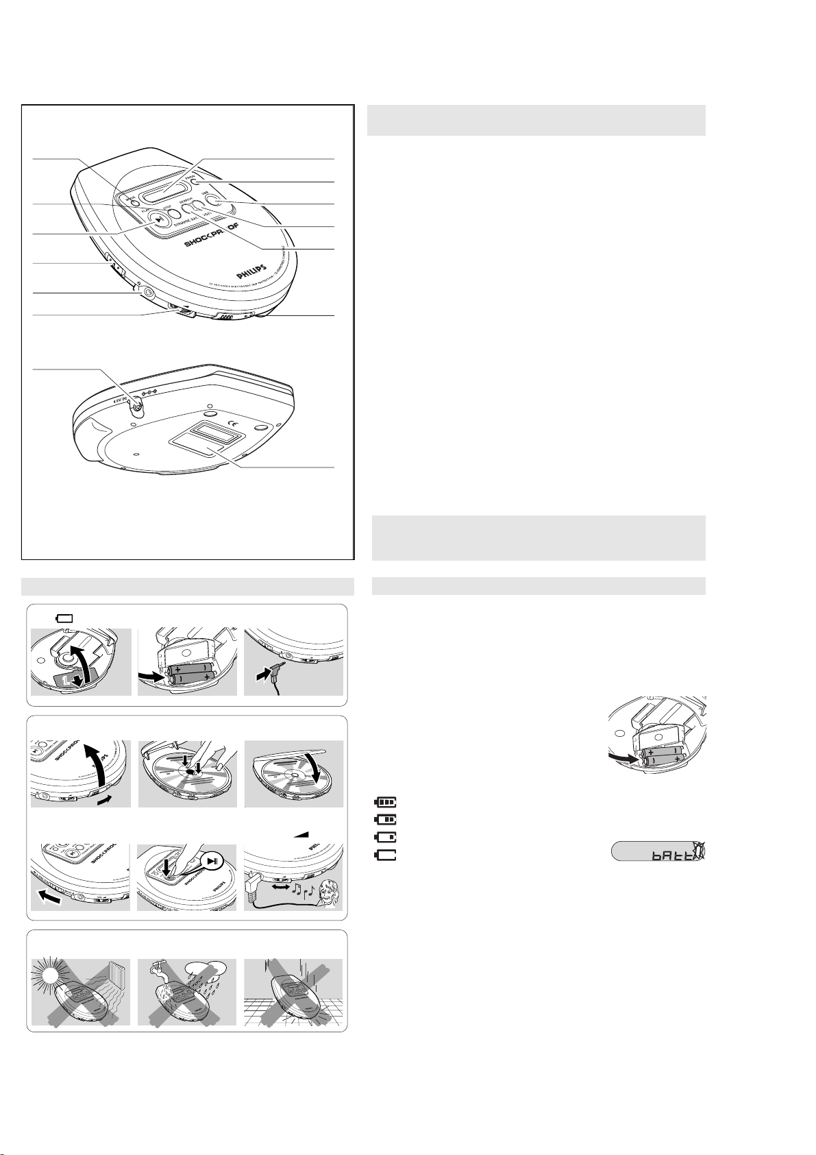
•Do not touch the lens Aof the CD player.
•Do not expose the unit, batteries or CDs to humidity, rain, sand or excessive
heat (caused by heating equipment or direct sunlight).
•You can clean the CD player with a soft, slightly
dampened, lint-free cloth. Do not use any cleaning
agents as they may have a corrosive effect.
•To clean the CD, wipe it in a straight line from the
center toward the edge using a soft, lint-free cloth. A
cleaning agent may damage the disc! Never write on
a CD or attach a sticker to it.
•The lens may cloud over when the unit is moved sud-
denly from cold to warm surroundings. Playing a CD is
not possible then. Leave the CD player in a warm environment until the mois-
ture has evaporated.
•Active mobile phones in the vicinity of the CD player may cause malfunctions.
•Avoid dropping the unit as this may cause damage.
Headphones HE 035
•Connect the supplied headphones to the LINE OUT/p
jack of the player.
Note:
LINE OUT
/
p
can also be used for
connecting this set to your HiFi system.To adjust
the sound and volume, use the controls on the
connected audio equipment and on the CD player.
IMPORTANT!
Hearing safety: Do not play your headphones at a high vol-
ume. Hearing experts advise that continuous use at high volume can permanently dam-
age your hearing.
Traffic safety: Do not use headphones while driving a vehicle. It may create a hazard
and it is illegal in many countries. Even if your headphones are an open-air type
designed to let you hear outside sounds, do not turn up the volume so high that you
cannot hear what is going on around you.
VOL
E
OFF
•
RSUME
•
HOLD
O
UT
L
INE
/
GENERAL INFORMATION / CD PLAY
Only use the AY 3545 (4822 219 10033) or AY 3548 (3140 118 71890) car voltage
converter (4.5 V DC, positive pole to the centre pin) and the AY 3501 car adapter
cassette. Any other product may damage the set.
1Put the set on a horizontal, vibration-free and stable surface. Make sure it is
in a safe place, where the set is neither a danger nor an
obstacle to the driver and the passengers.
2Plug the voltage converter into the
cigarette lighter socket
(only for 12 V car
battery, negative grounding),
then connect
the wired end with 4.5V DC input socket on the
set.
3If necessary, clean the cigarette lighter socket
to obtain a good electrical contact.
4Turn down the volume and connect the cassette
adapter plug to LINE OUT/pon the set.
5Carefully insert the cassette adapter into the car radio’s cassette compartment.
6Make sure the cord does not hinder your driving.
7Decease the volume on the set, if necessary. Start playback on the set and
adjust the sound with the car radio controls.
•
Always remove the voltage converter from the cigarette lighter socket
when the set is not in use.
Note: If your car radio has a LINE IN socket , it is better to use it for the
car radio connection instead of the cassette adapter. Connect the signal
lead to this LINE IN socket and to
LINE OUT/p
on the set.
4,5 V DC
12 V DC
OPE
N
VOL
E
OFF
•
RSUME
•
HOLD
O
UT
L
INE
/
4
4
9
This CD-player can play all kinds of Audio Discs such
as CD-Recordables and CD-Rewritables. Do not try to play a CD-ROM, CDi, VCD,
DVD or computer CD.
1Push the OPEN
2
slider to open the player.
2Insert an audio CD, printed side up, by pressing the
CD onto the hub.
3Close the player by pressing the lid down.
4Press 2; to switch the player on and start playback.
yThe current track number and elapsed playing
time are displayed.
•You can pause playback by pressing 2; .
yThe time at which playback was paused starts
flashing.
•You can continue playback by pressing 2; again.
5Press 9 to stop playback.
yThe total number of tracks and the total playing
time of the CD are displayed.
6Press 9 again to switch the player off.
•To remove the CD, hold it by its edge and press the
hub gently while lifting the CD.
Note: If there is no activity, the set will automatically
switch off after a while to save ener
gy
.
3
OPE
N
VOL
D
O
UT
L
INE
/
4
4
9
E
/
4
4
9
ESP
ESP
0
INSTRUCTION FOR USE

2-3
CD PLAY / FEATURES
•If a CD-Recordable (CD-R) or a CD-Rewritable (CD-RW) is not recorded
properly, nF dISC is displayed, indicating that the CD has not been
finalized. In that case, use FINALIZE on your CD recorder to complete the
recording.
•When playing a CD-Rewritable (CD-RW), please note that it takes 3–15
seconds after pressing 2; for sound reproduction to start.
•Playback will stop if you open the CD lid.
•While the CD is read, 01 --:-- flashes in the display.
Volume and bass
Volume adjustment
•Adjust the volume by using VOL E.
Bass adjustment
•Press DBB to switch the bass enhancement on or
off
yDBB appears if the bass enhancement is
activated.
DBB
FEATURES
You can store up to 30 tracks to play in a program.
A single track may be stored more than once in the
program.
1While playback is stopped, select a track with
∞or §.
2Press PROG to store the track.
yPROG lights up; the track number
programmed and Pwith the total number of
stored tracks are displayed.
3Select and store all desired tracks in this way.
4Press 2; to start playback of your selected tracks.
yPROG is shown and playback starts.
•You can review the program by pressing PROG for
more than 2 seconds.
yThe display shows all the stored tracks in sequence.
Notes: –If you press PROG and there is no track selected,
SELECt
is dis-
played.
–If you try to store more than 30 tracks,
FULL
is displayed.
Clearing the program
•While playback is stopped, press 9 to clear program.
yCLEAr is displayed once, PROG goes off, and the program is cleared.
Note: The program will also be cleared if the power
supply is interrupted, or if the CD-player lid is
opened, or if the set switches off automatically.
4
ESP
PROG
ESP
ESP
PROG
Selecting a track during playback
•Briefly press ∞ or §once or several times to skip to the current, previous or
next track.
yPlayback continues with the selected track, and
the track’s number is displayed.
Selecting a track when playback is stopped
1Briefly press ∞ or §once or several times to select
the desired track. The track number is displayed.
2Press 2; to start CD play.
yPlayback starts with the selected track.
Searching for a passage during playback
1Keep ∞ or §pressed to find a particular passage in
a backward or forward direction.
ySearching starts while playback continues at low
volume. After 2 seconds the search speeds up.
2Release the button when you reach the desired passage.
yPlayback continues from this position.
Notes: –If the player is in SCAN mode (see MODE chapter), searching is not
possible.
–In shuffle, shuffle repeat all or repeat mode (see MODE chapter), or
while playing a program, searching is only possible within the
particular track.
4
4
9
Selecting a track and searching
It is possible to play tracks in random order, to repeat a single track or the entire
CD, and to play the first few seconds of each track.
1Press MODE during playback as often as required in
order to activate one of the following ‘modes’. The
active mode is shown in the display.
ySHUFFLE : All tracks of the CD are played in
random order until all of them have been played
once.
ySHUFFLE REPEAT ALL : All tracks of the CD
are played repeatedly in random order.
yREPEAT : The current track is played repeatedly.
yREPEAT ALL
:
The entire CD is played repeatedly.
ySCAN: The first 10 seconds of each of the remain-
ing tracks are played in sequence.
2Playback starts in the chosen mode after 2 seconds.
•To return to normal playback, press MODE repeatedly until the display shows
no active modes.
ESP
With a conventional portable CD-player you might have experienced that the
music stopped e.g. when you were jogging. The Electronic Skip Protection
prevents loss of sound caused by light vibrations and shocks. Continuous playback
is ensured. However ESP does not prevent playback interruptions during vigorous
running. It also does not protect the unit against any damage caused by dropping!
In this set ESP is default ON. It is possible to set ESP off.
•Press MODE for more than 2 seconds.
y ESP disappears.
•Press MODE again for more than 2 seconds.
y ESP is displayed.
ESP on
➟
ESP off
➟
ESP on
ESP
SHUFFLE
REPEAT ALL
Selecting different playing possibilities-MODE
INSTRUCTION FOR USE

2-4
FEATURES / TROUBLESHOOTING
You can interrupt playback and continue (even after an
extended period of time) from the position where
playback stopped (RESUME) and you can lock all buttons of the set so that no
action will be executed (HOLD). Use the
RESUME–HOLD–OFF slider for these functions.
RESUME –continuing from where you have stopped
1Switch the slider to RESUME during playback to acti-
vate RESUME.
yRESUME is shown.
2Press 9whenever you want to stop playback.
3Press 2; whenever you want to resume playback.
yRESUME is shown and playback continues from
where you have stopped.
•To deactivate RESUME, switch the slider to OFF.
yRESUME goes off.
HOLD –locking all buttons
You can lock the buttons of the set by switching the slider to HOLD. Now, when a
key is pressed, no action will be executed. This is of use, for example, when
transporting the player in a bag. With HOLD activated, you can avoid accidental
activation of other functions.
1Switch the slider to HOLD to activate HOLD.
yAll buttons are locked. HoLd is shown when you press any button. If
the set is switched off, HOLD will be shown
only when 2; is pressed.
2To deactivate HOLD, switch the slider to OFF.
Note: If you deactivate HOLD by switching the slider to RESUME, you will be
activating the RESUME function.
ESP
RESUME
E S P HOLD
WARNING: Under no circumstances should you try to repair the set yourself as
this will invalidate the warranty. If a fault occurs, first check the points listed,
before taking the unit for repair. If you are unable to solve a problem by following
these hints, consult your dealer or service center.
The CD player has no power, or playback does not start
•Check that your batteries are not dead or empty, that they are inserted
correctly, that the contact pins are clean.
•Your adapter connection may be loose. Connect it securely.
•For in-car use, check that the car ignition is on. Also check player’s batteries.
The indication no diSC is displayed
•Check that the CD is clean and correctly inserted (label-side upward).
•If your lens has steamed up, wait a few minutes for this to clear.
The indication nF diSC is displayed
•CD-RW (CD-R) was not recorded properly. Use FINALIZE on your CD-recorder.
The indication HOLD is on and/or there is no reaction to controls
•If HOLD is activated, then deactivate it.
•Electrostatic discharge. Disconnect power or remove batteries for a few seconds.
The CD skips tracks
•The CD is damaged or dirty. Replace or clean the CD.
•RESUME, SHUFFLE or PROGRAM is active. Switch off whichever is on.
No sound or bad sound quality.
•PAUSE might be active. Press 2; .
•Loose, wrong or dirty connections. Check and clean connections.
•Volume might not be appropriately adjusted. Adjust the volume.
•Strong magnetic fields. Check player’s position and connections. Also keep
away from active mobile phones.
•
For in-car use,
check that the cassette adapter is inserted correctly, that the car
cassette player’s playback direction is correct (press autoreverse to change),
and that the cigarette lighter jack is clean. Allow time for temperature change.
Troubleshooting
E
FF
•
RSUME
•HO LD
O
UT
L
INE
/
INSTRUCTION FOR USE

3-1
SERVICE TOOLS
Audio signal disc SBC 429.......................................................................4822 397 30184
Playability test disc SBC 444...................................................................4822 397 30245
Test disc 5 (disc without errors ) +
Test disc 5A (disc with dropout errors, black spots and fingerprints)
SBC 426/426A.....................................................................4822 397 30096
Burn in test disc (65 min. 1kHz signal at -30 dB level without “pause”).....4822 397 30155
Universal test cassette Fe SBC 420........................................................4822 397 30071
anti-static table mat large 1200x650x1.25mm
small 600x650x1.25mm
anti-static wristband
connection box (3 press stud connections, 1MΩ))
extendible cable (2m, 2MΩ,to connect wristband to connection box)
connecting cable (3m, 2MΩ, to connect table mat to connection box)
earth cable (1MΩ, to connect any product to mat or to connection box)
KIT ESD3 (combining all 6 prior products - small table mat)
wristband tester
ESD PROTECTION EQUIPMENT
ACCESSORIES
ACCESSORIES FOR CD-PORTABLE /00C /00Z /00C /00Z
AX2200 AX1101
/05Z
AY3170/00 AC/DC ADAPTOR 4822 219 10617
AY3170/05 AC/DC ADAPTOR 3140 118 33610 X
HE035/77 HEADPHONE 9965 000 11492 X X
X
X
4822 466 10953
4822 466 10958
4822 395 10223
4822 320 11307
4822 320 11305
4822 320 11306
4822 320 11308
4822 310 10671
4822 344 13999

4-1
2V 6
Servo Driver
MM1538XQ
Thomson CD
Mechanism
TPP38
HF/DSP
SAA7824HL TMP86C820U
LCD 4-digits
segment
Keyboard
ESP Control
BU9422KS /
SM5907
DRAM 1Mx16 DC Supply
H/P Jack
BLOCK DIAGRAM - SET

4-2
33
34 22
21
20
19
18
17
16
15
14
13
12
35
36
37
38
39
40
41
42
43
44
1 2 3 4 5 6 7 8 9 10 11
32 31 30 29 28 27 26 25 24 23
AMUTE
EMP
HVcc
PSW
CLK
START
OFF
CHGVcc
SEL
PREGND
PWMFIL
IN1
MUTE2
IN2
MUTE34
IN4
IN3
Vref
VSYS2
OP+
OPOUT
VSYS1
RCHG OUTIR OUT1F OUT2R OUT2F POWGND OUT3F OUT3R OUT4F OUT4R BRAKE1
BSEN BATT RESET DEAD SW EO EI SPRT CTN.C. OP
-
V
I
/
V
I
/
V
I
/
V
I
/
BRAKE1
BTL BTL BTL BTL
POWER
OFF
STARTER
MAXIMUM
DETECTION
CLK
TSD
TRIANGLE WAVE
OVER-VOLTAGE
PRE
-
DRIVER POWER SUPPLY
TSD
POWER UNIT
POWER SUPPLY
CONTROL CIRCUIT
POWER SUPPLY
MUTE2
MUTE34
IC BLOCK DIAGRAM
U1: MM1538XQ

4-3
IC BLOCK DIAGRAM
U4: TMP86C820U

4-4
Fig.2 Pin configuration.
21
22
23
24
29
30
31
32
33
34
35
36
37
38
39
40
MONITOR
SENSE
IREF
VDDA1
VREF_OUT
D1
D2
D3
D4
R1
R2
CSLICE
VDDA2
DAC_LP
DAC_VPOS
BUF_VPOS
BUF_IN_R
BUF_OUT_R
CDT_RDY
CDT_DATA
CDT_CLK
MOTO1
MOTO2
VSSD3
RA
SAA7824
V1
V2
SUB
DATA
RCK
WCLI
V5
V4
SCLI
BUF_OUT_L
LKILL
SL
FO
BUF_IN_L
STATUS
TEST3
SCL
BUF_GND
SCLK
EF
VDDD2
RAB
V3
SILD
VDDD3
RKILL
TEST1
CLK4_12
TEST2
RESET
SDA
LPOWER
EXTFILTER
VSSA1
DAC_RN
DAC_VREF
DAC_LN
WCLK
CLK16
25
26
27
28
80
79
78
77
72
71
70
69
68
67
66
65
64
63
62
61
76
75
74
73
1
2
3
4
9
10
11
12
13
14
15
16
17
18
19
20
5
6
7
8
60
59
58
57
52
51
50
49
48
47
46
45
44
43
42
41
56
55
54
53
OSCOUT
VSSA2
OSCIN
VSSA3
DAC_GND
DAC_RP
CFLAG
VSSD1
SDI
VDDD1
SBSY
SFSY
DOBM
VSSD2
TEST4
LASER
IC BLOCK DIAGRAM
U5: SAA7824HL

4-5
EFM
DEMODULATOR
MICRO
INTERFACE
CONTROL
PART
BIAS
GENERATOR
VREF_OUT
CONTROL FUNCTION
OUTPUT
STAGES
D2 D4 R1 R2
SCL
SDA
CD-TEXT
INTERFACE
TEST
TEST1
TEST2
TIMING
OSCIN
OSCOUT
CLK16
CLK4_12
RA
SL
DIGITAL
PLL
SRAM
RAM
ADDRESSER
SUBCODE
PROCESSOR
SBSY
SFSY
SUB
RCK
STATUS
DECODER
MICRO-
CONTROLLER
INTERFACE
RESET
VERSATILE PINS
INTERFACE KILL
BITSTREAM
DAC
SDI
WCLI
SCLI
SERIAL
DATA
(LOOPBACK)
INTERFACE
EF
DATA
WCLK
SCLK
SERIAL
DATA
INTERFACE
PEAK
DETECT
EBU
INTERFACE
AUDIO
PROCESSOR
ERROR
CORRECTOR
FLAGS
MOTOR
CONTROL
DOBM
CFLG
MOTO1
MOTO2
V1 V2 V3 V5 RKILL
SILD
RAB
V4
D1 D3
HFPASS FILTER
DATA SLICER &
THRESHOLD CON-
TROL
IREF
MONITOR
LASER
MONITOR
ADC LASER
LASER
POWER CON-
TROL LOGIC
LKILL
INTERFACE
CONTROL
SENSE LPOWER
EXTFILTER
DC OFFSET COMPENSATION
VOLTAGE & CURRENT
BUFFER
HF & LF CAPTURE
D1-D4
SUM
ANTI ALIAS
DSIC ADC
TEST3
TEST4
CDT_RDY
CDT_DATA
CDT_CLK
DAC_VPO
DAC_RP
DAC_RN
DAC_LP
DAC_LN
DAC_VREF
DAC_GND
BUF_IN_R
BUF_IN_L
BUF_OUT_R
BUF_OUT_L
BUF_VPOS
BUF_GND
CSLICE
FO
HEADPHONE
BUFFERS
IC BLOCK DIAGRAM
U5: SAA7824HL

4-6
IC BLOCK DIAGRAM
U6: SM5907AF

5-15-1
FIT FOR Tuner
NO FIT
NO FIT
RESUME
RESUME
OFF
C0
S10
S11
S11
C2
S2
S8
S7
C1
S0
KEY2
C1
S1
S4
KEY2
S6
KEY1
S4
S8
C2
S1
S5
S9
S13
S0
S3
S9
S5
S3
S6
C3
C3
S12
S2
S7
S10
C0
S12
S13
HOLD
HOLD
S14
KEY1
PLAY
FM
S14
PLAY
FM
FM
PLAY
S[0..13]
+AVDD+VR
+VR
+VR
+VR
+AVDD
+AVDD
+AVDD
+VR
+VR
+VR
+Vb
R142 1K
R8
100K
R64 1K
R69 1K
C99
6p*
R65 1K
C100
6p*
R68 1K
Q11
BC847B
J2
JST 26FMN-SMT-A-TF
JST 26FMN-SMT-A-TF
1
2
3
4
5
6
7
8
9
10
11
12
13
14
15
16
17
18
19
20
21
22
23
24
25
26
R32
33K
R67 1K
R106
100E
R66 1K
S602
SW SPTT
4
2
3
1
R125
10K
Q10
BAW56*
BAW56*
R63 1K
C95
100n
R113
220K
R30
22K
R151 470K
R98 10E
R119
220K
R31
33K
R150 470K
R110
10K*
R103
100K
R130
10K C27
10n
R97
R97
100K
R77 100E
R109
10K*
R105
100K
TP24
R51 1K
R140
220K
R29
22K
R75 100E
R52 2K2
C75
10u
C96
2u2
R53 2K2
TP23
XT603
4.19MHz
4.19MHz
R54 2K2
R111
10E
U4
TMP86C820U
TMP86C820U
1
2
3
4
5
6
7
8
9
10
11
12
13
14
15
16
17
18
19
20
21
22
23
24
25
26
27
28
29
30
31
32
33
34
35
36
37
38
39
40
41
42
43
44
45
46
47
48
49
50
51
52
53
54
55
56
57
58
59
60
61
62
63
64
VSS
XIN
XOUT
TEST
VDD
P21/XTIN
P22/XTOUT
/RESET
P20
P60
P61
P62
P63
P64
P65
P66
P67
VAREF
AVDD
P10/SEG31
P11/SEG30
P12/SEG29
P13/SEG28
P14/SEG27
P15/SEG26
P16/SEG25
P17/SEG24
P50/SEG23
P51/SEG22
P52/SEG21
P53/SEG20
P54/
SEG19
P55/SEG18
P56/SEG17
P57/SEG15
P70/SEG15
P71/SEG14
P72/SEG13
P73/SEG12
P73/SEG11
P74/SEG10
P76/SEG9
P77/SEG8
SEG7
SEG6
SEG5
SEG4
SEG3
SEG2
SEG1
SEG0
COM3
COM3
COM2
COM2
COM1
COM1
COM0
COM0
V3
V2
V1
C1
C0
P30
P31
P32
P33
R55 2K2
R124
100E
R56 1K
C103
100n
R57 1K
C106
47n
C32 470n
R112
1M
R94
1K
R70 1K
R58 1K
C102
10u
C114*
1u
XT604
DT-28 32.768KHz*
R59 1K
1KR92
C113
1u
R107
1M
R60 1K
R90 1K
R71 0E
R61 1K
Q19
BAW56
BAW56
R62 1K
R108 1M
YMCLK
YMDATA
RADIO-SCL
RADIO-SDA
SLEEP
YMLD
SILD
SFSY
DC_IN
BEEP
/PORES
RADIO-BUSEN
ZRESET
BATT_LEVEL
MUTE34
RAB
DM
DBB_ON
MO/ST
AMUTE
WAKE
WAKE
DOOR
POWER-CD
POWER-CD
CIRCUIT DIAGRAM - CONTROL PART

5-2 5-2
FIT FOR TUNER VERSION
NOT FIT
NOT FIT
NOT FIT FOR TUNER VERSION
SLE+
MOT
MOT
-
HOMESW
HOMESW
MOT+
MOT+
SLE-
2V6D
2V6D
2V6A
2V6D
+VR
2V6A_RADIO
2V6D_RADIO
+VR
+VR
2V6D
+Vb
+V_HEADPHONE
+VR
+VR
L4
2.2uH
R162
33K 1%
R44 2K2
R39 2K2
D3
BAS316
+
C617
100u
C36
100n
TP
TP
15
+
C608
47u LOW ESR
+
C618
220u
L6*
2.2uH
C31 1u
C48
1n5*
Q6* BSH205
R36 2K2
R35
100K
TP13
C5 1u
R4
10E
R24*
100E
L602 33uH
R10 47E
C24 120n
TP12
Q18*
BC817-40
C33 470p
TP11
C39
100n*
D1
PRLL5817
C64
470n
TP34
R116
2E2
TP10
C7
1n
C20 1n
R184K7
TP8
C37
100n*
R141
0E
C52
3n3
C53
3n3
TP6
R22*
100K
R28 5K6
R14 100E
TP3
TP3
C26
470n
TP9
R11
3.9K
R33 5K6
C49
1n5*
L11
2.2uH
TP7
C42
100n
R50*
47K
TP1
R166
220K*
+
C609
220u
R40 2K2
R45
100K 1%
C6
47p
R37 2K2
R23*
100E
C13
470n*
C30 3n3
+
C628*
100u
Q12
BSH205*
TP5
TP5
Q3* BSH205
R27 51K
R9
100K
L601
L100uH+6uH Q1
PBS5140T
R46
100K 1%
R47
100K
R21 22K
L12*
2.2uH
U1
MM1538
MM1538
XQ
1
2
3
4
5
6
7
8
9
10
11
12
13
14
15
16
17
18
19
20
21
22
23
24
25
26
27
28
29
30
31
32
33
34
35
36
37
38
39
40
41
42
43
44
BSEN
BATT
RESET
DEAD
SW
EO
EI
SPRT
CT
N.C
OP-
VSYS1
OPOUT
OP+
VSYS2
Vref
IN3
IN3
IN4
IN4
MUTE34
IN2
IN2
MUTE2
IN1
IN1
BRAKE1
OYT4R
OUT4F
OUT3R
OUT3R
OUT3F
POWGND
OUT2F
OUT2R
OUT2R
OUT1F
OUT1R
OUT1R
RCHG
AMUTE
EMP
HVCC
PSW
CLK
START
OFF
CHGVCC
CHGVCC
SEL
PREGND
PWMFIL
PWMFIL
C51
3n3
BT601
BATTERY 2.4V
TP2
TP2
Q4
BSH105
R149 5K6
D2
PRLL5817
MX601
JST ZH-6A
JST ZH-6A
1
2
3
4
5
6
D9
PRLL5817
C43
10n
C50
3n3*
R43 2K2
R167
0E/2E2*
R2 10K
D10
PRLL5817
Q2
PBS4140T
S601
ALPS SPPB51
F601 SP 63
C44
100n
R1 10K
R7
1K
C28
470n
J601
TC18-099-03
R5
47K
C69*
470n
C4
100n
C38
100n*
R163
33K 1%
SLE+
RAD+
MOTO
DOOR
MOT
MOT
-
SLE+
HOME_SW
HOME_SW
DC_IN
MOT+
MOT+
RA
RAD-
SLE-
SLEEP
SLE-
FOC+
MOT+
MUTE34
MOT-
SL
FO
FOC-
WAKE
BATT_LEVEL
DM
POWER-CD
CIRCUIT DIAGRAM - SUPPLY AND SERVO PART

5-35-3
R1 VF
R1 VF
VREF
VREF
CD18 PHONIC
CD18 PHONIC
D3 VC
D3 VC
LASER ON
LASER ON
R2 VE
R2 VE
D2 VB
D2 VB
D1 VA
D1 VA
VDDA
VDDA
D4 VD
D4 VD
TPP33B
TPP33B
PICK-UP
PICK-UP
Mechanism
Mechanism
THOMSON
THOMSON
NOT FIT
NOT FIT
No Fit
No Fit
NO FIT
NO FIT
D1
D1
+V_SUBS
+V_SUBS
L
D4
D4
VCC_1/2
VCC_1/2
R1
R1
DD1
DD1
A3
A3
A1
A1
A2
A2
NCAS
NCAS
NCAS
NCAS
A8
A8
A8
A8
A6
A6
A0
A0
DD2
DD2
A3
A3
NWE
NWE
A9
A9
DD2
DD2
NWE
NWE
A10
A10
A4
A4
A5
A5
A4
A4
DD1
DD1
DD0
DD0
A1
A1
A7
A7
DD3
DD3
A6
A6
DD0
DD0
A5
A5
A2
A2
A10
A10
NRAS
NRAS
A[0..10]
A[0..10]
NRAS
NRAS
A0
A0
DD3
DD3
A7
A7
A9
A9
R
RAD-
RAD-
MD_IN
MD_IN
RAD+
RAD+
D3
D3
FOC+
FOC+
FOC-
FOC-
D2
D2
GND-A
GND-A
LD_IN
LD_IN
VR_IN
VR_IN
R2
R2
2V6A
2V6A
2V6A
2V6A
2V6D
2V6D
+VR
+VR
2V6D
2V6D
2V6D
2V6D
2V6A
2V6A
+V_HEADPHONE
+V_HEADPHONE
2V6D
2V6D
2V6D
2V6D
2V6D
2V6D
+VR
+VR
TP22
R89
R89
1K
L9 FB
R114
R114
0E
0E
R155
R155
470R
470R
R153
R153
470R
470R
R87
R87
22K
22K
C84
C84
22n
C68
C68
100n
100n
+
C685
C685
220u
220u
R72
R72
15K
15K
+
C692
C692
470u
470u
R88
R88
22K
22K
C86
C86
100n
100n
C101
C101
100n
100n
C73
C73
10p*
10p*
+
C694
C694
470u
470u
R93
R93
1K
C91
C91
100p
100p
D5
D5
BAS316
BAS316
C14
C14
470n
470n
C16
C16
100n
100n
C115
C115
100n
100n
R81
R81
0E
C19
C19
100n
100n
C108
C108
100n
100n
R165
R165
0E
R157
R157
470R
470R
+
C669
C669
47u
C116
C116
100p
100p
R146
R146
22K
22K
TP27
TP27
C77
C77
100n
R164
R164
0E
C107
C107
100n
100n
C35
C35
22p
22p
C78
C78
100n
100n
R115
R115
0E
0E
R161
R161
470R
TP25
TP25
R131
R131
10K
10K
R79
R79
1E
R118
R118
0E
0E
R126
R126
100K*
100K*
MSM51V17405D/DSL-60SJ
U7
U7
1
2
3
4
5
6
7
8
9
10
11
12
13 14
15
16
17
18
19
20
21
22
23
24
25
26
VCC
VCC
DQ1
DQ1
DQ2
DQ2
/WE
/WE
/RAS
/RAS
NC
NC
NC
NC
A10
A10
A0
A0
A1
A1
A2
A2
A3
A3
VCC
VCC
VSS
VSS
A4
A4
A5
A5
A6
A6
A7
A7
A8
A8
NC
NC
A9
A9
/OE
/OE
/CAS
/CAS
DQ3
DQ3
DQ4
DQ4
VSS
VSS
R160
R160
470R
470R
TP28
TP28
Q16
Q16
BC817-40
BC817-40
L10 FB
C80
C80
22n
22n
R158
R158
470R
470R
TP26
TP26
R132
R132
3.3K
3.3K
R156
R156
470R
470R
+
C667
C667
47u
47u
+
C681
C681
10u
10u
C82
C82
100n
100n
R159
R159
470R
470R
TP29
TP29
C45
C45
22p
22p
C104
C104
1n
1n
R80
R80
10E
Q13
Q13
BC817-40
BC817-40
R147
R147
10K
10K
R91
R91
24K
C72
C72
47n
47n
TP32
R136
R136
10K
10K
+
C671
C671
100u
100u
+
C690
C690
100u
100u
TP35
TP35
R73
R73
10E
TP33
TP33
R133
R133
10K
10K
+
C689
C689
100u
100u
R144
R144
10K
TP36
U6
U6
SM5907AF
SM5907AF
1
2
3
4
5
6
7
8
9
10
11
12
12
13
13
14
14
15
15
16
16
17
17
18
18
19
19
20
20
21
21
22
22
23
24
25
26
27
28
29
30
31
32
33
34
34
35
35
36
36
37
37
38
38
39
39
40
40
41
41
42
42
43
43
44
44
VDD2
VDD2
UC1
UC1
UC2
UC2
UC3
UC3
UC4
UC4
UC5
UC5
NCAS3
NCAS3
NTEST
NTEST
CLK
CLK
VSS
VSS
YSRDATA
YSRDATA
YLRCK
YLRCK
YSCK
YSCK
ZSCK
ZSCK
ZLRCK
ZLRCK
ZSRDATA
ZSRDATA
YFLAG
YFLAG
YFCLK
YFCLK
YBLKCK
YBLKCK
NRESET
NRESET
ZSENSE
ZSENSE
VDD1
VDD1
YDMUTE
YDMUTE
YMLD
YMLD
YMDATA
YMDATA
YMCLK
YMCLK
A10/NCAS2
A10/NCAS2
NCAS
NCAS
D2
D2
D3
D3
D0
D0
D1
D1
NWE
NWE
NRAS
NRAS
A9
A9
A8
A8
A7
A7
A6
A6
A5
A5
A4
A4
A0
A0
A1
A1
A2
A2
A3
A3
Q9
Q9
BC847B
BC847B
C109
C109
1u*
1u*
R104
R104
91E
91E
R135
R135
10K
TP31
TP31
R134
R134
3.3K
Q22
Q22
BC817-40
BC817-40
R96
R96
1K
Q15
Q15
BC817-40
BC817-40
C105
C105
1n
1n
R48
R48
10E
L1
BEAD
BEAD
Q23
Q23
BC817-40
BC817-40
R95
R95
100E
100E
U5
SAA7824HL
SAA7824HL
1
2
3
4
5
6
7
8
9
10
11
12
13
14
15
16
17
18
19
20
21
22
23
24
25
26
27
28
29
30
31
32
33
34
35
36
37
38
39
40
41
42
43
44
45
46
47
48
49
50
51
52
53
54
55
56
57
58
59
60
61
62
63
64
65
66
67
68
69
70
71
72
73
74
75
76
77
78
79
80
LPWR
LPWR
EXTF
EXTF
MONITOR
MONITOR
SENSE
SENSE
VSSA1
VSSA1
IREF
IREF
VDDA1
VDDA1
VRFO
VRFO
D1
D2
D3
D4
R1
R2
CEQ
CEQ
VDDA2
VDDA2
VSSA2
VSSA2
OSCO
OSCO
OSCIN
OSCIN
VSSA3
VSSA3
DAG
DAG
DARP
DARP
DARN
DARN
DAREF
DAREF
DALN
DALN
DALP
DALP
DAVP
DAVP
BUVP
BUVP
BUIR
BUIR
BUOR
BUOR
BUOL
BUOL
BUIL
BUIL
BUGND
BUGND
LKILL
LKILL
RKILL
RKILL
CRDY
CRDY
CDAT
CDAT
CCLK
CCLK
CFLG
CFLG
VSSD
VSSD
VDDD
VDDD
SDI
SDI
WCLI
WCLI
SCLI
SCLI
EF
EF
DATA
DATA
WCLK
WCLK
SCLK
SCLK
CLK16
CLK16
CLK12
CLK12
RESET
RESET
SDA
SDA
SCL
SCL
RAB
RAB
SILD
SILD
STATUS
STATUS
RCK
RCK
SUB
SUB
SFSY
SFSY
SBSY
SBSY
VSD2
VSD2
DOBM
DOBM
VDD1
VDD1
RA
RA
FO
SL
SL
MOTO1
MOTO1
MOTO2
MOTO2
VSD3
VSD3
VDD2
VDD2
V1
V1
V2
V2
V3
V3
V4
V4
V5
V5
TEST1
TEST1
TEST2
TEST2
TEST3
TEST3
TEST4
TEST4
LASE
LASE
Q14
Q14
BC817-40
BC817-40
C97
C97
10n
MX602
602
JST 16FMN-STK-A
JST 16FMN-STK-A
1
2
3
4
5
6
7
8
9
10
11
12
13
14
15
16
R99
R99
1K
R74
R74
2E2
2E2
C79
C79
10u
L8 FB
R148
R148
0E/Fit for no ESP
0E/Fit for no ESP
C66
C66
100n
100n
R127
R127
100K*
100K*
R123
R123
1K
J603
J603
TC38-165-02
TC38-165-02
2
1
3
TP21
R137
R137
10E
R122
R122
1K
+
C688
C688
100u
100u
R120
R120
1K
1K
Q17
Q17
BC817-40
BC817-40
TP20
R138
R138
10E
10E
C70
C70
100n
100n
VR601
VR601
F-1001G-3 C200K
F-1001G-3 C200K
R145
R145
100K
100K
C18
C18
270p
270p
TP19
R121
R121
1K
1K
Q8
Q8
BC817-40
BC817-40
C65
C65
100n
C83
C83
100n
C9
C9
270p
270p
C93
C93
100p
100p
TP18
Q21
Q21
BAW56
BAW56
3
1
2
R102
R102
0E
0E
R100
R100
3K3
3K3
R117
R117
100E
100E
R78
R78
10E
R128
R128
47K
47K
C8
C8
270p
270p
R154
R154
470R
470R
R84
R84
22K
22K
XT
XT
602
602
CSTLS 8.4672MHz
CSTLS 8.4672MHz
C76
C76
100n
100n
R101
R101
0E
0E
R129
R129
47K
47K
R76
R76
10E
10E
R85
R85
22K
22K
+
C687
C687
220u
220u
+
C718
C718
100u
12
C98
C98
10n
10n
R83
R83
10K
R152
R152
470R
470R
R86
R86
22K
22K
+
C717
C717
100u
12
R82
R82
18E
18E
R49
R49
1K
YMDATA
YMDATA
RAB
RAB
SFSY
SFSY
/PORES
/PORES
BEEP
BEEP
YBLKCK
YBLKCK
SL
SL
CLK_16
CLK_16
ZLRCK
ZLRCK
YSCK
YSCK
YSRDATA
YSRDATA
YLRCK
YLRCK
YMCLK
YMCLK
YFLAG
YFLAG
DBB_ON
DBB_ON
SILD
SILD
ZSRDATA
ZSRDATA
ZSCK
ZSCK
MOTO
MOTO
HOME_SW
HOME_SW
AUDIO-R
AUDIO-R
FM-ANT
FM-ANT
FO
RA
RA
ZRESET
ZRESET
YSRDATA
YSRDATA
ZLRCK
ZLRCK
YFLAG
YFLAG
YBLKCK
YBLKCK
ZSCK
ZSCK
ZSRDATA
ZSRDATA
CLK_16
CLK_16
YLRCK
YLRCK
YSCK
YSCK
RAD+
RAD+
FOC-
FOC-
FOC+
FOC+
RAD-
RAD-
YMDATA
YMDATA
YMCLK
YMCLK
YMLD
YMLD
AMU
AMU
TE
AUDIO-L
AUDIO-L
CDaudio-L
CDaudio-L
CDaudio-R
CDaudio-R
AUDIO-R
AUDIO-R
AUDIO-L
AUDIO-L
CDaudio-L
CDaudio-L
CDaudio-R
CDaudio-R
CIRCUIT DIAGRAM - CD AND AUDIO PART

5-4 5-4
LAYOUT DIAGRAM - component side

5-55-5
LAYOUT DIAGRAM - copper side

6-1 6-1
MOLEXA CON26
R507 0R*
FIT FOR MPC420
2
3
4
5
6
7
8
9
10
11
12
13
14
15
16
17
18
19
20
21
22
23
24
25
26
1
S15
S14
S13
S12
S11
S10
S9
S8
S7
S6
S5
S4
S3
S2
S1
C4
C3
C2
C1
PLAY
VDD
FM
VOUT1
VOUT2
K508
FM*
K502
PLAY
K507
PROG
K501
MODE
K506
DBB
K505
NEXT
K504
PREV
K503
STOP
FIT FOR MPC420
R506 6K8
LCD501
R505 3K3 R504 10K
R503 6K8 R502 3K3 R501 10K
1
2
3
4
5
6
7
8
9
10
11
12
13
14
15
16
17
18
19
CIRCUIT DIAGRAM - KEY BOARD
LAYOUT DIAGRAM - KEY BOARD
This manual suits for next models
1
Table of contents
Other Philips Portable CD Player manuals