DDeessccrriippttiioonn PPaaggee
Revision List.....................................………. 2
Important Safety Notice................................ 3
Warning/Caution/Notice of PANEL .............. 4
Technical Specification................................. 8
Connecting the PDP...................................... 14
Input interfaces.............................................. 18
Top Key and Remote control ........................
19
OSD Tree .......................................... .......... .. 21
OSD operation ...................... ...................... . 24
Trouble shooting .... ................. ................... 44
Repair flow chart ............ .................. .......... . 46
White-Balance adjustment ............. ............. . 51
Software upgrade ........................................ 53
Function block diagram ............................... 55
Waveform of signals .................................... 60
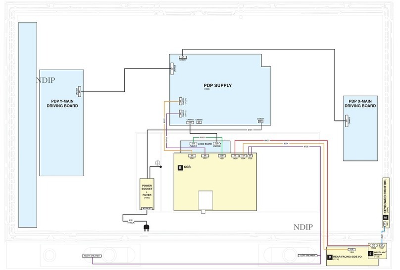
Wiring diagram............................................. 62
Mechanical Instructions................................ 63
Disassembly and assembly ......................... 68
Definition of pixel defects ............................ 72
Block diagram ............................ ................. 75
UART diagram........................... ................. 81
Analog I/O diagram ................... ................. 82
Audio diagram ........................... ................. 83
Supply+RS232 diagram............. ................. 85
DC/DC diagram........................... ................. 86
Video-DAC diagram...................................... . 87
DDeessccrriippttiioonn PPaaggee
Display interface dia
ram.............................
88
PNX2015 supply diagram............................. . 89
PNX2015 standby&control diagram.............. 90
PNX2015 DDR interface diagram................. . 91
PNX2015 Tunnelbus diagram....................... . 92
PNX2015 DV I/O diagram............................. . 93
PNX2015 Audio/Video dia
ram..................... 94
Miscellaneous diagram.................................
95
EEPROM diagram..... ............ ............ ............ . 96
VIPER supply diagram.................................. . 97
A/V+Tunnelbus dia
ram................................ 98
Main Memory diagram.................................. . 99
Control diagram............................................. 100
HDMI I/O+control diagram............................ 101
HDMI + supply diagram................................ 102
Main Tuner diagram...................................... 103
Channel decoder diagram............................
104
Audio amplifier diagram................................
105
Audio Source Selection diagram.................. 106
IF + SAW filter diagram................................ 107
MPIF main supply diagram........ .................. 108
Video source selection diagram .................. 109
PDC diagram............................. .................. 110
Audio output diagram................................... 111
Side AV diagram.......................................... 112
Key control diagram..................................... 113
DDeessccrriippttiioonnPPaaggee
IR diagr am.. .... .. .. .. .. .. .. .. ... .... .. .. .. .. .. . .. ... .... .. .. . 114
OFPC diagra m.... .. .. .. .. .. .. .. .. .. .. .. .. .. .. .. ... .... .. .. . 115
AC filter diag ram.. ..... .. .. .. .... .. .. .. .. .. .. .. ... .... .. .. .. 116
US B filter dia gram... .. .. .. .. .... .. .. .. .. .. .. .. ... .... .. .. .. 117
Image b oard PC B... .. .. .. ... ... .. .. .. .. .. .. .. ... .... .. .. .. 118
Power bo ard PC B... .. .. .. ... ... .. .. .. .. .. .. .. ... .... .. .. .. 120
OFPC PC B .. ... .. .. .. .. .. .. .. ... .... .. .. .. .. .. .. .. ... .... .. .. . 121
AC filter bo ard PC B... .. .. .. ... .. .. .. .. .. .. .. ... .... .. .. ..
122
US B board P C B.... .. .. .. .. ... .... .. .. .. .. .. .. .. ... .... .. .. 123
Side AV bo ard PC B... .. .. .. ... .. .. .. .. .. .. .. ... .... .. .. ..
124
Audio output board /Key board PC B. .. .. ... .. .. .. 125
IR bo ard PC B... .. .. .. .. .. ... .. ... .. . .. .. .. .. .. ... .... .. .. .. . 126
Recommend ed par ts lis t..... .. .. . .. .. .. .. ... .... .. .. .
127
Complete p arts list …… ………………………
Different par t lis t.... .. .. .. .. .. .... .. .. .. .. .. .. .. ... .... .. .. . TBD
Published by JH 667 TV Service Printed in the Netherlands Subject to modification EN 3122 785 16590
©
Copyright 2006 Philips Consumer Electronics B.V. Eindhoven, The Netherlands.
All rights reserved. No part of this publication may be reproduced, stored in a
retrieval system or transmitted, in any form or by any means, electronic,
mechanical, photocopying, or otherwise without the prior permission of Philips.
Colour Television Chassis

