INTRODUCTION
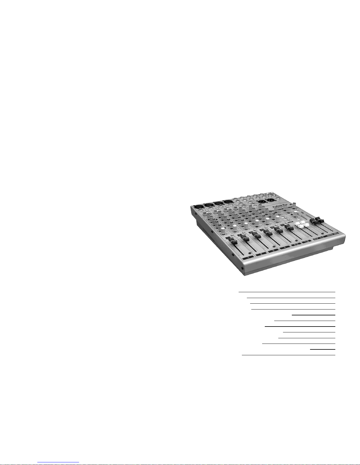
The Podium Pro Audio MX1204 audio mixing console brings premium quality
audio processing circuitry into the compact desktop class of mixers. Carefully
designed signal routing, phantom microphone power, fully balanced design and
versatile effects loops allow this console to provide un-matched performance
and flexibility. Used in accordance with the information provided in this manual,
this product will give years of trouble free use.
MX1204 FEATURES
Four studio grade “Invisible” ultra low noise microphone (MIC)
Preamps
Four balanced line inputs
Direct-coupled signal processing.
Internal “switch-mode” power supply allows operation on 100 to
240VAC
Rugged steel construction provides superior noise shielding.
BEFORE YOU BEGIN
Read and follow these instructions.
Heed all warnings.
Do not use where the mixer may get wet.
Do not obstruct airflow through the ventilation slots.
Never defeat the AC polarizing or safety ground on the AC cord.
Be certain all equipment is OFF before making or breaking
connections.
Clean console only with a damp (not wet) cloth.
Refer all service needs to qualified personnel. There are no user
serviceable components inside.
USING THIS MANUAL
Having a basic understanding of what a mixing console does is very important. This
manual breaks the console down into basic function “blocks”. Details of all controls and
connections are provided for each block.
ABOUT THE MX1204 BLOCK DIAGRAM
To get the most out of your MX1204 mixer, you will need a thorough understanding of
what the console is doing. To help you, a block diagram of the circuitry has been
provided on pages 6 and 7. A block diagram is a simplified schematic which illustrates
signal flow from input to output and shows the numerous routing variations possible.
Throughout this manual, you will frequently see the opamp symbol. . .
h
This indicates that the current topic may be better understood by reviewing the block
diagram.
2
SPECIFICATIONS
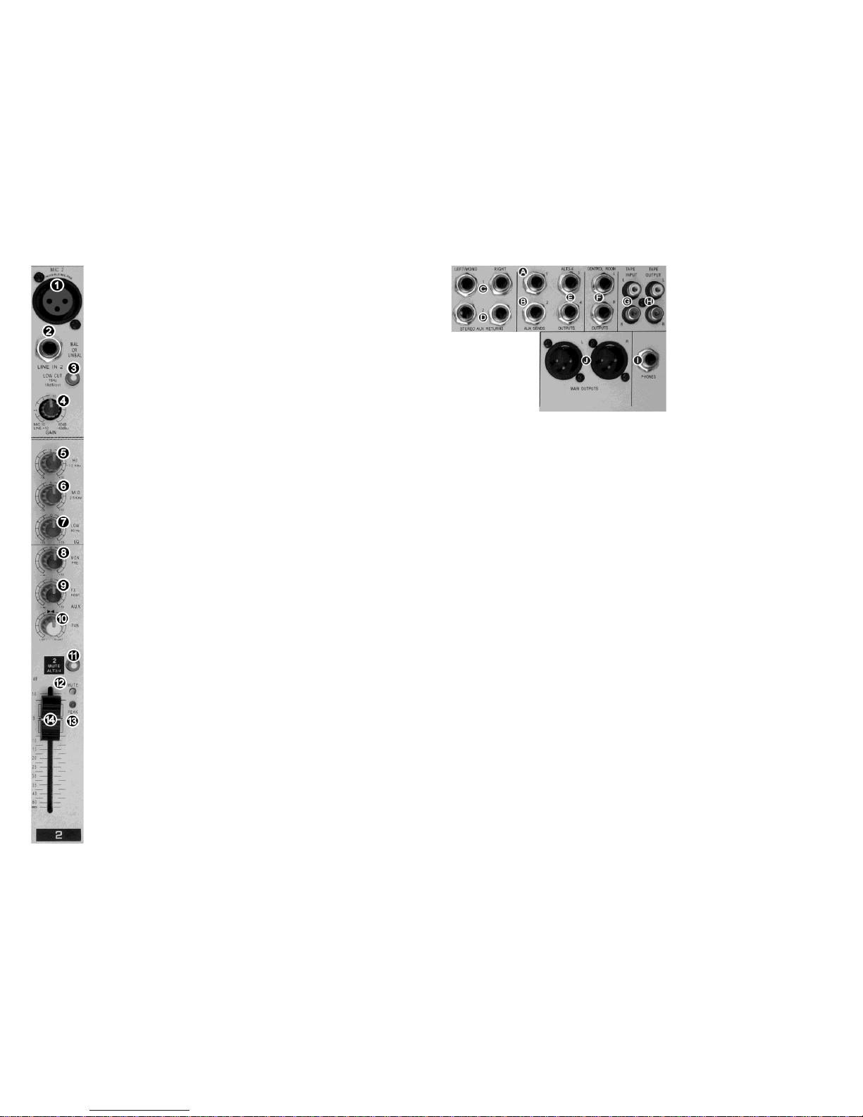
MICROPHONE INPUTS: Balanced XLR. PIN 1: ground, PIN 2: (+), PIN 3: (-)
Frequency Response: (+0dB/-1dB) <20Hz to 40kHz
(+0dB/-3dB) <20Hz to 100kHz
Gain: Adjustable, +10dB to +60dB
Maximum Input Level: (gain set to +10dB) +12dBu
Input Impedance: ≈2.6kΩ (balanced)
Signal-to-Noise ratio: (Re. 0dBu in @ +22dB gain) 110dB (112dB A-weighted)
Equivalent Input Noise: (20Hz to 20kHz)
Source impedance = 0Ω: -134dB (135.7dB A-weighted)
Source impedance = 50Ω: -131dB (133.3dB A-weighted)
Source impedance = 150Ω: -129dB (130.5dB A-weighted)
Distortion: (THD+N) 0.005%/0.004% A-weighted
MONO LINE INPUTS: Balanced ¼” phone jack. TIP: (+), RING: (-), SLEEVE: ground
Frequency Response: (+0dB/-1dB) <10Hz to 90kHz
(+0dB/-3dB) <10Hz to 160kHz
Input impedance: ≈20kΩ (balanced), ≈10kΩ (unbalanced)
Gain Range: -10dB +40dB
Maximum Input Level: +30dBu
Channel-to-Channel Crosstalk: Main faders closed: -90dB, reference level 0dBu
Channel faders closed: -89dB, reference level 0dBu
Channels muted: -89.5dB, reference level 0dBu
1kHz sine wave applied, measurement band pass 20Hz–20kHz.
STEREO INPUTS: Balanced ¼” phone jacks. TIP: (+), RING: (-), SLEEVE: ground
Input impedance: ≈20kΩ (balanced)
Maximum input level: +22dBu
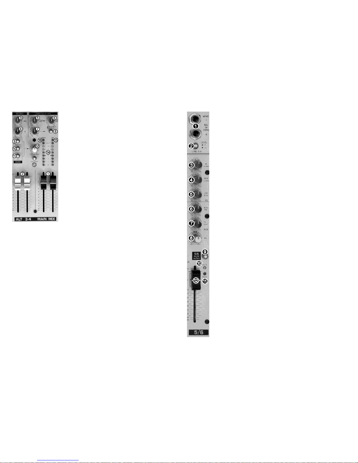
ALL EQUALIZERS
LOW: ± 15dB @ 80Hz, shelving, MID: ± 15dB @ 2.5kHz, HI: ± 15dB @ 12kHz, shelving
AUX SENDS: Unbalanced ¼” phone jacks. TIP: (+), SLEEVE: ground
Output impedance: ≈120Ω
Maximum output level: +22dBu
STEREO AUX RETURNS: Balanced ¼” phone jacks. TIP: (+), RING: (-), SLEEVE: ground
Input impedance: 20kΩ (balanced)
Maximum input level: +22dBu
MAIN OUTPUTS: Balanced XLR, PIN 1: ground, PIN 2: (+), PIN 3: (-)
Output impedance: ≈240Ω (balanced) ≈120Ω (unbalanced)
Nominal output level: +4dBu. Maximum output level: +28dBu
CONTROL ROOM OUTPUTS: Unbalanced ¼” phone jacks. TIP: (+), SLEEVE: ground
Output impedance: ≈120Ω (unbalanced)
Maximum output level: +22dBu
HEADPHONES OUTPUT: Unbalanced ¼” phone jack. TIP: Left, RING: Right, SLEEVE: ground
Output impedance: ≈120Ω (unbalanced)
Maximum output level: +19dBu into 150Ω (+25dBm)
MAIN MIX SYSTEM NOISE:
Main mix @ ∞, channel fader @ ∞: -105dB/-108dB (A-weighted) reference level +6dBu
Main mix @ ∞, channel fader @ 0 dB: -95dB/-97dB (A-weighted) reference level +6dBu
Main mix @ 0 dB, channel fader @ 0 dB: -82.5dB/-85dB (A-weighted) reference level +6dBu
Measured at MAIN OUT. Measurement band pass 20Hz –20kHz. Channels 1-4 @ unitygain, all EQs
flat, all channels on MAIN MIX. Channels 1/3 balance full CCW. Channels 2/4 balance full CW.
POWER CONSUMPTION: 100-240VAC, 40W, Fuse: T1.6AH
DIMENSIONS: H=97mm (3-7/8”) W=247mm (9-11/16”) D=328mm (13”). 2.56kg (5-5/8 lbs)
11