Portech MV-370 User manual

MV-370
Mobile VoIP
(Mar., 2007 Edition)
User’s Manual
PORTech Communications Inc.

【Content】
1. INTRODUCTION ................................................................................................................ 1
2. FUNCTIONS ........................................................................................................................ 1
3. THE CONTENTS IN PACKAGE ...................................................................................... 2
4. DIMENSION AND PANEL DESCRIPTION ................................................................... 3
5. ACCESSORY ATTACHMENT ......................................................................................... 4
6. SETTING AND MANAGING VIA WEB PAGE.............................................................. 4
7. SYSTEM INFORMATION................................................................................................. 5
. ROUTE.................................................................................................................................. 6
9. MOBILE ............................................................................................................................. 12
10. NETWORK....................................................................................................................... 15
12. NAT TRANS ..................................................................................................................... 26
13.SYSTEM AUTH. ............................................................................................................... 27
14.SAVE CHANGE................................................................................................................ 2
15.UPDATE ............................................................................................................................ 29
16.REBOOT............................................................................................................................ 31
17. SETTING AND CHECKING VIA IVR......................................................................... 32
1 .SPECIFICATION ............................................................................................................. 34
19. APPLICATIONS.............................................................................................................. 35
20. SIMPLE STEPS ............................................................................................................... 36
21. APPENDIX: SETUP MV-370 WITH ASTERISK ................................... 37

-1-
1. Introduction
MO ILE VOIP (MV) series products provide you the best
connect solution for heterogeneous network(including:WLAN、
GSM or PSTN)You may use a SIP-protocol VoIP phone or software
to connect to the MO ILE VOIP, then reach this call to the mobile
network, and vice versa. With multiple sets of MO ILE VOIP, you
may even build an international call network.
2. Functions
2.1 VoIP (SIP)-GSM conversion.
2.2 VoIP (SIP)-CDMA conversion.
2.3 Voice response for setting and status enquiring. (Dial in GSM
numbers of Mobile VoIP to get voice information or to operate.)
2.4 50 sets of LAN->MO ILE routing, and 50 sets of
MO ILE->LAN routing.
2.5 Series connections to save bills.
2.6 Standard SIP (RFC2543, RFC3261) protocol to communicate
with other gateways or PC.
2.7 settings and managing via web page

-2-
3. The contents in package
3.1 MV-370 main body
3.2 AC-DC Adaptor (110V AC – 12V DC or 220V AC – 12V DC)
3.3 Network cable
3.4 Antenna
3.5 User’s Manual
When you receive MV-370 package and find it is damaged or
incorrect, please contact your vendor.
(3.1)
(3.2)
(3.4)
(3.3)

-3-
4. Dimension and Panel description
4.1 Antenna:Antenna connector.
4.2 DC 12V:Power socket.
4.3 LAN: Standard RJ-45 socket, connecting to Hub circuit.
4.4 PWR: Power indicator light, red light. Light is on when system’s
power supply is normal.
4.5 MO ILE: GSM indicator light, green light. Light flashes when
GSM status is normal; light turns on constantly when GSM is
called.
4.6 LAN: LAN indicator light, green light. Light flashes when Lan is
called; light turns off when GSM answers.
4.7 LINK: Link indicator light, green light. Light is on when network
is connected correctly.
(4.1) (4.2) (4.3) (4.4) (4.6)
(4.5) (4.7)
14.5cm
17cm
4.1cm

-4-
5. Accessory attachment
5.1 Connect the network cable both to your Hub and to LAN socket
of MV-370.
5.2 Connect the antenna and place it in a good receiving location
(not too close to the device).
5.3 Insert a SIM card into back of MV-370.
5.4 Plug the adapter in DC 12V socket and PWR socket. The PWR
light should turn red at the moment.
. Setting and managing via web page
The default IP address of MV-370 is http://192.168.0.100. efore
accessing the web page, please confirm this address is available
in your network.
Enter the default username and password to login.
Default username: voip
Default password: 1234

-5-
7. System Information.
7.1 After login, you could see the system information such as: model
name, firmware version, codec version name, etc. in this page.
7.2 You could also see the setting table in the left side. Please click on
the option you would like to set. The setting methods are indicated as
the following chapters, please input the value or select the item
according to your situation.
Note:
Please remember to save change whenever you submit any setting.
Click “Save Change” then “Save” button, the system will restart
and make the changed function/setting operative.

-6-
8. Route
8.1 Route/ Mobile to LAN Settings
In this page: Mobile To Lan Table, you could set the routing rules to
transfer the calls incoming from MO ILE to LAN. Maximum 50 sets.
When the GSM number of the MV-370 is called, this device transfers the
call to URL according to the caller ID of the incoming call.

-7-
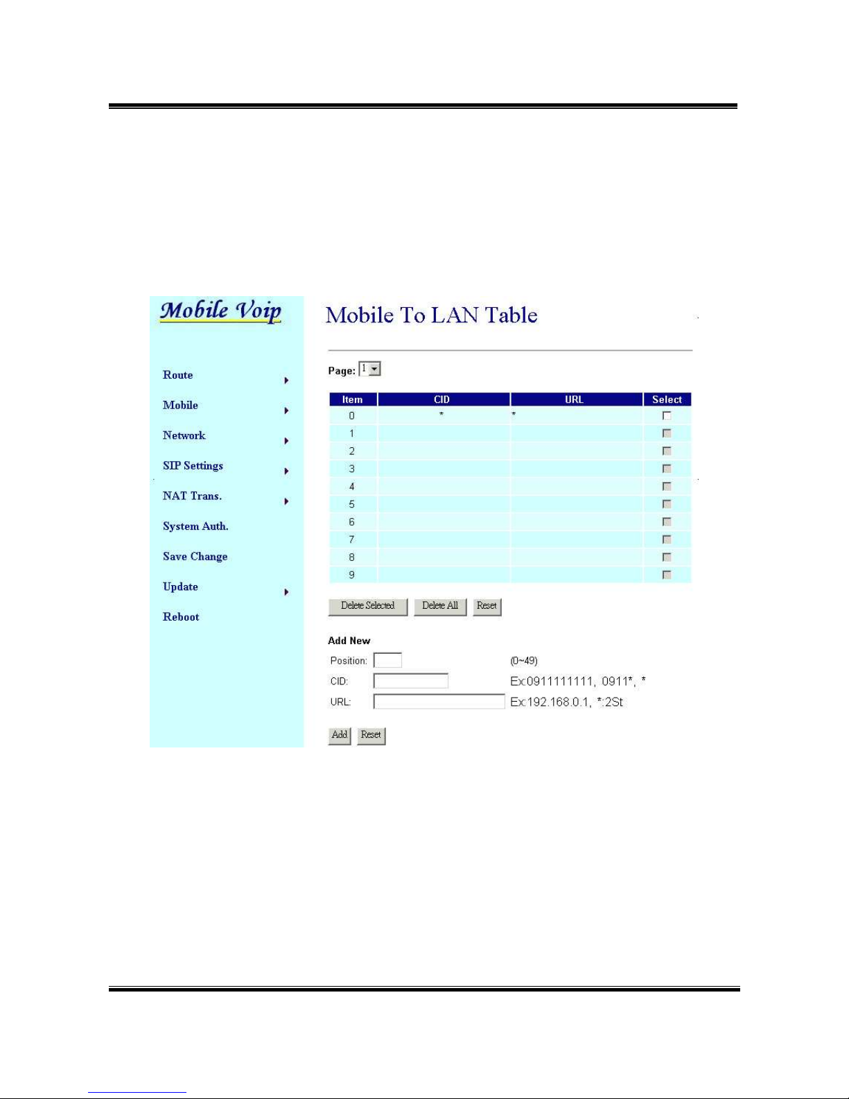
8.1.1 CID: caller ID, the numbers of incoming call
You could set the CID as the following formats:
(1) The complete number, e.g. 0911111111
(2) The prefix part plus *, e.g. 0911*. This format means any number
starting with 0911 will be accepted to transfer.
(3) *, this means any incoming call is accepted to transfer.
(4) N, this means the incoming call without showing its CID is accepted
to transfer.
Please note the priority of the routing rules; the CID with more digits
gets the priority.
8.1.2 URL:The IP address of destination
You could set the URL as the following formats:
(1) The complete IP address, e.g. 192.168.0.101
(2) The proxy extension numbers
(3) The phone numbers.
Note: If the device has registered at proxy server/Asterisk, you
can enter any destination phone number. Also note that
in the proxy server/Asterisk, you need to set the route of
destination phone number.
(4) Leave it blank or ‘N’, this mean to refuse to transfer.
(5) *, this means to transfer via 2-stage-dialing. The call will be
answered with a prompt dial tone for the caller to press the IP
address, proxy extension, or any phone number as destination.
The caller press the IP address on the phone keys: 192*168*0*101#
as 192.168.0.101
8.1.3 Example of Mobile to Lan setting:

-8-
(1) Mobile to Lan: 0932*, 0911123456
When the GSM numbers of the device is called, if the caller’s prefix
numbers are 0932, MV-370 transfers the call to 0911123456, then
0911123456 rings (while available).
Precondition:
a. MV-370 has registered at proxy server/Asterisk
b. The proxy server/Asterisk has the route of “09”
(2) Mobile to Lan: *, *
Any incoming call gets a prompt dial tone; so the caller can enter
any IP address, sip extension, or phone number.
Precondition:
a. SIP extension or phone number needs to register at SIP Proxy
Server or Asterisk.
b. Phone number, SIP Proxy Server or Asterisk needs to set the
route of destination phone number.
8.2 Route/ Mobile to LAN Speed Dial Settings
When you set both Mobile to LAN Speed Dial Settings and Mobile to
LAN settings at the same time, Mobile to LAN Speed Dial Settings
gets higher priority. Mobile to Lan setting will be not available.

-9-
The call is answered with a prompt dial tone for the caller to press the
“Num”, and then the device connects the “URL” as destination.
Example: after you call the GSM number of the device and hear a dial
tone, you press 0, then the lan phone of IP address:
192.168.0.107 rings.

-10-
8.3 Route/ LAN to Mobile Settings
In this page: Lan To Mobile able, you could set the routing rules to
transfer the calls incoming from Lan to Mobile. Maximum 50 sets.
When the Lan of the MV-370 is called, this device transfers the call to
Call Num according to the URL of the incoming call.
8.3.1 URL: The IP address or proxy extension numbers of the incoming
call.
You could set the URL as the following formats:
(1) The complete IP address, e.g. 192.168.0.101
(2) The proxy extension numbers, e.g. 103
(3) Part of an IP address plus *, e.g. 192.168.0.*. This means the IP
address starting with 192.168.0 would be accepted to transfer,
(4)
Part of the proxy extension numbers plus, e.g. 10*. This means the

-11-
extension numbers starting with 10 would be accepted to transfer.
8.3.2 Call Num: the phone numbers of destination.
You could set the Call Num as the following formats:
(1) The complete number, e.g. 0911111111
(2)
*
, this means to transfer via 2-stage-dialing. The call will be
answered with a prompt dial tone for the caller to press the destination
phone numbers, e.g. 0911111111
(3)
#
, this allow the caller with lan phone dial directly the destination
numbers.
Precondition:
(1) MV-370 and incoming lan Phone are both registered at proxy
server or Asterisk.
(2) Proxy server/asterisk has set the routing rules to assign
specific prefix of numbers to be transferred from MV-370.
(3) Lan to Mobile routing sets: *, #
Usage: You could dial on your lan phone call any destination
number with prefix of “09”. When your lan phone and
MV-370 had registered and “09” prefix is setted the routing
rules at proxy server or Asterisk.
(4)
#
['d'n]['a'ppp], this means to do the above routing, and to modify
the numbers.
Note: 'd'n means to delete the number of prefix,
'a'ppp means to add 'ppp' prefix.
E.g. #d2a09 means to call the registered numbers via
one-stage-dialing. The numbers are modified to: delete 2 digits of
prefix of the original numbers, then add 09 to be new prefix of the
destination numbers.

-12-
9. Mobile
9.1 Mobile/ Mobile Status
In this page: Mobile Status, you could get the information of your GSM
network and the latest operation.
(1) Network Registration: name of telecom carrier, which the SIM card of
this device registers at.
(2) SIM Card ID: SIM card ID.
(3) Signal Quality: place the antenna for higher signal, above 17 is better.
(4) Incoming IP: IP address of the last incoming call from Lan.
(5) Incoming IP Name: proxy extension name of incoming call from Lan.
(6) Outgoing IP: The IP address of the last outgoing call from Lan.
(7) Incoming Mob: The caller ID of the last incoming call from Mobile.
(8) Outgoing Mob: The destination numbers of the last outgoing call from
Mobile.

-13-
9.2 Mobile/ Mobile Setting
In this page: Mobile setting, you could adjust the parameter and click on
the option to fit your need. You could leave those default value before
you had tried the complete operation of this device.
(1) VoIP Volume: the sound volume that VoIP passes to Mobile.
(2) VoIP Gain: the sound volume that VoIP receives from Mobile.
(3) LAN DTMF Gain: the DTMF volume that Lan receives.
(4) Mobile In Gain: the DTMF volume that Mobile receives.
Note: you could adjust VoIP Volume and LAN DTMF Gain to fix the
DTMF problem in Lan to Mobile operation; you could adjust
VoIP Gain and Mobile In Gain to fix the DTMF problem in
Mobile to Lan operation.

-14-
(5) Caller ID: in Mobile to Lan operation, you could select “Clid” to
display the incoming call numbers, or “Fix” to display fixed SIP user
name on the destination phone.
(6) Presentation CLIR: In Lan to Mobile operation, you select
“Suppression” to hide the GSM numbers of the device, or
“Invocation” to display it on the destination phone.
(7) Mobile PIN Code: If you need to unlock pin code via MV-370, you can
click “On” and enter pin code.
(8)LAN Answer Mode:
This is the LAN answer time while in Lan to Mobile routing.
Answered: when mobile side answers, then connects the call
Alerted: when mobile side rings, then connects the call
Income: when lan side dials out, then connects the call soon
(9) and Type: if your device is Quad band model, you need to choose
your GSM frequency.

-15-
10. Network
In Network, you could check the Network status; configure the WLAN
Settings, LAN Settings and SNTP settings.
10.1 Network/ Status/ Network Status: information of current Network in
this page.

-16-
10.2 Network/ Network Settings/ Lan Settings: You can check the
current Network setting in this page.
The default IP is 192.168.0.100; you could change it to any available IP
address, or select different IP type to suit your environment.
(1) LAN Mode: select NAT
(2) Fixed IP: the TCP/IP Configuration item is to setup the WAN port’s
network environment. You may refer to your current network
environment to configure the system properly.
(3) DHCP client: you could refer to your current network environment to
configure the system properly
(4) PPPoE: If you have the PPPoE account from your Service Provider,
please input the Username and the Password correctly.
(5) After you input or modify the value, click the Submit button.

-17-
10.3 Network/ SNTP Settings:
You could select “On” to give SNTP function to this device.
Input the primary and secondary IP Address of SNTP Server to get the
date/time information. Also you could set the Time Zone according to
your location; and set the time to synchronize. After setting, remember to
click the Submit button.

-18-
11. SIP Setting
If you need, you could setup the Service Domain, Port Settings, Codec
Settings, RTP setting, RPort Setting and Other Settings.
If ISP provides the VoIP service, you need to input the related
information correctly to register at SIP Proxy Server.
11.1 SIP Setting/ Service Domain:
In this page, you should input the data refer to your ISP. Maximum is 3
accounts (Realm 1 to 3). You could dial out via first SIP account, and
receive via the three SIP accounts.
(1) Active: click “On” to enable the function in Service Domain, then input
the following items.
(2) Display name: input the name you would like to display.
(3) User name: input your user name in ISP.
(4) Register Name: input your register name in ISP.
(5) Register Password: input your password in ISP.
Other manuals for MV-370
5
Table of contents