Pro Antennas DMV-II User manual

DMV-II
80m
V Antenna
Pro Antennas ©2019
Assembly Instructions
0
DMV-II
Assembly Instructions
1
Thank you for purchasing this unique antenna product. We
hope that it will provide you with many hours of operation
and pleasure for years to come.!
Take a little time to carefully follow the instructions and study
the pictures to help understand the correct positioning and
alignment of the components.!
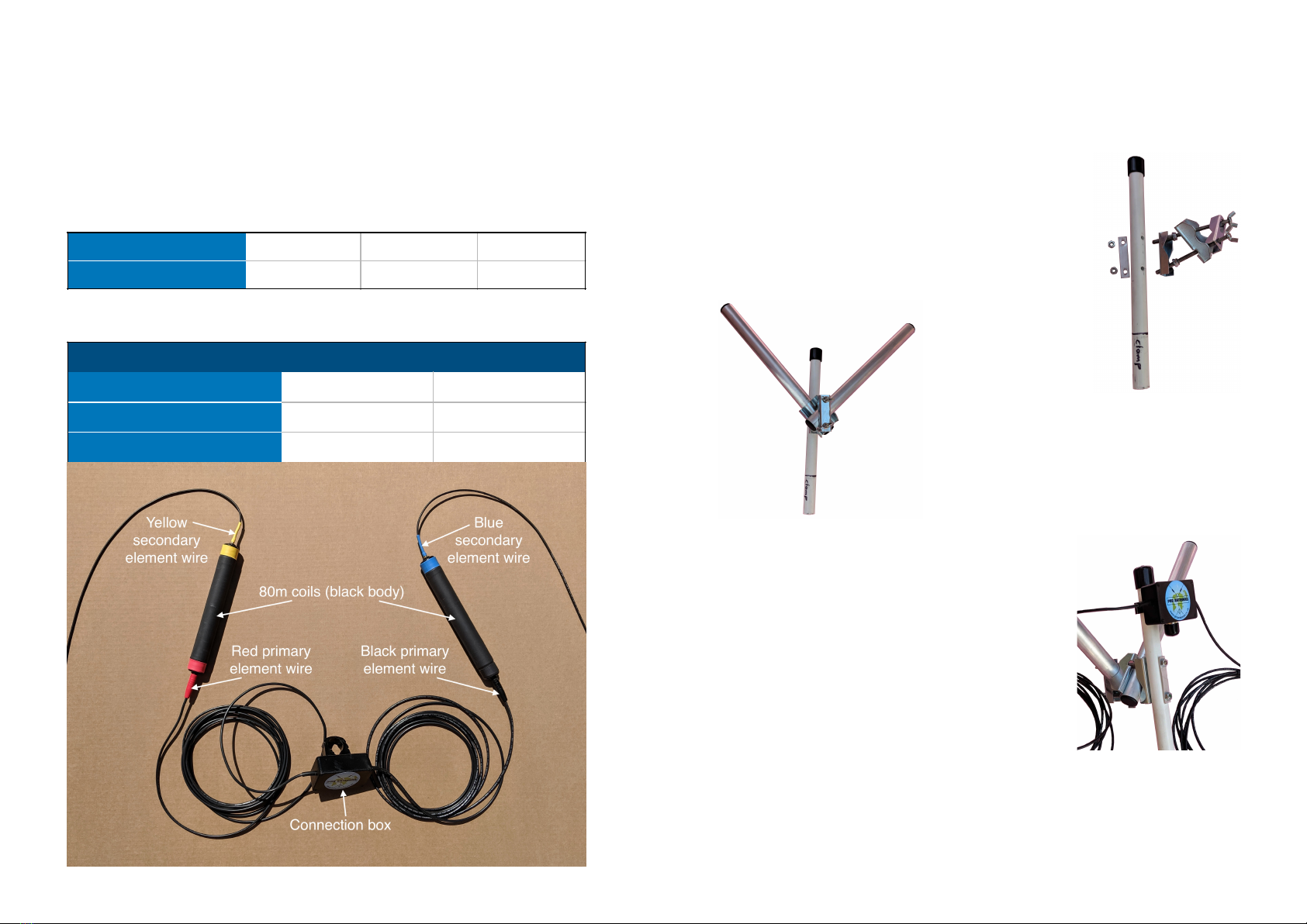
Components
Support assembly
1 x Glass reinforced plastic (GRP) rod (330mm)!
2 x Aluminium tubes (300mm) with end plugs!
1 x Large 8 nut clamp!
1 x Mast-boom clamp assembly!
Antenna elements
1 x Coax connection box & attached primary element wires!
2 x Telescopic poles!
2 x Black 80m Loading coils!
2 x Short bungee cords with ball toggles!
2 x Large twist cable clips!
2 x Medium twist cable clips!
2 x Secondary element wires!
8 x Secondary element wire extensions!
Options (if purchased)
2 x Blue 60m / Yellow 40m Loading coils!
Tools required
10mm and 13mm spanners
Initial Assembly
Caution: Always wear protective gloves when handling the
GRP rod to prevent skin irritation.
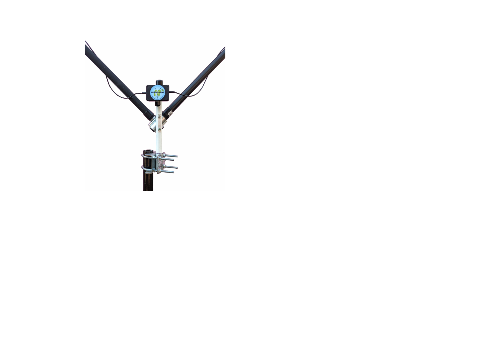
i. Attach the mast-boom clamp assembly
to the GRP rod by passing the studs
through the holes, placing the aluminium
strip over the studs and securing with the
M6 nuts.
ii. Position the 2 aluminium tubes in the
mast to boom clamp and secure by
tightening the wing nuts so that the
aluminium tubes form a V with the
clamped ends at the bottom.
iii. Remove the protective cover from the
top of the GRP rod and slide the coax
connection box clip onto the tube.
Ensure the Pro Antennas label is the right
way up and that the box is on the
opposite side of the GRP rod to the
mast-boom clamp assembly. Replace
the protective cover on the top of the
GRP rod.
Note: The support assembly from steps i - iii does not need
to be taken apart to use the antenna in another location. It
can be transported as a complete unit.
3
2
Colour coding
Band
80m
60m
40m
Body Colour
Black
Blue
Yellow
Loading coils
Element A
Element B
Primary wire
Red
Black
Secondary wire
Yellow
Blue
Extensions
White
White
Connections
Please note the secondary elements are asymmetric and
colour coding is used to ensure the correct connection of all
the elements.
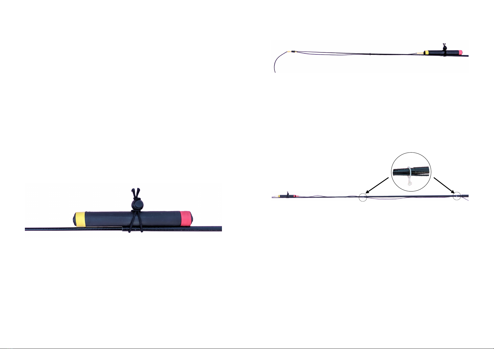
Assembly
2. Attach the correctly colour coded (yellow pictured or blue
for the other side) secondary element wire to the smallest
telescopic pole section by sliding the grommet to the
midpoint of the smallest section and sliding the small tube
over the end of the section. The remaining secondary
element wire will hang from the end of the pole. The
secondary element wire can now be plugged into the
matching coloured end of the loading coil. Ensure that the
wire is not so tight that any movement pulls on the plug.
1. Remove the top bung of the first telescopic pole and fully
extend the smallest section. Lock it in position with the
second section using a gentle pull and twist!
Caution: The smaller sections of the telescopic poles are
fragile and may break if bent too far.!
Slide out the second telescopic pole section and attach a
loading coil by wrapping a short bungee cord around the
centre of the coil and the smaller end of the second section
before looping the end of the cord around the ball toggle.
Tighten with the ball !
toggle as necessary.!
If your mast can be lowered to allow work at ground level, the
support assembly can now be attached to the mast by
clamping the large 8 nut clamp to the mast and tightening the
back plates to hold the bottom of the GRP rod. Otherwise,
the antenna elements will need to be set up first and the
complete installation clamped to the mast in situ.
4
3. Plug the main element wire (from the connection box) into
the matching coloured (red or black) end of the loading coil
and extend the third and fourth telescopic pole sections
using the supplied clips to hold the primary element wire
against the pole. The clips should be located at the larger
ends of sections 2 & 3 respectively, and the ends twisted
together to lock. Note: The plugs will pull out under tension
to avoid damage. The primary element wire should not be so !
tight that any movement !
pulls on the plug.!
4. Repeat steps 1 - 3 for the second telescopic pole.
5
5. Unscrew the telescopic pole end caps and remove the
polystyrene bead. Take care to ensure the smaller poles do
not slide out. Wrap a few turns of the primary element wire
around the pole and then slide the telescopic poles fully over
the aluminium poles of the support assembly. Fully extend
and lock the remaining sections.!
For a permanent installation, tape can be used to keep the
wire close to the poles. For temporary installations, this is not
necessary and some looseness of the wires will not affect
performance.
Set up
With no secondary element wire extensions attached, the
DMV-II is designed to be resonant at the top of the 80m band
(or 60m band with the option coils). This frequency is
dependent on the terrain and the height above ground. The
extension wires will move the resonance down into the
required part of the band.!
The secondary element wire extensions are provided in 2
each of 5, 10, 20 & 40cm lengths and may be cascaded to
give any length up to 75cm in 5cm increments. As a rule of
thumb, at 80m, adding 5cm to each side will decrease the
resonant frequency by around 20kHz. The sides can be
unbalanced by 5cm to give more resolution if necessary.!
Before first use, start with the 10cm extension wires and find
the resonant frequency using an antenna analyser or an SWR
meter and low power from your transmitter. Adjust the
lengths of the secondary wires until you have the best SWR
at the required frequency.!
Once you have found the appropriate lengths for the
frequency you want to use, it is worth noting this as a starting
point for subsequent setups.!
Note: the set up can be done at a lower height so that the
secondary wires can be adjusted from the ground but raising
the antenna will shift the resonant frequency up 10-20kHz
and this should be allowed for.
7
6
The DMV-II is a lightweight antenna with little wind loading
but normal precautions should be taken to secure the mast
to prevent it blowing over. The radiation pattern is generally
omni-directional and a rotator is not required.!
The antenna is designed to be resonant on the required
frequency and fine tuning of the centre frequency is achieved
by adding the secondary element wire extensions. The setup
is described in the next section.
6. The feeder coax can now be
attached to the connection box
and, if not already done, the
antenna assembly may be
clamped to the mast.!
9
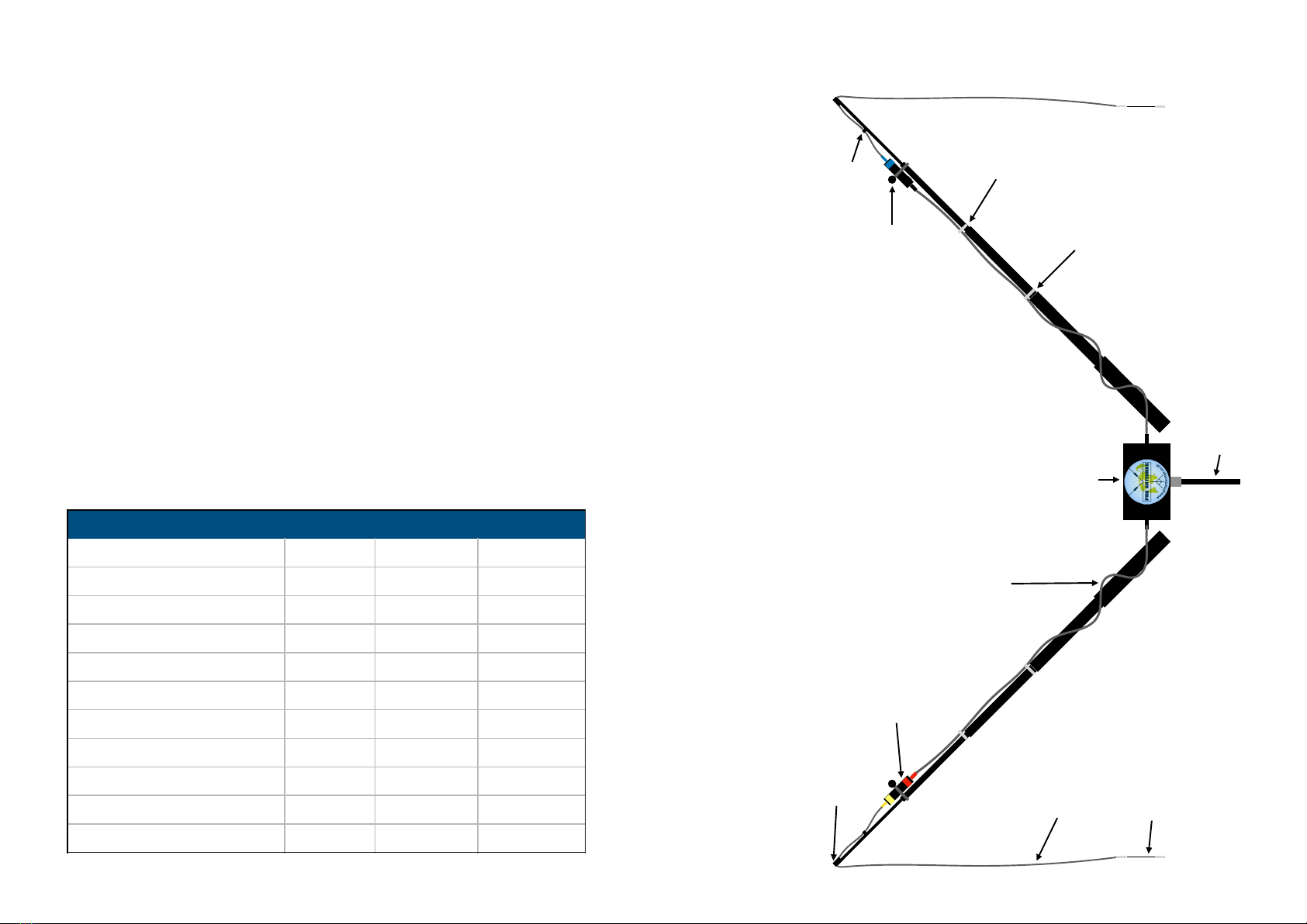
Configuration schematic
(Not to scale)
Large twist
cable clip
Medium twist
cable clip
Primary element wire
Secondary
element wire
Secondary element
wire extension
80m loading coil
Short bungee cord
with ball toggle
Grommet
Small tube
Connection box
Coax feeder
A
B
c 8.0m!
3kg!
32 - 50mm!
500W
8
QTH
Mhz
Ext A cm
Ext B cm
Extension length records
Specification
The DMV-II is a resonant V dipole with loading coils and
hanging secondary elements with fine tuning extensions.
Overall span of main elements!
Total weight including mast clamp!
Support mast diameter range!
Maximum peak envelope power
A mast height of 3 to 5m is ideal for DMV-II operation.
Use this table to record the required extension wire lengths
for your favourite frequency bands for quicker repeat setup.
Table of contents
Other Pro Antennas Antenna manuals


